oil AUDI A4 2000 B5 / 1.G AWM Engine Cylinder Head Remove And Install Workshop Manual
[x] Cancel search | Manufacturer: AUDI, Model Year: 2000, Model line: A4, Model: AUDI A4 2000 B5 / 1.GPages: 42, PDF Size: 0.87 MB
Page 1 of 42
15-1
Cylinder head, removing and
installing
Note:
Always replace the cylinder head bolts.
When performing repairs, replace seals,
gaskets, self-locking nuts and bolts which have
a specified tightening angle.
The hose connectors and hoses of charge air
system must be free of oil and grease before
assembling.
When installing an exchange cylinder head with
the camshafts installed, the contact surfaces
between bucket tappet and cam running
surface must be oiled after installation of the
cylinder head.
The plastic protectors fitted to protect the open
valves must only be removed immediately
before installing the cylinder head.
When installing a new cylinder head or cylinder
head gasket, drain off all the old coolant and re-
fill with new coolant.
Pa
ge 1 of 42 C
ylinder head, removin
g and installin
g
11/21/2002 htt
p://127.0.0.1:8080/audi/servlet/Dis
play?action=Goto&t
yp
e=re
pair&id=AUDI.B5.GE06.15.1
Page 4 of 42
15-3
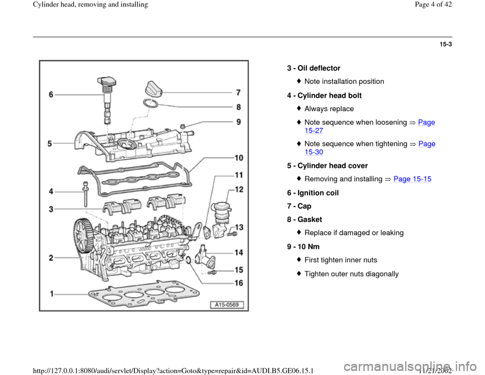
3 -
Oil deflector
Note installation position
4 -
Cylinder head bolt Always replaceNote sequence when loosening Page 15
-27
Note sequence when tightening Page 15
-30
5 -
Cylinder head cover
Removing and installing Page 15
-15
6 -
Ignition coil
7 -
Cap
8 -
Gasket
Replace if damaged or leaking
9 -
10 Nm First tighten inner nutsTighten outer nuts diagonally
Pa
ge 4 of 42 C
ylinder head, removin
g and installin
g
11/21/2002 htt
p://127.0.0.1:8080/audi/servlet/Dis
play?action=Goto&t
yp
e=re
pair&id=AUDI.B5.GE06.15.1
Page 13 of 42
15-12
- Disconnect coolant hoses from upper coolant
line.
- Move electrical wiring at top of coolant line
aside.
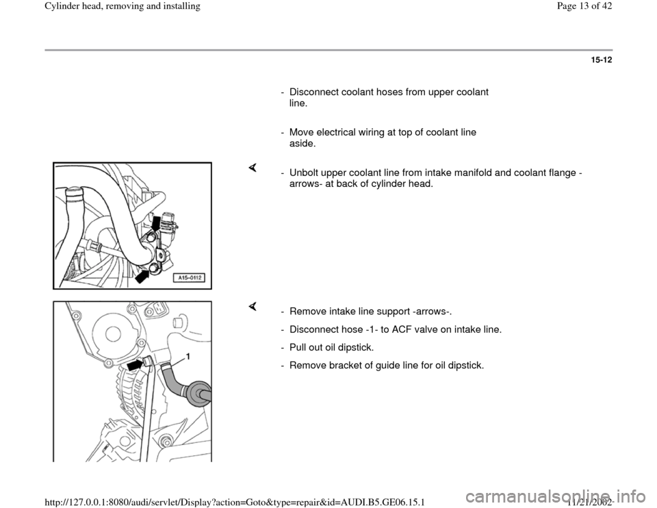
- Unbolt upper coolant line from intake manifold and coolant flange -
arrows- at back of cylinder head.
- Remove intake line support -arrows-.
- Disconnect hose -1- to ACF valve on intake line.
- Pull out oil dipstick.
- Remove bracket of guide line for oil dipstick.
Pa
ge 13 of 42 C
ylinder head, removin
g and installin
g
11/21/2002 htt
p://127.0.0.1:8080/audi/servlet/Dis
play?action=Goto&t
yp
e=re
pair&id=AUDI.B5.GE06.15.1
Page 14 of 42
15-13
- Remove suction hose from flange and
remove.
Note:
Plug intake ports on cylinder head with clean
cloths.
Installing
Installation is carried out in the reverse order of
removal; note the following:
Note:
All cable ties which are released or cut open
when removing must be located in the same
position when installing.
Hose connections and hoses of charge air
system must be free of oil and grease before
assembling.
Replace seals and gaskets.
- Top up coolant Page 19
-7 .
- After connecting battery, enter anti-theft code for
radio.
Pa
ge 14 of 42 C
ylinder head, removin
g and installin
g
11/21/2002 htt
p://127.0.0.1:8080/audi/servlet/Dis
play?action=Goto&t
yp
e=re
pair&id=AUDI.B5.GE06.15.1
Page 20 of 42
15-17
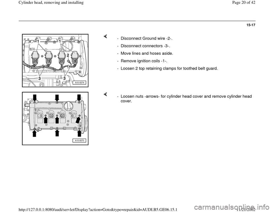
- Disconnect Ground wire -2-.
- Disconnect connectors -3-.
- Move lines and hoses aside.
- Remove ignition coils -1-.
- Loosen 2 top retaining clamps for toothed belt guard.
- Loosen nuts -arrows- for cylinder head cover and remove cylinder head
cover.
Pa
ge 20 of 42 C
ylinder head, removin
g and installin
g
11/21/2002 htt
p://127.0.0.1:8080/audi/servlet/Dis
play?action=Goto&t
yp
e=re
pair&id=AUDI.B5.GE06.15.1
Page 26 of 42
15-23
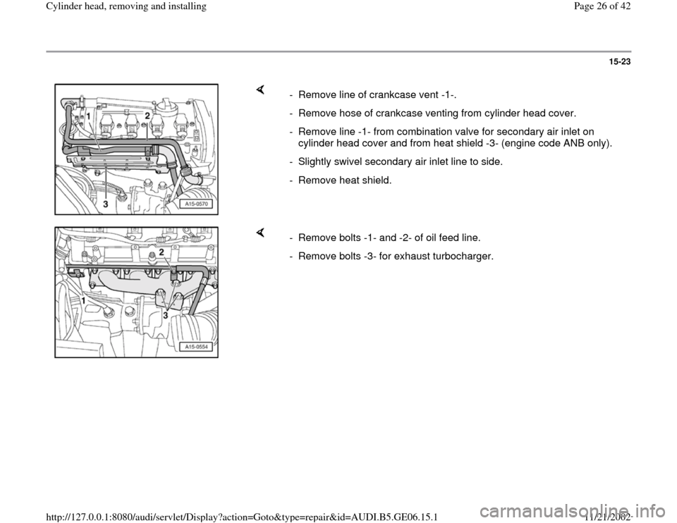
- Remove line of crankcase vent -1-.
- Remove hose of crankcase venting from cylinder head cover.
- Remove line -1- from combination valve for secondary air inlet on
cylinder head cover and from heat shield -3- (engine code ANB only).
- Slightly swivel secondary air inlet line to side.
- Remove heat shield.
- Remove bolts -1- and -2- of oil feed line.
- Remove bolts -3- for exhaust turbocharger.
Pa
ge 26 of 42 C
ylinder head, removin
g and installin
g
11/21/2002 htt
p://127.0.0.1:8080/audi/servlet/Dis
play?action=Goto&t
yp
e=re
pair&id=AUDI.B5.GE06.15.1
Page 27 of 42
15-24
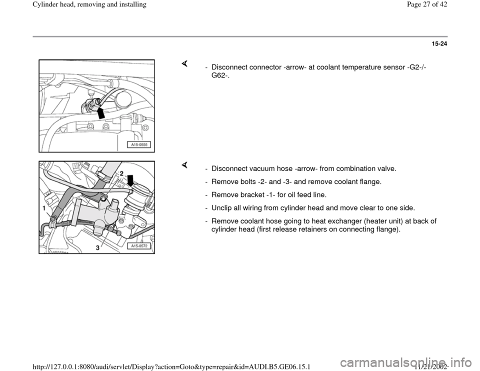
- Disconnect connector -arrow- at coolant temperature sensor -G2-/-
G62-.
- Disconnect vacuum hose -arrow- from combination valve.
- Remove bolts -2- and -3- and remove coolant flange.
- Remove bracket -1- for oil feed line.
- Unclip all wiring from cylinder head and move clear to one side.
- Remove coolant hose going to heat exchanger (heater unit) at back of
cylinder head (first release retainers on connecting flange).
Pa
ge 27 of 42 C
ylinder head, removin
g and installin
g
11/21/2002 htt
p://127.0.0.1:8080/audi/servlet/Dis
play?action=Goto&t
yp
e=re
pair&id=AUDI.B5.GE06.15.1
Page 29 of 42
15-26
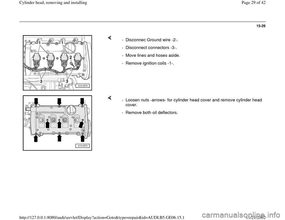
- Disconnec Ground wire -2-.
- Disconnect connectors -3-.
- Move lines and hoses aside.
- Remove ignition coils -1-.
- Loosen nuts -arrows- for cylinder head cover and remove cylinder head
cover.
- Remove both oil deflectors.
Pa
ge 29 of 42 C
ylinder head, removin
g and installin
g
11/21/2002 htt
p://127.0.0.1:8080/audi/servlet/Dis
play?action=Goto&t
yp
e=re
pair&id=AUDI.B5.GE06.15.1
Page 32 of 42
the silicone layer or the indented area will lead
to leaks.
No oil or coolant must be allowed to remain in
the blind holes for the cylinder head bolts in the
cylinder head.
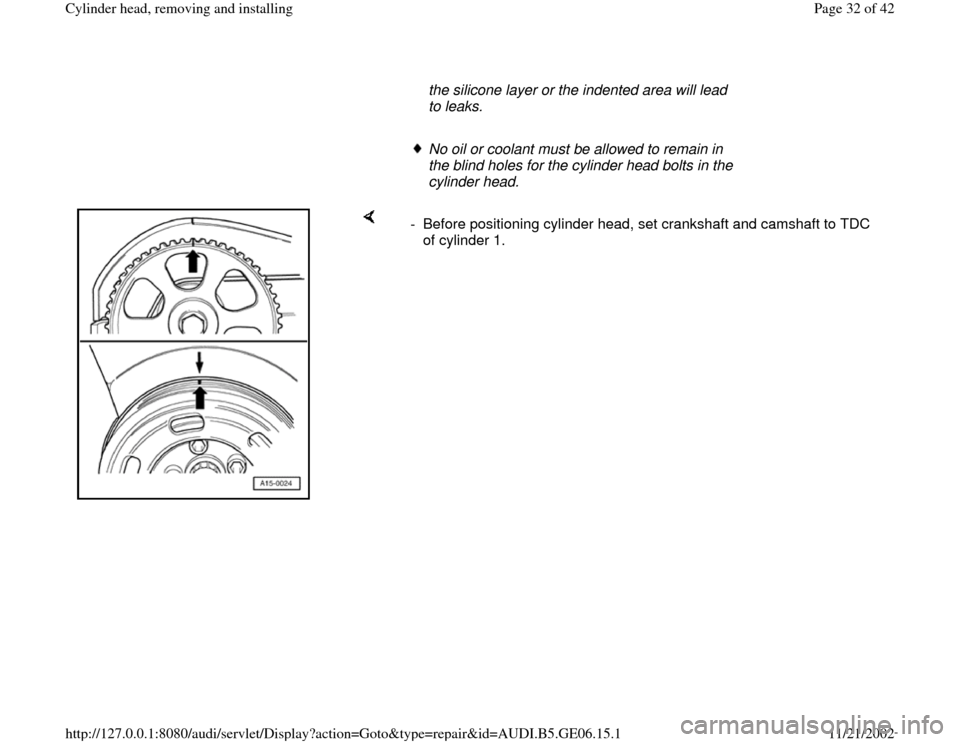
- Before positioning cylinder head, set crankshaft and camshaft to TDC
of cylinder 1.
Pa
ge 32 of 42 C
ylinder head, removin
g and installin
g
11/21/2002 htt
p://127.0.0.1:8080/audi/servlet/Dis
play?action=Goto&t
yp
e=re
pair&id=AUDI.B5.GE06.15.1
Page 39 of 42
15-34
Test conditions:
Engine oil temperature at least 30 C
Battery voltage at least 12.7 V
Test sequence
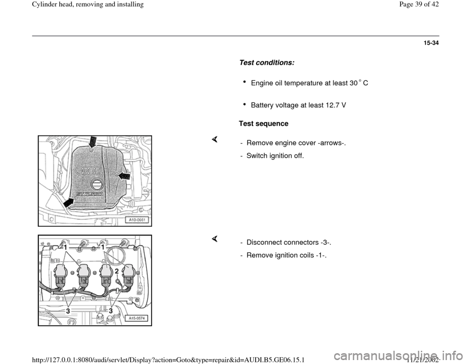
- Remove engine cover -arrows-.
- Switch ignition off.
- Disconnect connectors -3-.
- Remove ignition coils -1-.
Pa
ge 39 of 42 C
ylinder head, removin
g and installin
g
11/21/2002 htt
p://127.0.0.1:8080/audi/servlet/Dis
play?action=Goto&t
yp
e=re
pair&id=AUDI.B5.GE06.15.1