wiring AUDI A4 2000 B5 / 1.G Brakes Can Bus Workshop Manual
[x] Cancel search | Manufacturer: AUDI, Model Year: 2000, Model line: A4, Model: AUDI A4 2000 B5 / 1.GPages: 12, PDF Size: 0.06 MB
Page 3 of 12
01-27
CAN-bus system, checking
The DTC table indicated you needed to check
the bus:
- Using the relevant wiring diagram, determine
how many control modules are connected to the
CAN-bus.
- Check that the multiple connectors of the control
modules are properly connected (unobstructed).
- Connect the VAG1551 (or VAG1552) scan tool
and press the -0- button twice to select the
"Automatic Check" function 00.
- Before checking the bus wires, make sure that
none of the control modules connected have a
function malfunction.
Note:
In this context, a function malfunction means a
malfunction that doesn't directly affect the bus
system, but that interrupts the functioning of a
system. This could be a malfunctioning sensor,
for example. A malfunctioning sensor would
mean that the sensor signal could no longer be
used for data transfer in the bus system. This
type of malfunction indirectly affects the bus
system. Communication to the control modules
Pa
ge 3 of 12 CAN-
bus
11/20/2002 htt
p://127.0.0.1:8080/audi/servlet/Dis
play?action=Goto&t
yp
e=re
pair&id=AUDI.B5.SU02.01.3
Page 7 of 12
01-29
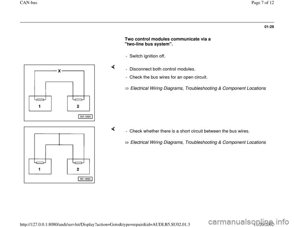
Two control modules communicate via a
"two-line bus system".
- Switch ignition off.
Electrical Wiring Diagrams, Troubleshooting & Component Locations - Disconnect both control modules.
- Check the bus wires for an open circuit.
Electrical Wiring Diagrams, Troubleshooting & Component Locations - Check whether there is a short circuit between the bus wires.
Pa
ge 7 of 12 CAN-
bus
11/20/2002 htt
p://127.0.0.1:8080/audi/servlet/Dis
play?action=Goto&t
yp
e=re
pair&id=AUDI.B5.SU02.01.3
Page 9 of 12
01-31
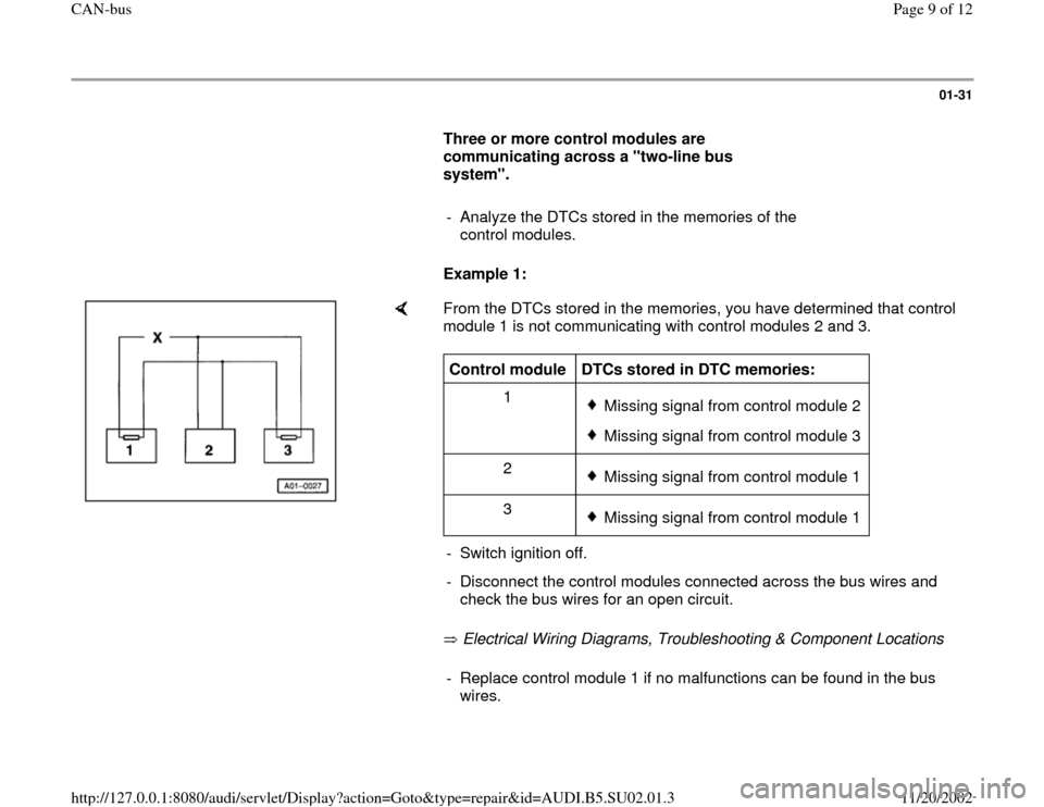
Three or more control modules are
communicating across a "two-line bus
system".
- Analyze the DTCs stored in the memories of the
control modules.
Example 1:
From the DTCs stored in the memories, you have determined that control
module 1 is not communicating with control modules 2 and 3.
Electrical Wiring Diagrams, Troubleshooting & Component Locations Control module
DTCs stored in DTC memories:
1
Missing signal from control module 2Missing signal from control module 3
2 Missing signal from control module 1
3 Missing signal from control module 1
- Switch ignition off.
- Disconnect the control modules connected across the bus wires and
check the bus wires for an open circuit. - Replace control module 1 if no malfunctions can be found in the bus
wires.
Pa
ge 9 of 12 CAN-
bus
11/20/2002 htt
p://127.0.0.1:8080/audi/servlet/Dis
play?action=Goto&t
yp
e=re
pair&id=AUDI.B5.SU02.01.3
Page 10 of 12
01-32
Example 2:
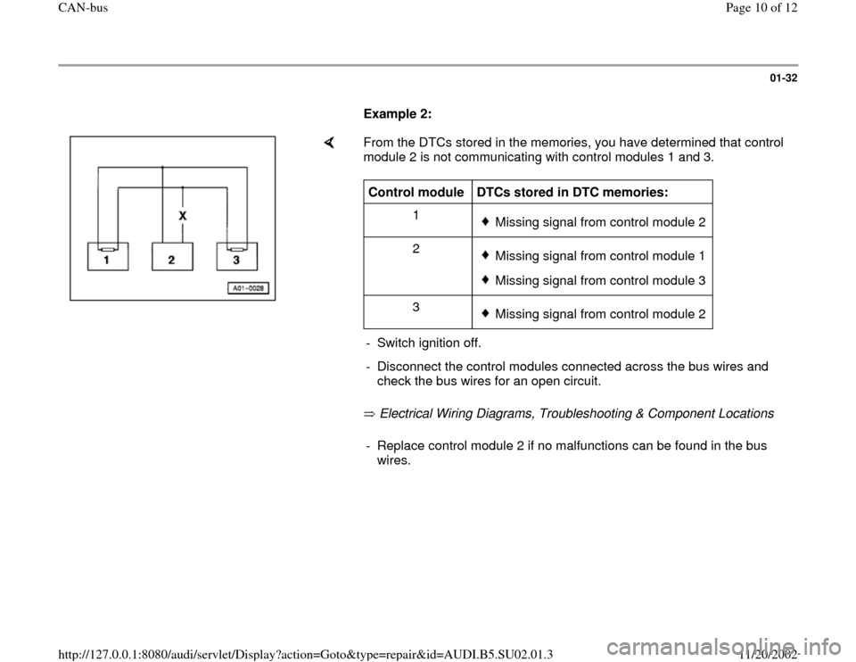
From the DTCs stored in the memories, you have determined that control
module 2 is not communicating with control modules 1 and 3.
Electrical Wiring Diagrams, Troubleshooting & Component Locations Control module
DTCs stored in DTC memories:
1
Missing signal from control module 2
2 Missing signal from control module 1Missing signal from control module 3
3 Missing signal from control module 2
- Switch ignition off.
- Disconnect the control modules connected across the bus wires and
check the bus wires for an open circuit. - Replace control module 2 if no malfunctions can be found in the bus
wires.
Pa
ge 10 of 12 CAN-
bus
11/20/2002 htt
p://127.0.0.1:8080/audi/servlet/Dis
play?action=Goto&t
yp
e=re
pair&id=AUDI.B5.SU02.01.3
Page 11 of 12
01-33
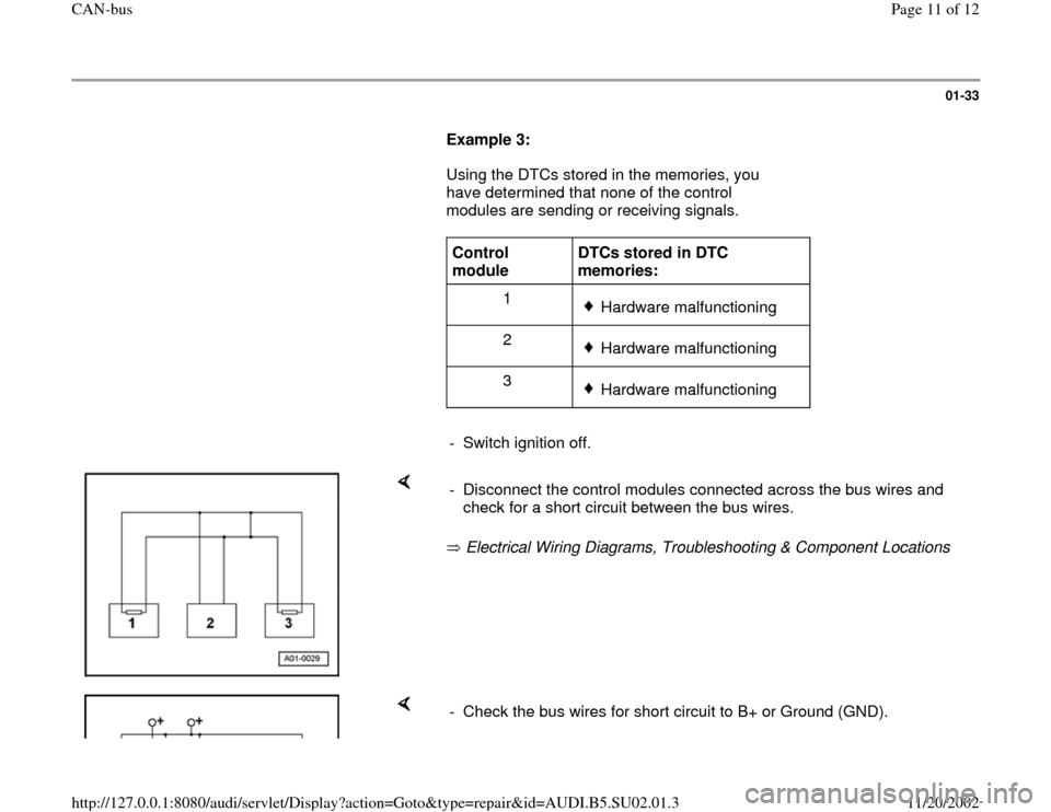
Example 3:
Using the DTCs stored in the memories, you
have determined that none of the control
modules are sending or receiving signals.
Control
module DTCs stored in DTC
memories:
1
Hardware malfunctioning
2 Hardware malfunctioning
3 Hardware malfunctioning
- Switch ignition off.
Electrical Wiring Diagrams, Troubleshooting & Component Locations - Disconnect the control modules connected across the bus wires and
check for a short circuit between the bus wires.
- Check the bus wires for short circuit to B+ or Ground (GND).
Pa
ge 11 of 12 CAN-
bus
11/20/2002 htt
p://127.0.0.1:8080/audi/servlet/Dis
play?action=Goto&t
yp
e=re
pair&id=AUDI.B5.SU02.01.3