lock AUDI A4 2001 B5 / 1.G Technical Features Design And Function
[x] Cancel search | Manufacturer: AUDI, Model Year: 2001, Model line: A4, Model: AUDI A4 2001 B5 / 1.GPages: 88, PDF Size: 10.42 MB
Page 45 of 88
Downloaded from www.Manualslib.com manuals search engine
45
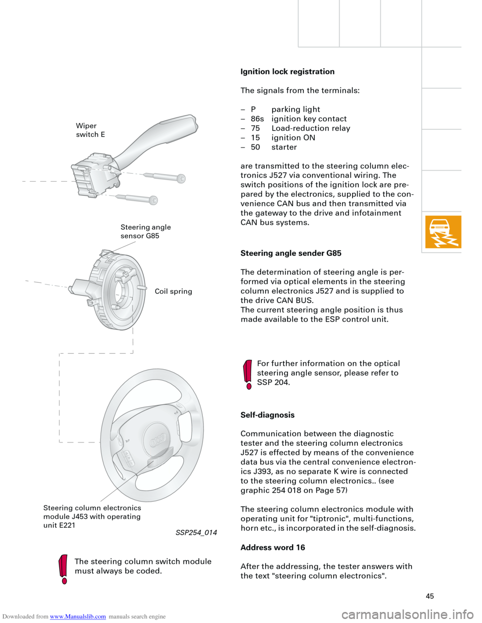
Steering angle sender G85
The determination of steering angle is per-
formed via optical elements in the steering
column electronics J527 and is supplied to
the drive CAN BUS.
The current steering angle position is thus
made available to the ESP control unit.
The steering column switch module
must always be coded.
For further information on the optical
steering angle sensor, please refer to
SSP 204.
Self-diagnosis
Communication between the diagnostic
tester and the steering column electronics
J527 is effected by means of the convenience
data bus via the central convenience electron-
ics J393, as no separate K wire is connected
to the steering column electronics.. (see
graphic 254 018 on Page 57)
The steering column electronics module with
operating unit for "tiptronic", multi-functions,
horn etc., is incorporated in the self-diagnosis.
Address word 16
After the addressing, the tester answers with
the text "steering column electronics".
Wiper
switch E
Steering angle
sensor G85
Steering column electronics
module J453 with operating
unit E221
Ignition lock registration
The signals from the terminals:
– P parking light
– 86s ignition key contact
– 75 Load-reduction relay
– 15 ignition ON
– 50 starter
are transmitted to the steering column elec-
tronics J527 via conventional wiring. The
switch positions of the ignition lock are pre-
pared by the electronics, supplied to the con-
venience CAN bus and then transmitted via
the gateway to the drive and infotainment
CAN bus systems.
Coil spring
RT
SSP254_014
Page 46 of 88
Downloaded from www.Manualslib.com manuals search engine
46
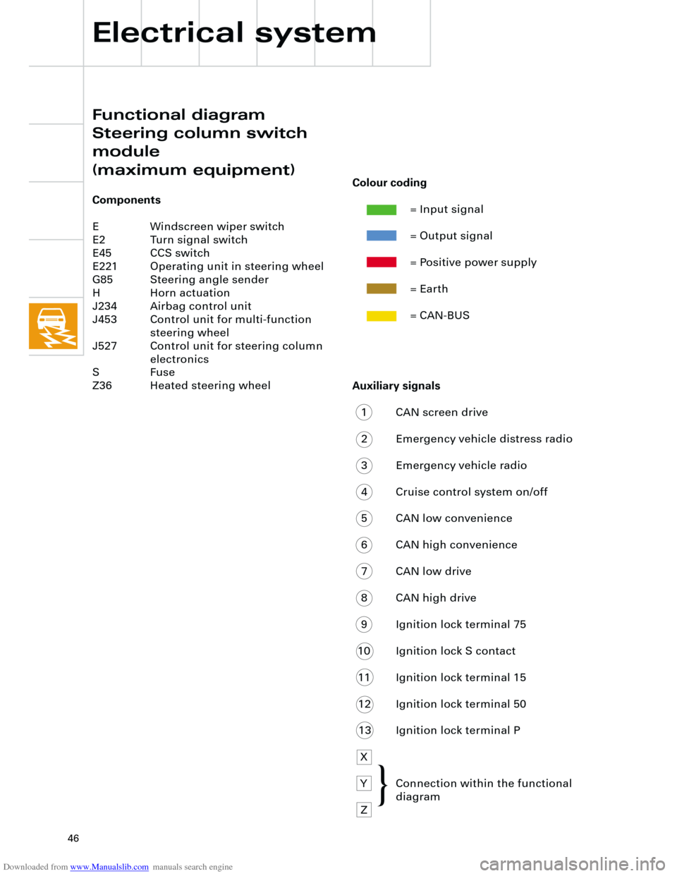
Auxiliary signals
1 CAN screen drive
2 Emergency vehicle distress radio
3 Emergency vehicle radio
4 Cruise control system on/off
5 CAN low convenience
6 CAN high convenience
7 CAN low drive
8 CAN high drive
9 Ignition lock terminal 75
10 Ignition lock S contact
11 Ignition lock terminal 15
12 Ignition lock terminal 50
13 Ignition lock terminal P
X
Y Connection within the functional
diagram
Z
Electrical system
Functional diagram
Steering column switch
module
(maximum equipment)
Components
E Windscreen wiper switch
E2 Turn signal switch
E45 CCS switch
E221 Operating unit in steering wheel
G85 Steering angle sender
H Horn actuation
J234 Airbag control unit
J453 Control unit for multi-function
steering wheel
J527 Control unit for steering column
electronics
S Fuse
Z36 Heated steering wheel
Colour coding
= Input signal
= Output signal
= Positive power supply
= Earth
= CAN-BUS
{
Page 54 of 88
Downloaded from www.Manualslib.com manuals search engine
54
5 V/Div.=10 ms/Div.
0 T
Electrical system
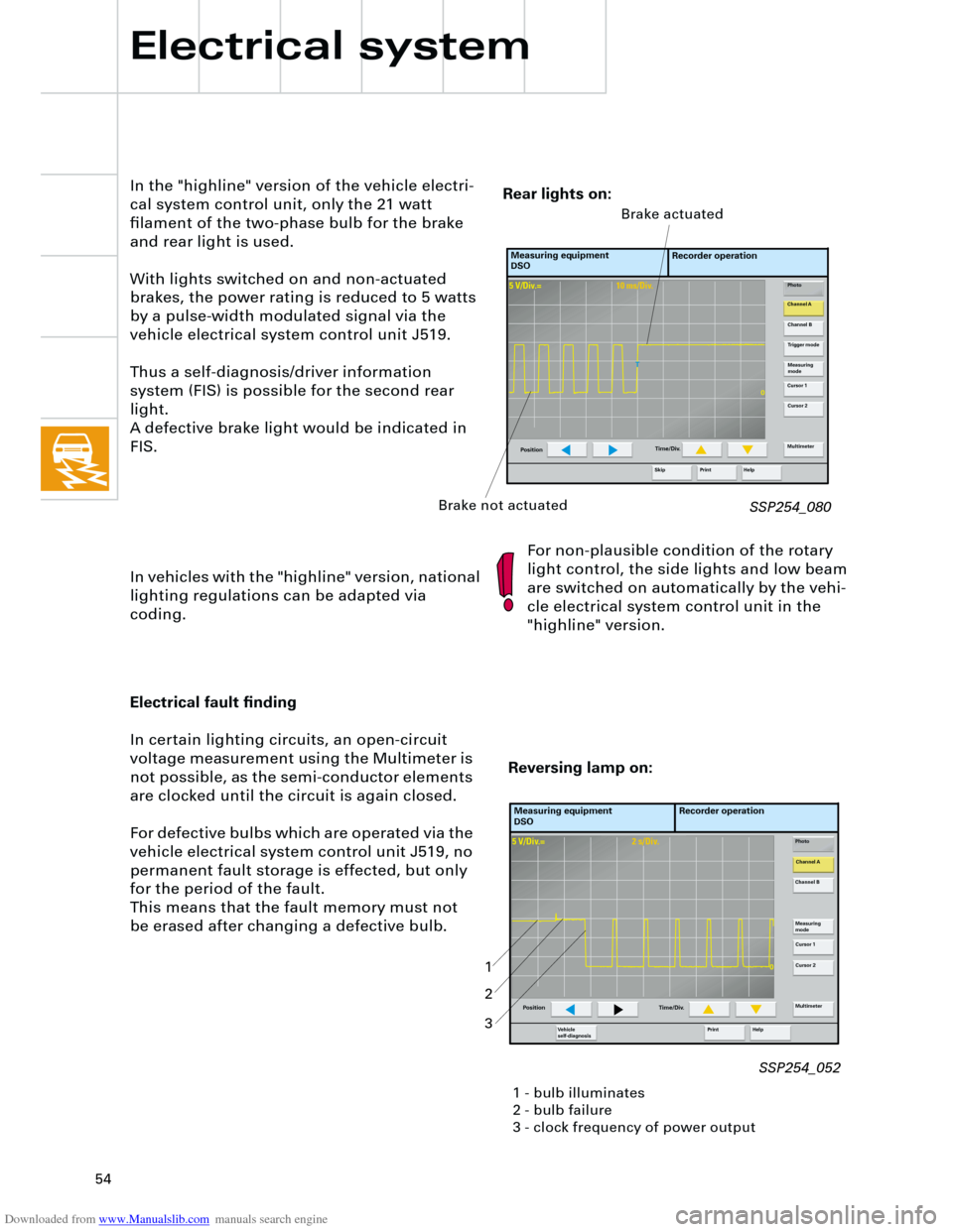
In the "highline" version of the vehicle electri-
cal system control unit, only the 21 watt
filament of the two-phase bulb for the brake
and rear light is used.
With lights switched on and non-actuated
brakes, the power rating is reduced to 5 watts
by a pulse-width modulated signal via the
vehicle electrical system control unit J519.
Thus a self-diagnosis/driver information
system (FIS) is possible for the second rear
light.
A defective brake light would be indicated in
FIS.
In vehicles with the "highline" version, national
lighting regulations can be adapted via
coding.For non-plausible condition of the rotary
light control, the side lights and low beam
are switched on automatically by the vehi-
cle electrical system control unit in the
"highline" version.
SSP254_080
Measuring equipment
DSORecorder operation
Photo
Channel A
Channel B
Measuring
mode
Cursor 1
Cursor 2
Multimeter
Help Print
PositionTime/Div.
Trigger mode
Skip
Brake not actuatedBrake actuated
Rear lights on:
5 V/Div.=2 s/Div.
0
Electrical fault finding
In certain lighting circuits, an open-circuit
voltage measurement using the Multimeter is
not possible, as the semi-conductor elements
are clocked until the circuit is again closed.
For defective bulbs which are operated via the
vehicle electrical system control unit J519, no
permanent fault storage is effected, but only
for the period of the fault.
This means that the fault memory must not
be erased after changing a defective bulb.
Measuring equipment
DSORecorder operation
Photo
Channel A
Channel B
Measuring
mode
Cursor 1
Cursor 2
Multimeter
Help Print Ve h i c l e
self-diagnosis
Position Time/Div.
Reversing lamp on:
1 - bulb illuminates
2 - bulb failure
3 - clock frequency of power output
1
2
3
SSP254_052
Page 55 of 88
Downloaded from www.Manualslib.com manuals search engine
55
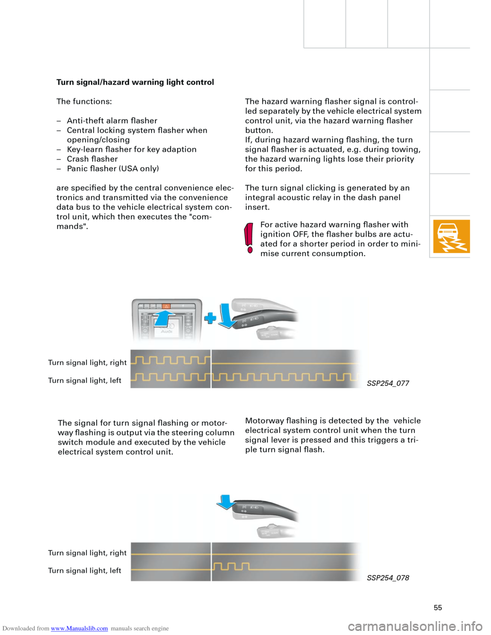
The hazard warning flasher signal is control-
led separately by the vehicle electrical system
control unit, via the hazard warning flasher
button.
If, during hazard warning flashing, the turn
signal flasher is actuated, e.g. during towing,
the hazard warning lights lose their priority
for this period.
The turn signal clicking is generated by an
integral acoustic relay in the dash panel
insert.
Turn signal/hazard warning light control
The functions:
– Anti-theft alarm flasher
– Central locking system flasher when
opening/closing
– Key-learn flasher for key adaption
– Crash flasher
– Panic flasher (USA only)
are specified by the central convenience elec-
tronics and transmitted via the convenience
data bus to the vehicle electrical system con-
trol unit, which then executes the "com-
mands".
The signal for turn signal flashing or motor-
way flashing is output via the steering column
switch module and executed by the vehicle
electrical system control unit.
For active hazard warning flasher with
ignition OFF, the flasher bulbs are actu-
ated for a shorter period in order to mini-
mise current consumption.
Motorway flashing is detected by the vehicle
electrical system control unit when the turn
signal lever is pressed and this triggers a tri-
ple turn signal flash.
Turn signal light, right
Turn signal light, left
Turn signal light, right
Turn signal light, left
SSP254_077
SSP254_078
Page 57 of 88
Downloaded from www.Manualslib.com manuals search engine
57
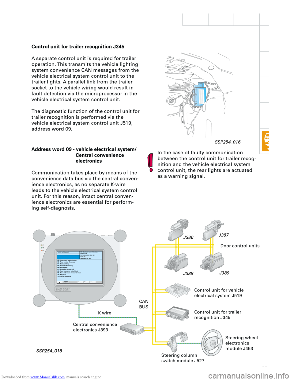
Control unit for trailer recognition J345
A separate control unit is required for trailer
operation. This transmits the vehicle lighting
system convenience CAN messages from the
vehicle electrical system control unit to the
trailer lights. A parallel link from the trailer
socket to the vehicle wiring would result in
fault detection via the microprocessor in the
vehicle electrical system control unit.
The diagnostic function of the control unit for
trailer recognition is performed via the
vehicle electrical system control unit J519,
address word 09.
In the case of faulty communication
between the control unit for trailer recog-
nition and the vehicle electrical system
control unit, the rear lights are actuated
as a warning signal.
RT
Address word 09 - vehicle electrical system/
Central convenience
electronics
Communication takes place by means of the
convenience data bus via the central conven-
ience electronics, as no separate K-wire
leads to the vehicle electrical system control
unit. For this reason, intact central conven-
ience electronics are essential for perform-
ing self-diagnosis.
K wireCAN
BUS
Central convenience
electronics J393
SSP254_018J389
J388J387
J386
Door control units
Control unit for vehicle
electrical system J519
Control unit for trailer
recognition J345
09 – Electronic central electrics
8E0907279B
int. load module RDW 0811
Code 101
Dealership No. 6803
02 - Interrogate fault memory
03 - Final control diagnosis
04 - Basic setting
05 - Erase fault memory
06 - End output
07 - Encoding control unit
08 - Read measured value block
09 - Read individual measured value
10 - Adaption
11 - Log-in procedure
Measuring
equipmentSkip PrintHelp
Steering column
switch module J527
Vehicle self-diagnosis
Steering wheel
electronics
module J453
SSP254_016
VAS 5051
Page 58 of 88
Downloaded from www.Manualslib.com manuals search engine
58
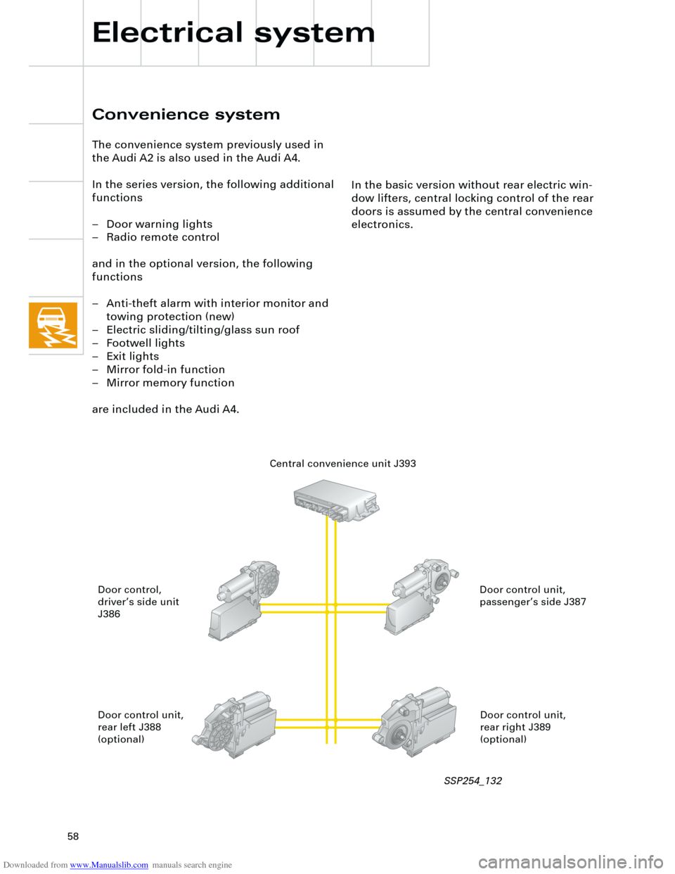
In the basic version without rear electric win-
dow lifters, central locking control of the rear
doors is assumed by the central convenience
electronics.
Convenience system
The convenience system previously used in
the Audi A2 is also used in the Audi A4.
In the series version, the following additional
functions
– Door warning lights
– Radio remote control
and in the optional version, the following
functions
– Anti-theft alarm with interior monitor and
towing protection (new)
– Electric sliding/tilting/glass sun roof
– Footwell lights
– Exit lights
– Mirror fold-in function
– Mirror memory function
are included in the Audi A4.
Electrical system
Central convenience unit J393
Door control unit,
passenger’s side J387 Door control,
driver’s side unit
J386
Door control unit,
rear right J389
(optional) Door control unit,
rear left J388
(optional)
SSP254_132
Page 59 of 88
Downloaded from www.Manualslib.com manuals search engine
59
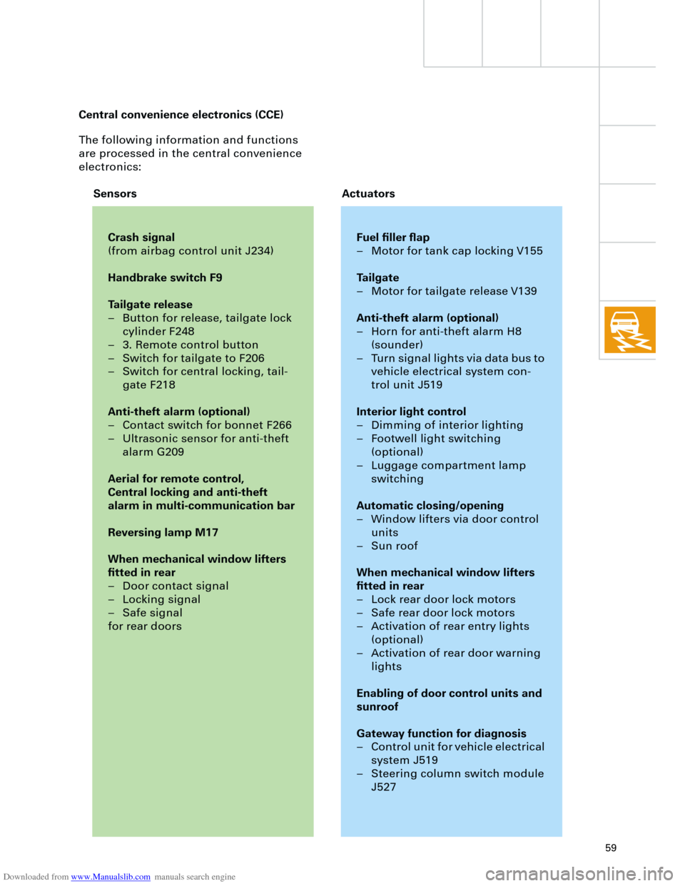
The following information and functions
are processed in the central convenience
electronics:
Crash signal
(from airbag control unit J234)
Handbrake switch F9
Tailgate release
– Button for release, tailgate lock
cylinder F248
– 3. Remote control button
– Switch for tailgate to F206
– Switch for central locking, tail-
gate F218
Anti-theft alarm (optional)
– Contact switch for bonnet F266
– Ultrasonic sensor for anti-theft
alarm G209
Aerial for remote control,
Central locking and anti-theft
alarm in multi-communication bar
Reversing lamp M17
When mechanical window lifters
fitted in rear
– Door contact signal
– Locking signal
– Safe signal
for rear doors
Fuel filler flap
– Motor for tank cap locking V155
Tailgate
– Motor for tailgate release V139
Anti-theft alarm (optional)
– Horn for anti-theft alarm H8
(sounder)
– Turn signal lights via data bus to
vehicle electrical system con-
trol unit J519
Interior light control
– Dimming of interior lighting
– Footwell light switching
(optional)
– Luggage compartment lamp
switching
Automatic closing/opening
– Window lifters via door control
units
– Sun roof
When mechanical window lifters
fitted in rear
– Lock rear door lock motors
– Safe rear door lock motors
– Activation of rear entry lights
(optional)
– Activation of rear door warning
lights
Enabling of door control units and
sunroof
Gateway function for diagnosis
– Control unit for vehicle electrical
system J519
– Steering column switch module
J527
Sensors Actuators Central convenience electronics (CCE)
Page 60 of 88
Downloaded from www.Manualslib.com manuals search engine
60
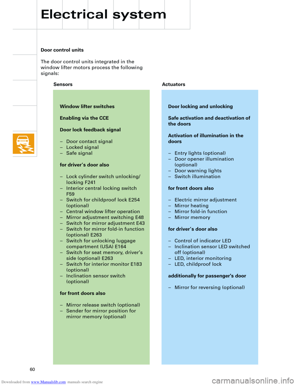
Door control units
The door control units integrated in the
window lifter motors process the following
signals:
Window lifter switches
Enabling via the CCE
Door lock feedback signal
– Door contact signal
– Locked signal
– Safe signal
for driver’s door also
– Lock cylinder switch unlocking/
locking F241
– Interior central locking switch
F59
– Switch for childproof lock E254
(optional)
– Central window lifter operation
– Mirror adjustment switching E48
– Switch for mirror adjustment E43
– Switch for mirror fold-in function
(optional) E263
– Switch for unlocking luggage
compartment (USA) E164
– Switch for seat memory, driver’s
side (optional) E263
– Switch for interior monitor E183
(optional)
– Inclination sensor switch
(optional)
for front doors also
– Mirror release switch (optional)
– Sender for mirror position for
mirror memory (optional)
Door locking and unlocking
Safe activation and deactivation of
the doors
Activation of illumination in the
doors
– Entry lights (optional)
– Door opener illumination
(optional)
– Door warning lights
– Switch illumination
for front doors also
– Electric mirror adjustment
– Mirror heating
– Mirror fold-in function
– Mirror memory
for driver’s door also
– Control of indicator LED
– Inclination sensor LED switched
off (optional)
– LED, interior monitoring
– LED, childproof lock
additionally for passenger's door
– Mirror for reversing (optional)
Sensors Actuators
Electrical system
Page 62 of 88
Downloaded from www.Manualslib.com manuals search engine
62
TS
Electrical system
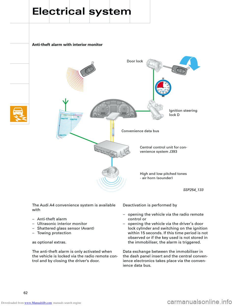
The Audi A4 convenience system is available
with
– Anti-theft alarm
– Ultrasonic interior monitor
– Shattered glass sensor (Avant)
– Towing protection
as optional extras.
The anti-theft alarm is only activated when
the vehicle is locked via the radio remote con-
trol and by closing the driver's door.Deactivation is performed by
– opening the vehicle via the radio remote
control or
– opening the vehicle via the driver’s door
lock cylinder and switching on the ignition
within 15 seconds. If this time period is not
observed or if the key used is not stored in
the immobiliser, the alarm is triggered.
Data exchange between the immobiliser in
the dash panel insert and the central conven-
ience electronics takes place via the conven-
ience data bus.
Anti-theft alarm with interior monitor
High and low pitched tones
- air horn (sounder) Central control unit for con-
venience system J393Ignition steering
lock D Door lock
Convenience data bus
SSP254_133
Page 63 of 88
Downloaded from www.Manualslib.com manuals search engine
63
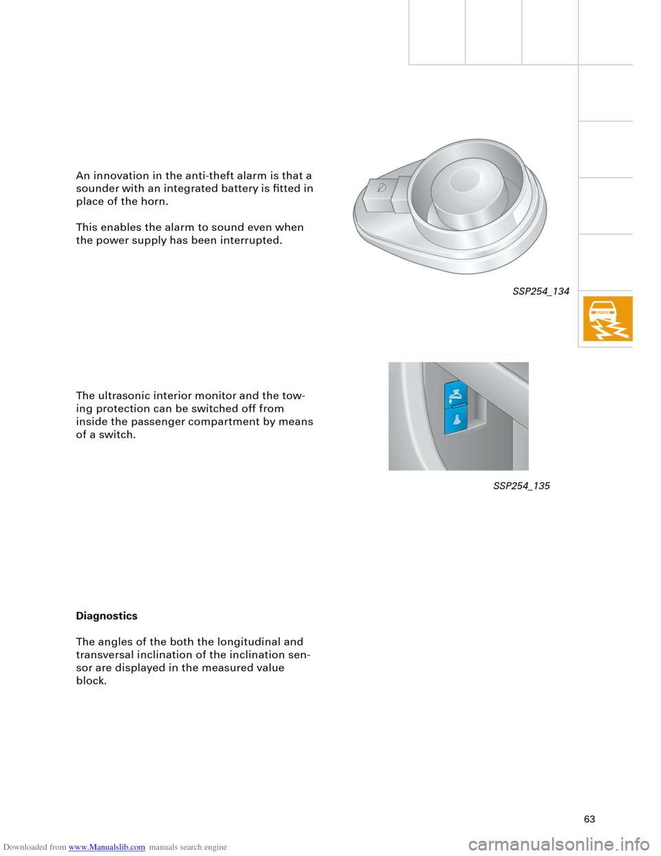
An innovation in the anti-theft alarm is that a
sounder with an integrated battery is fitted in
place of the horn.
This enables the alarm to sound even when
the power supply has been interrupted.
The ultrasonic interior monitor and the tow-
ing protection can be switched off from
inside the passenger compartment by means
of a switch.
Diagnostics
The angles of the both the longitudinal and
transversal inclination of the inclination sen-
sor are displayed in the measured value
block.
SSP254_134
SSP254_135