AUDI A4 2001 B5 / 1.G Technical Features Design And Function
Manufacturer: AUDI, Model Year: 2001,
Model line: A4,
Model: AUDI A4 2001 B5 / 1.G
Pages: 88, PDF Size: 10.42 MB
AUDI A4 2001 B5 / 1.G Technical Features Design And Function
A4 2001 B5 / 1.G
AUDI
AUDI
https://www.carmanualsonline.info/img/6/844/w960_844-0.png
AUDI A4 2001 B5 / 1.G Technical Features Design And Function
Trending: radiator, warning light, check engine light, radio, airbag off, fuel consumption, mileage
Page 81 of 88

Downloaded from www.Manualslib.com manuals search engine
81
Fresh air blower
Control technology has been integrated in the
new fresh air blower.
It includes the following features:
– Integrated control unit with diagnostic
capability via the operating and display
unit E87 (fault memory and measured
value block diagnosis-capable control
unit),
– optimised bearings for smoother running,
– separate solar input.
The required blower speed is calculated in the
operating and display unit E87, and requested
by the control unit for fresh air blower J126
via a PWM signal.In the case of malfunctions, such as e.g. a stiff
or blocked blower, this is signalled to the
operating and display unit E87 by duty cycle
changes based on the altered frequency. The
relevant fault is set.
The blower bearings have been re-engineered
in order to optimise the effectiveness of the
system.
This particularly benefits solar operation.
The energy supplied by the solar roof is
utilised to drive the fresh air blower by means
of special electronics via the separate solar
input in the blower.
SSP254_037
Page 82 of 88
Downloaded from www.Manualslib.com manuals search engine
82
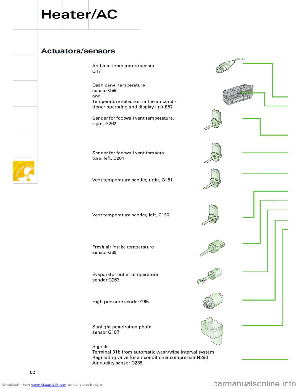
Actuators/sensors
Heater/AC
Ambient temperature sensor
G17
Dash panel temperature
sensor G56
and
Temperature selection in the air condi-
tioner operating and display unit E87
Sender for footwell vent temperature,
right, G262
Sender for footwell vent tempera-
ture, left, G261
High-pressure sender G65 Evaporator outlet temperature
sender G263 Fresh air intake temperature
sensor G89
Sunlight penetration photo-
sensor G107
Signals:
Terminal 31b from automatic wash/wipe interval system
Regulating valve for air conditioner compressor N280
Air quality sensor G238 Vent temperature sender, right, G151
Vent temperature sender, left, G150
E
C
O
NO
F
F
Page 83 of 88
Downloaded from www.Manualslib.com manuals search engine
83
153.95244km9:3628.07.2000
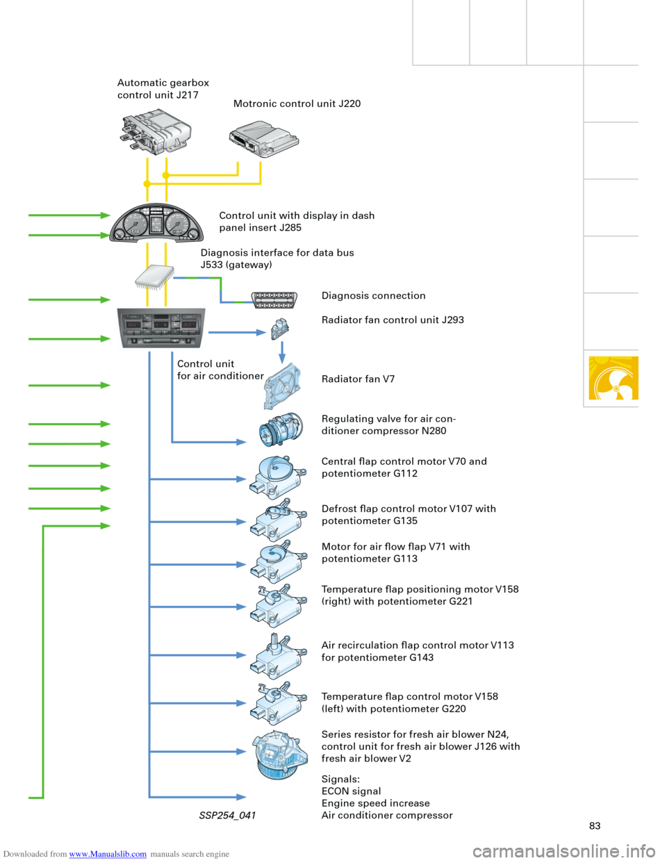
Diagnosis connection
Radiator fan control unit J293
Radiator fan V7
Regulating valve for air con-
ditioner compressor N280
Central flap control motor V70 and
potentiometer G112 Control unit
for air conditioner Automatic gearbox
control unit J217
Motronic control unit J220
Defrost flap control motor V107 with
potentiometer G135
Motor for air flow flap V71 with
potentiometer G113
Temperature flap positioning motor V158
(right) with potentiometer G221
Series resistor for fresh air blower N24,
control unit for fresh air blower J126 with
fresh air blower V2
Signals:
ECON signal
Engine speed increase
Air conditioner compressor Control unit with display in dash
panel insert J285
Diagnosis interface for data bus
J533 (gateway)
Air recirculation flap control motor V113
for potentiometer G143
Temperature flap control motor V158
(left) with potentiometer G220
SSP254_041
Page 84 of 88

Downloaded from www.Manualslib.com manuals search engine
84
Heater/AC
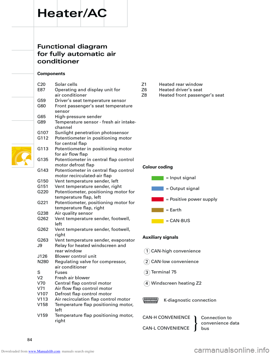
Functional diagram
for fully automatic air
conditioner
Components
C20 Solar cells
E87 Operating and display unit for
air conditioner
G59 Driver’s seat temperature sensor
G60 Front passenger’s seat temperature
sensor
G65 High-pressure sender
G89 Temperature sensor - fresh air intake-
channel
G107 Sunlight penetration photosensor
G112 Potentiometer in positioning motor
for central flap
G113 Potentiometer in positioning motor
for air flow flap
G135 Potentiometer in central flap control
motor defrost flap
G143 Potentiometer in central flap control
motor recirculated-air flap
G150 Vent temperature sender, left
G151 Vent temperature sender, right
G220 Potentiometer, positioning motor for
temperature flap, left
G221 Potentiometer, positioning motor for
temperature flap, right
G238 Air quality sensor
G262 Vent temperature sender, footwell,
left
G262 Vent temperature sender, footwell,
right
G263 Vent temperature sender, evaporator
J9 Relay for heated windscreen and
rear window
J126 Blower control unit
N280 Regulating valve for compressor,
air conditioner
S Fuses
V2 Fresh air blower
V70 Central flap control motor
V71 Air flow flap control motor
V107 Defrost flap control motor
V113 Air recirculation flap control motor
V158 Temperature flap positioning motor,
left
V159 Temperature flap positioning motor,
right
1
2
3
4CAN-high convenience
CAN-low convenience
Terminal 75
Windscreen heating Z2
K-diagnostic connection
CAN-H CONVENIENCE
CAN-L CONVENIENCEConnection to
convenience data
bus
Colour coding
= Input signal
= Output signal
= Positive power supply
= Earth
= CAN-BUS
Auxiliary signals
Z1 Heated rear window
Z6 Heated driver’s seat
Z8 Heated front passenger’s seat
{
Page 85 of 88
Downloaded from www.Manualslib.com manuals search engine 31
E87
Z1
V113 V107 V71 V70 G112 G113
M
M
G135 G143
31
N280
G238
G65
V2/J126
V159 V158
G220 G221G263 G262 G261 G89
t°
t°
t°
t°
4 3 J9
Z6
Z8
C20
in out
15
30
G107
G59 G150G60 G151
t°
t°
t°
t°
S1
5A
S26
30A
S44
30A
S25
30A
M
S6
5A
M
M
M
M
2
1
Page 86 of 88
Downloaded from www.Manualslib.com manuals search engine
86
+ -
K
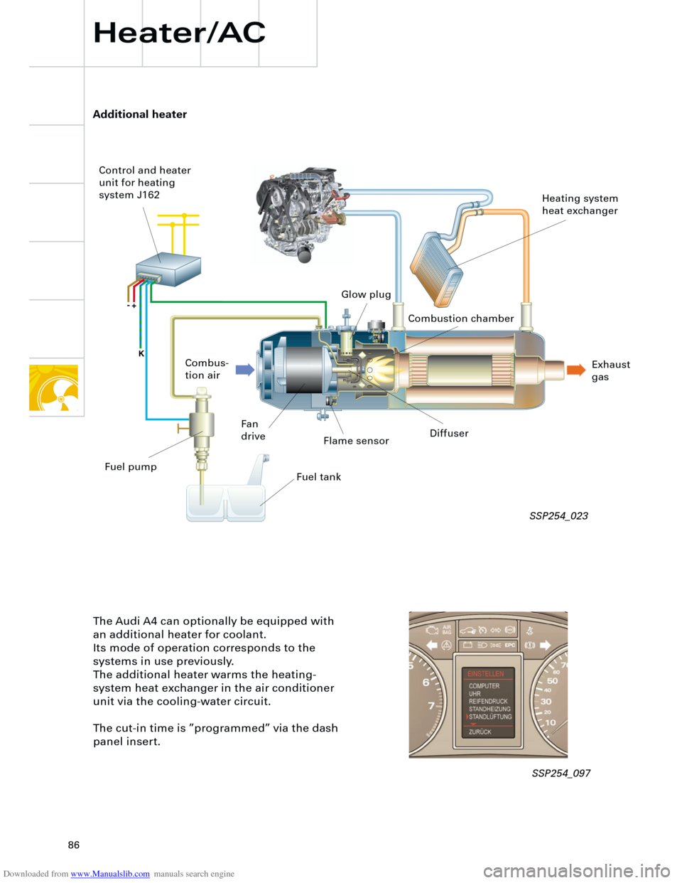
Additional heater
Heater/AC
The Audi A4 can optionally be equipped with
an additional heater for coolant.
Its mode of operation corresponds to the
systems in use previously.
The additional heater warms the heating-
system heat exchanger in the air conditioner
unit via the cooling-water circuit.
The cut-in time is ”programmed” via the dash
panel insert.
Flame sensor
Fan
driveDiffuser
Fuel tank Combus-
tion air Control and heater
unit for heating
system J162
Heating system
heat exchanger
Exhaust
gas Combustion chamber Glow plug
Fuel pump
SSP254_023
SSP254_097
Page 87 of 88
Downloaded from www.Manualslib.com manuals search engine
87
Page 88 of 88
Downloaded from www.Manualslib.com manuals search engine
Service.
For internal use only. All rights reserved, including the
right to make technical changes.
AUDI AG
Dept. I/VK-5
D-85045 Ingolstadt
Fax 0841/89-36367
040.2810.73.00
Technical status 10/00
Printed in Germany
AUDI A4´01 - Technical Features
Design and Function
Self-study programme 254
254
254
Trending: oil level, warning, alarm, torque, radio controls, length, seat memory


