bulb AUDI A4 2001 B5 / 1.G Technical Features Design And Function
[x] Cancel search | Manufacturer: AUDI, Model Year: 2001, Model line: A4, Model: AUDI A4 2001 B5 / 1.GPages: 88, PDF Size: 10.42 MB
Page 42 of 88
Downloaded from www.Manualslib.com manuals search engine
42
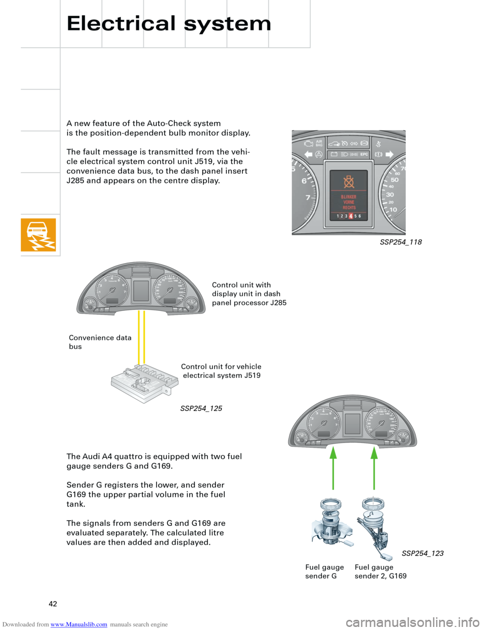
The Audi A4 quattro is equipped with two fuel
gauge senders G and G169.
Sender G registers the lower, and sender
G169 the upper partial volume in the fuel
tank.
The signals from senders G and G169 are
evaluated separately. The calculated litre
values are then added and displayed. A new feature of the Auto-Check system
is the position-dependent bulb monitor display.
The fault message is transmitted from the vehi-
cle electrical system control unit J519, via the
convenience data bus, to the dash panel insert
J285 and appears on the centre display.
Electrical system
Fuel gauge
sender 2, G169 Fuel gauge
sender G
SSP254_123
Control unit with
display unit in dash
panel processor J285
Control unit for vehicle
electrical system J519 Convenience data
bus
SSP254_118
SSP254_125
Page 50 of 88
Downloaded from www.Manualslib.com manuals search engine
50
Auxiliary signals
1 CAN high convenience
2 CAN low convenience
3 Terminal 75
4 not fitted with trailer coupling
5 only with trailer coupling
6 Automatic gearbox "multitronic"
7 Manual gearbox
A
U
X
Y
Z
Electrical system
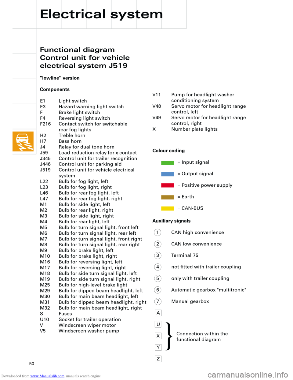
"lowline" version
Components
E1 Light switch
E3 Hazard warning light switch
F Brake light switch
F4 Reversing light switch
F216 Contact switch for switchable
rear fog lights
H2 Treble horn
H7 Bass horn
J4 Relay for dual tone horn
J59 Load-reduction relay for x contact
J345 Control unit for trailer recognition
J446 Control unit for parking aid
J519 Control unit for vehicle electrical
system
L22 Bulb for fog light, left
L23 Bulb for fog light, right
L46 Bulb for rear fog light, left
L47 Bulb for rear fog light, right
M1 Bulb for side light, left
M2 Bulb for rear light, right
M3 Bulb for side light, right
M4 Bulb for rear light, left
M5 Bulb for turn signal light, front left
M6 Bulb for turn signal light, rear left
M7 Bulb for turn signal light, front right
M8 Bulb for turn signal light, rear right
M9 Bulb for brake light, left
M10 Bulb for brake light, right
M16 Bulb for reversing light, left
M17 Bulb for reversing light, right
M18 Bulb for side turn signal light, left
M19 Bulb for side turn signal light, right
M25 Bulb for high-level brake light
M29 Bulb for dipped beam headlight, left
M30 Bulb for main beam headlight, left
M31 Bulb for dipped beam headlight, right
M32 Bulb for main beam headlight, right
S Fuses
U10 Socket for trailer operation
V Windscreen wiper motor
V5 Windscreen washer pump
Colour coding
= Input signal
= Output signal
= Positive power supply
= Earth
= CAN-BUS
V11 Pump for headlight washer
conditioning system
V48 Servo motor for headlight range
control, left
V49 Servo motor for headlight range
control, right
X Number plate lights
Connection within the
functional diagram
Functional diagram
Control unit for vehicle
electrical system J519
{
Page 52 of 88
Downloaded from www.Manualslib.com manuals search engine
52
Auxiliary signals
1 CAN high convenience
2 CAN low convenience
3 Terminal 75
4 Terminal 31
U Connection within the functional
diagram V11 Pump for headlight washer
conditioning system
V48 Servo motor for headlight range
control, left
V49 Servo motor for headlight range
control, right
X Number plate light
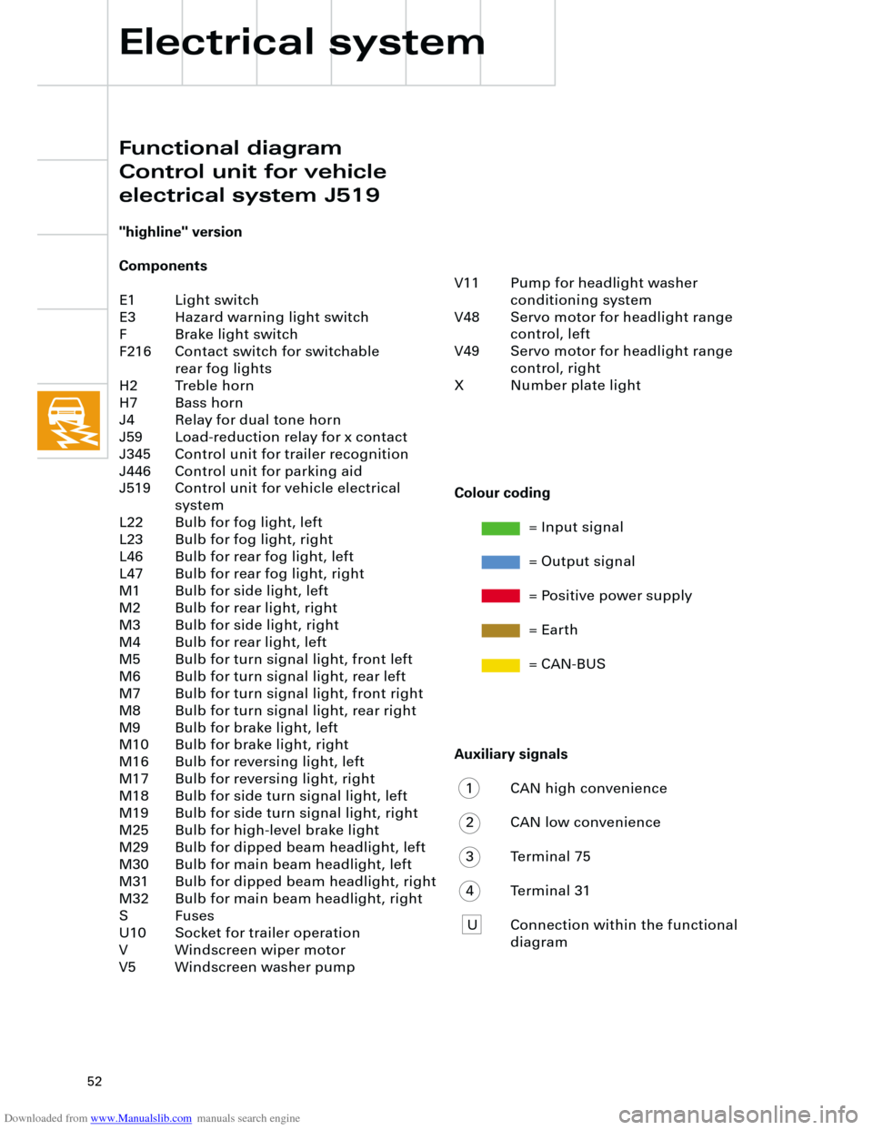
"highline" version
Components
E1 Light switch
E3 Hazard warning light switch
F Brake light switch
F216 Contact switch for switchable
rear fog lights
H2 Treble horn
H7 Bass horn
J4 Relay for dual tone horn
J59 Load-reduction relay for x contact
J345 Control unit for trailer recognition
J446 Control unit for parking aid
J519 Control unit for vehicle electrical
system
L22 Bulb for fog light, left
L23 Bulb for fog light, right
L46 Bulb for rear fog light, left
L47 Bulb for rear fog light, right
M1 Bulb for side light, left
M2 Bulb for rear light, right
M3 Bulb for side light, right
M4 Bulb for rear light, left
M5 Bulb for turn signal light, front left
M6 Bulb for turn signal light, rear left
M7 Bulb for turn signal light, front right
M8 Bulb for turn signal light, rear right
M9 Bulb for brake light, left
M10 Bulb for brake light, right
M16 Bulb for reversing light, left
M17 Bulb for reversing light, right
M18 Bulb for side turn signal light, left
M19 Bulb for side turn signal light, right
M25 Bulb for high-level brake light
M29 Bulb for dipped beam headlight, left
M30 Bulb for main beam headlight, left
M31 Bulb for dipped beam headlight, right
M32 Bulb for main beam headlight, right
S Fuses
U10 Socket for trailer operation
V Windscreen wiper motor
V5 Windscreen washer pump
Electrical system
Colour coding
= Input signal
= Output signal
= Positive power supply
= Earth
= CAN-BUS
Functional diagram
Control unit for vehicle
electrical system J519
Page 54 of 88
Downloaded from www.Manualslib.com manuals search engine
54
5 V/Div.=10 ms/Div.
0 T
Electrical system
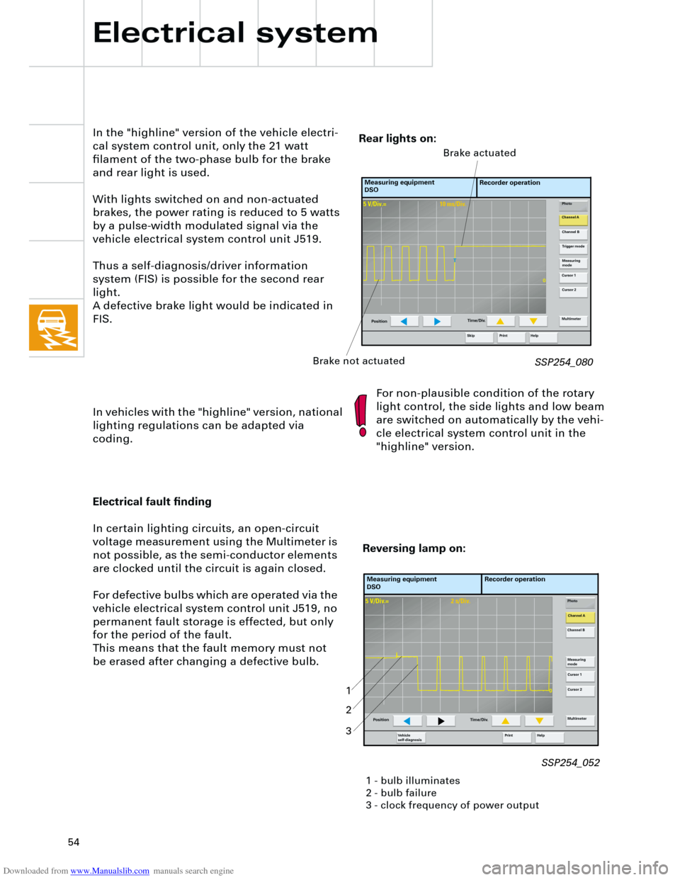
In the "highline" version of the vehicle electri-
cal system control unit, only the 21 watt
filament of the two-phase bulb for the brake
and rear light is used.
With lights switched on and non-actuated
brakes, the power rating is reduced to 5 watts
by a pulse-width modulated signal via the
vehicle electrical system control unit J519.
Thus a self-diagnosis/driver information
system (FIS) is possible for the second rear
light.
A defective brake light would be indicated in
FIS.
In vehicles with the "highline" version, national
lighting regulations can be adapted via
coding.For non-plausible condition of the rotary
light control, the side lights and low beam
are switched on automatically by the vehi-
cle electrical system control unit in the
"highline" version.
SSP254_080
Measuring equipment
DSORecorder operation
Photo
Channel A
Channel B
Measuring
mode
Cursor 1
Cursor 2
Multimeter
Help Print
PositionTime/Div.
Trigger mode
Skip
Brake not actuatedBrake actuated
Rear lights on:
5 V/Div.=2 s/Div.
0
Electrical fault finding
In certain lighting circuits, an open-circuit
voltage measurement using the Multimeter is
not possible, as the semi-conductor elements
are clocked until the circuit is again closed.
For defective bulbs which are operated via the
vehicle electrical system control unit J519, no
permanent fault storage is effected, but only
for the period of the fault.
This means that the fault memory must not
be erased after changing a defective bulb.
Measuring equipment
DSORecorder operation
Photo
Channel A
Channel B
Measuring
mode
Cursor 1
Cursor 2
Multimeter
Help Print Ve h i c l e
self-diagnosis
Position Time/Div.
Reversing lamp on:
1 - bulb illuminates
2 - bulb failure
3 - clock frequency of power output
1
2
3
SSP254_052
Page 55 of 88
Downloaded from www.Manualslib.com manuals search engine
55
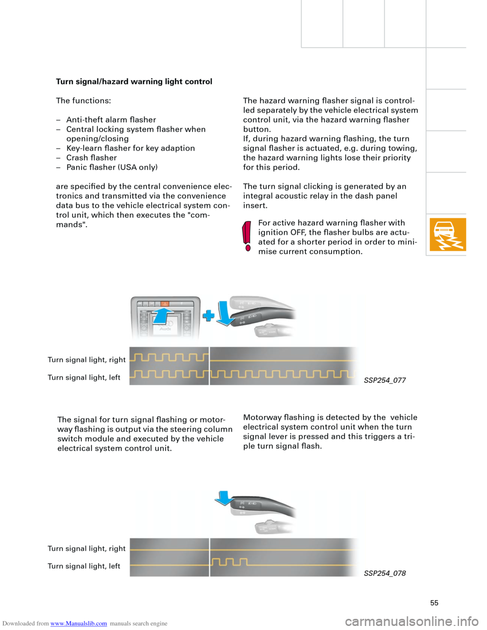
The hazard warning flasher signal is control-
led separately by the vehicle electrical system
control unit, via the hazard warning flasher
button.
If, during hazard warning flashing, the turn
signal flasher is actuated, e.g. during towing,
the hazard warning lights lose their priority
for this period.
The turn signal clicking is generated by an
integral acoustic relay in the dash panel
insert.
Turn signal/hazard warning light control
The functions:
– Anti-theft alarm flasher
– Central locking system flasher when
opening/closing
– Key-learn flasher for key adaption
– Crash flasher
– Panic flasher (USA only)
are specified by the central convenience elec-
tronics and transmitted via the convenience
data bus to the vehicle electrical system con-
trol unit, which then executes the "com-
mands".
The signal for turn signal flashing or motor-
way flashing is output via the steering column
switch module and executed by the vehicle
electrical system control unit.
For active hazard warning flasher with
ignition OFF, the flasher bulbs are actu-
ated for a shorter period in order to mini-
mise current consumption.
Motorway flashing is detected by the vehicle
electrical system control unit when the turn
signal lever is pressed and this triggers a tri-
ple turn signal flash.
Turn signal light, right
Turn signal light, left
Turn signal light, right
Turn signal light, left
SSP254_077
SSP254_078