steering AUDI A4 2001 B5 / 1.G Technical Features Design And Function
[x] Cancel search | Manufacturer: AUDI, Model Year: 2001, Model line: A4, Model: AUDI A4 2001 B5 / 1.GPages: 88, PDF Size: 10.42 MB
Page 2 of 88
Downloaded from www.Manualslib.com manuals search engine
2
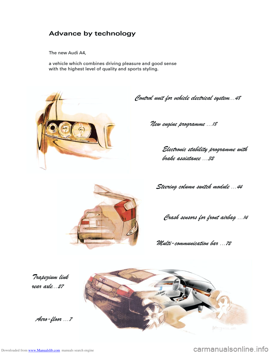
Advance by technology
The new Audi A4,
a vehicle which combines driving pleasure and good sense
with the highest level of quality and sports styling.
Control unit for vehicle electrical system
...48
New engine programme
...18
Electronic stability programme with
brake assistance
...32
Steering column switch module
...44
Crash sensors for front airbag
...14
Multi-communication bar
...72
Trapezium link
rear axle
...27
Aero-floor
...7
Page 3 of 88
Downloaded from www.Manualslib.com manuals search engine
3
Important:
Note
New
Contents
It is not intended as a workshop manual.
The self-study programme will provide you with information on
design and functions.
For maintenance and repair operations it is essential that you
refer to the current technical literature.
Page
Introduction . . . . . . . . . . . . . . . . . . . . . . . . . . . . . . . . . . . . . . . . . . 4
Body . . . . . . . . . . . . . . . . . . . . . . . . . . . . . . . . . . . . . . . . . . . . . . . . 8
Occupant protection . . . . . . . . . . . . . . . . . . . . . . . . . . . . . . . . 12
Engine and gearbox
Running gear
Axles . . . . . . . . . . . . . . . . . . . . . . . . . . . . . . . . . . . . . . . . . . . . . . . . . . . . . . . . . . . . 26
Mechanical unit mountings . . . . . . . . . . . . . . . . . . . . . . . . . . . . . . . . . . . . . . . . . . . 28
Brake system . . . . . . . . . . . . . . . . . . . . . . . . . . . . . . . . . . . . . . . . . . . . . . . . . . . . . . . 29
Brake assistance . . . . . . . . . . . . . . . . . . . . . . . . . . . . . . . . . . . . . . . . . . . . . . . . . . . . 32
Vehicle electrical system . . . . . . . . . . . . . . . . . . . . . . . . . . . . . . . . . . . . . . . . . . . . . . 36
CAN BUS system . . . . . . . . . . . . . . . . . . . . . . . . . . . . . . . . . . . . . . . . . . . . . . . . . . . . 38
Dash panel insert . . . . . . . . . . . . . . . . . . . . . . . . . . . . . . . . . . . . . . . . . . . . . . . . . . . . 40
Steering column switch module . . . . . . . . . . . . . . . . . . . . . . . . . . . . . . . . . . . . . . . .44
Function circuit diagram . . . . . . . . . . . . . . . . . . . . . . . . . . . . . . . . . . . . . . . 46
Control unit for vehicle electrical system . . . . . . . . . . . . . . . . . . . . . . . . . . . . . . . . 48
Function circuit diagram for "lowline" version . . . . . . . . . . . . . . . . . . . . . 50
Function circuit diagram for "highline" version . . . . . . . . . . . . . . . . . . . . 52
Convenience system . . . . . . . . . . . . . . . . . . . . . . . . . . . . . . . . . . . . . . . . . . . . . . . . . 58
Anti-theft alarm system . . . . . . . . . . . . . . . . . . . . . . . . . . . . . . . . . . . . . . . . . . . . . . . 63
Radio - chorus II, concert II and symphony II . . . . . . . . . . . . . . . . . . . . . . . . . . . . . 65
Navigation IV and Navigation Plus-D . . . . . . . . . . . . . . . . . . . . . . . . . . . . . . . . . . . . 69
Multi-communication bar . . . . . . . . . . . . . . . . . . . . . . . . . . . . . . . . . . . . . . . . . . . . . 72
Electric logbook "Audi Logbook" . . . . . . . . . . . . . . . . . . . . . . . . . . . . . . . . . . . . . . . 74
Heater/AC
Design and function . . . . . . . . . . . . . . . . . . . . . . . . . . . . . . . . . . . . . . . . . . . . . . . . . 76
7-piston compressor . . . . . . . . . . . . . . . . . . . . . . . . . . . . . . . . . . . . . . . . . . . . . . . . . 77
Air conditioner . . . . . . . . . . . . . . . . . . . . . . . . . . . . . . . . . . . . . . . . . . . . . . . . . . . . . . 78
Glove compartment cooling . . . . . . . . . . . . . . . . . . . . . . . . . . . . . . . . . . . . . . . . . . . 79
Solar roof . . . . . . . . . . . . . . . . . . . . . . . . . . . . . . . . . . . . . . . . . . . . . . . . . . . . . . . . . . . 80
Fresh air blower . . . . . . . . . . . . . . . . . . . . . . . . . . . . . . . . . . . . . . . . . . . . . . . . . . . . . 81
Actuators/sensors . . . . . . . . . . . . . . . . . . . . . . . . . . . . . . . . . . . . . . . . . . . . . . . . . . . 82
Functional diagram for fully automatic air conditioner . . . . . . . . . . . . . . 84
Additional heater . . . . . . . . . . . . . . . . . . . . . . . . . . . . . . . . . . . . . . . . . . . . . . . . . . . . 86 2.0 l R4 and 3.0 l V6 engines (see SSP 255) . . . . . . . . . . . . . . . . . . . . . . . . . . . . . . . 18
Innovations - 2.5 l V6 TDI engine. . . . . . . . . . . . . . . . . . . . . . . . . . . . . . . . . . . . . . . . 19
Innovations - automatic gearbox . . . . . . . . . . . . . . . . . . . . . . . . . . . . . . . . . . . . . . . 23
Electrical system
Page 14 of 88
Downloaded from www.Manualslib.com manuals search engine
14
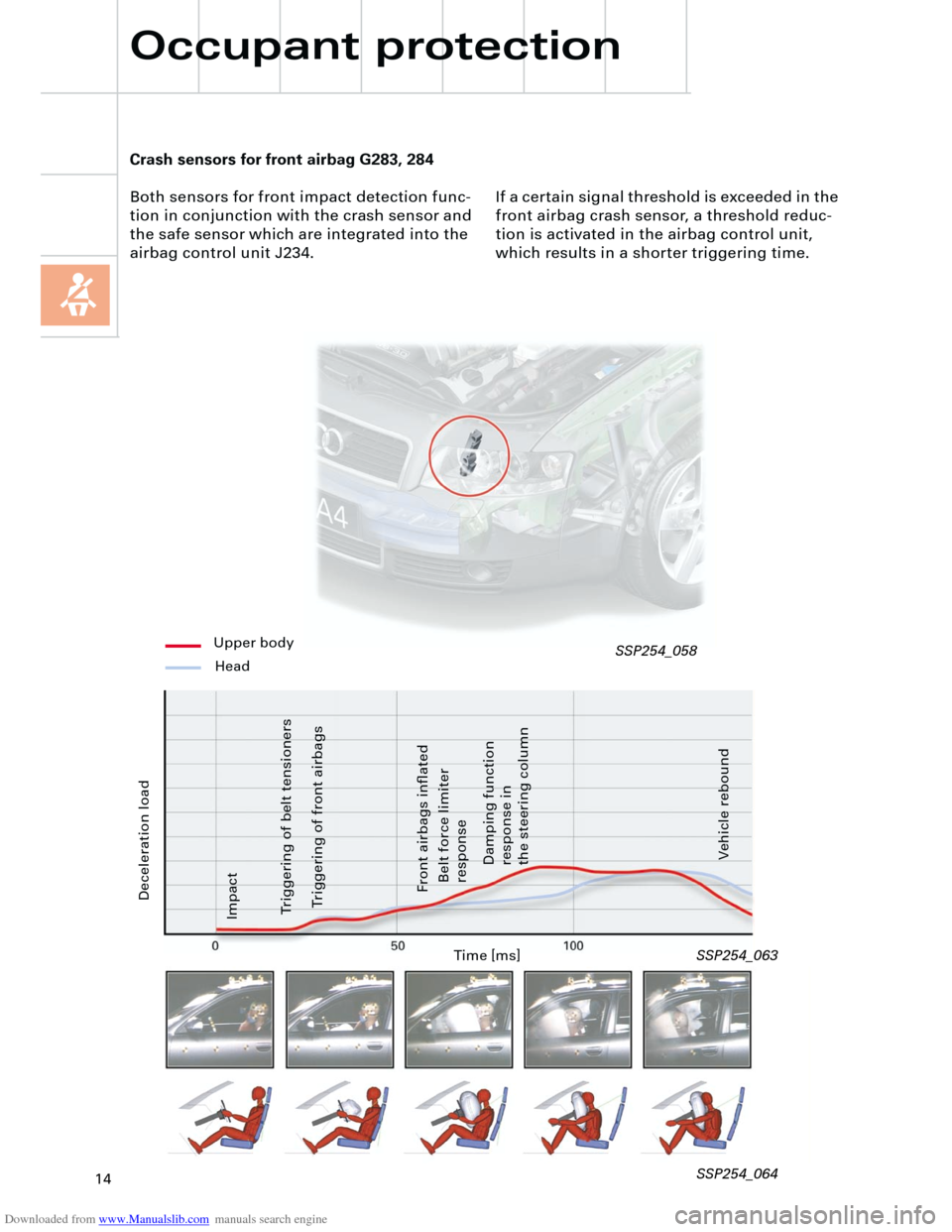
Crash sensors for front airbag G283, 284
Both sensors for front impact detection func-
tion in conjunction with the crash sensor and
the safe sensor which are integrated into the
airbag control unit J234.
Deceleration load
Time [ms]
Vehicle rebound Impact
Triggering of belt tensioners
Triggering of front airbags
Front airbags inflated
Belt force limiter
response
Damping function
response in
the steering column
SSP254_063
SSP254_064
Upper body
Head
If a certain signal threshold is exceeded in the
front airbag crash sensor, a threshold reduc-
tion is activated in the airbag control unit,
which results in a shorter triggering time.
Occupant protection
SSP254_058
Page 23 of 88
Downloaded from www.Manualslib.com manuals search engine
23
P
R+NDS
Innovations - automatic
gearbox
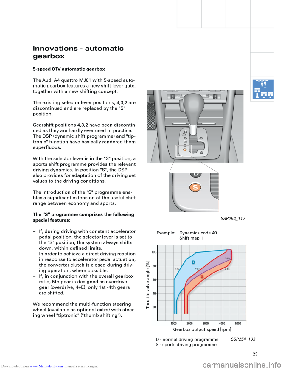
5-speed 01V automatic gearbox
The Audi A4 quattro MJ01 with 5-speed auto-
matic gearbox features a new shift lever gate,
together with a new shifting concept.
The existing selector lever positions, 4,3,2 are
discontinued and are replaced by the "S"
position.
Gearshift positions 4,3,2 have been discontin-
ued as they are hardly ever used in practice.
The DSP (dynamic shift programme) and "tip-
tronic" function have basically rendered them
superfluous.
With the selector lever is in the "S" position, a
sports shift programme provides the relevant
driving dynamics. In position "S", the DSP
also provides for adaptation of the driving set
values to the driving conditions.
The introduction of the "S" programme ena-
bles a significant extension of the useful shift
range between economy and sports.
The "S" programme comprises the following
special features:
– If, during driving with constant accelerator
pedal position, the selector lever is set to
the "S" position, the system always shifts
down, within defined limits.
– In order to achieve a direct driving reaction
in response to accelerator pedal actuation,
the converter clutch is closed during driv-
ing operation, where possible.
– If, in conjunction with the overall gearbox
ratio, 5th gear is designed as overdrive
gear (overdrive, 4+E), only 1st -4th gears
are shifted.
We recommend the multi-function steering
wheel (available as optional extra) with steer-
ing wheel "tiptronic" ("thumb shifting").
Gearbox output speed [rpm]
Throttle valve angle [%]
SSP254_103 SSP254_117
D - normal driving programme
S - sports driving programmeExample: Dynamics code 40
Shift map 1
Page 24 of 88
Downloaded from www.Manualslib.com manuals search engine
24
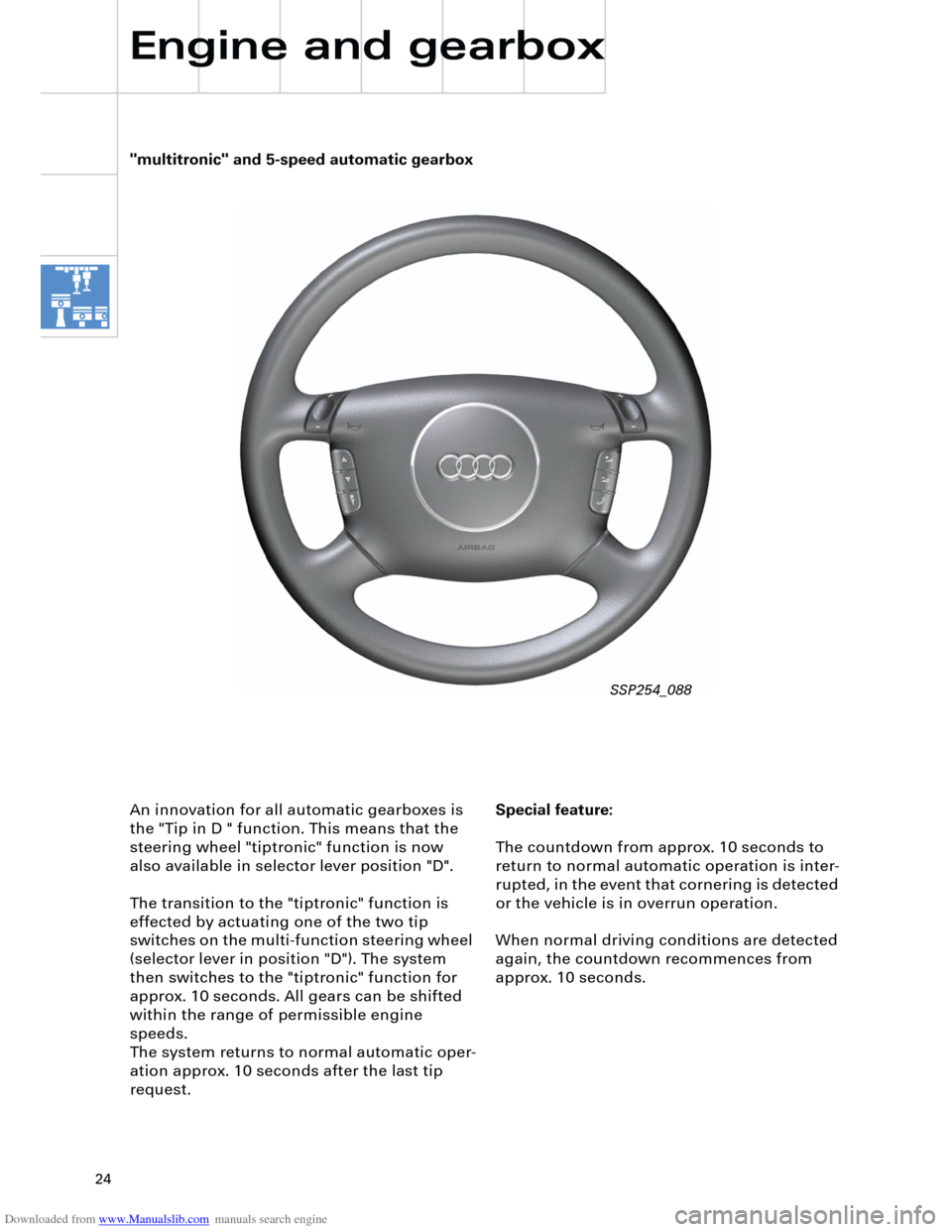
Special feature:
The countdown from approx. 10 seconds to
return to normal automatic operation is inter-
rupted, in the event that cornering is detected
or the vehicle is in overrun operation.
When normal driving conditions are detected
again, the countdown recommences from
approx. 10 seconds. An innovation for all automatic gearboxes is
the "Tip in D " function. This means that the
steering wheel "tiptronic" function is now
also available in selector lever position "D".
The transition to the "tiptronic" function is
effected by actuating one of the two tip
switches on the multi-function steering wheel
(selector lever in position "D"). The system
then switches to the "tiptronic" function for
approx. 10 seconds. All gears can be shifted
within the range of permissible engine
speeds.
The system returns to normal automatic oper-
ation approx. 10 seconds after the last tip
request.
Engine and gearbox
"multitronic" and 5-speed automatic gearbox
SSP254_088
Page 36 of 88
Downloaded from www.Manualslib.com manuals search engine
36
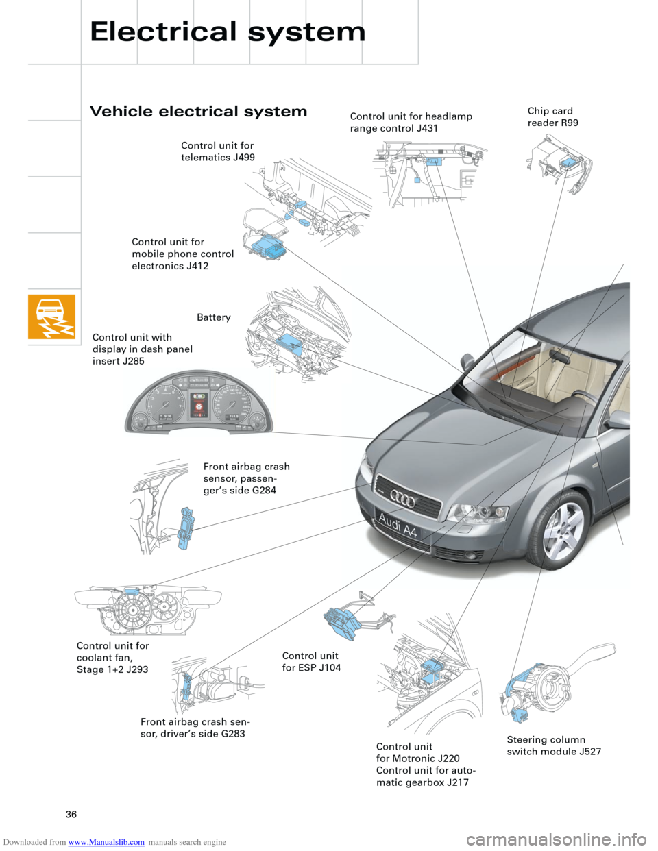
Front airbag crash sen-
sor, driver’s side G283
Vehicle electrical system
Electrical system
Control unit for
coolant fan,
Stage 1+2 J293Control unit
for ESP J104 Control unit for
telematics J499
Control unit for
mobile phone control
electronics J412
Front airbag crash
sensor, passen-
ger’s side G284
Control unit
for Motronic J220
Control unit for auto-
matic gearbox J217
Control unit for headlamp
range control J431Chip card
reader R99
Steering column
switch module J527
Battery
Control unit with
display in dash panel
insert J285
Page 38 of 88
Downloaded from www.Manualslib.com manuals search engine
38
Electrical system
NOX sensor
(USA only) Diagnosis system
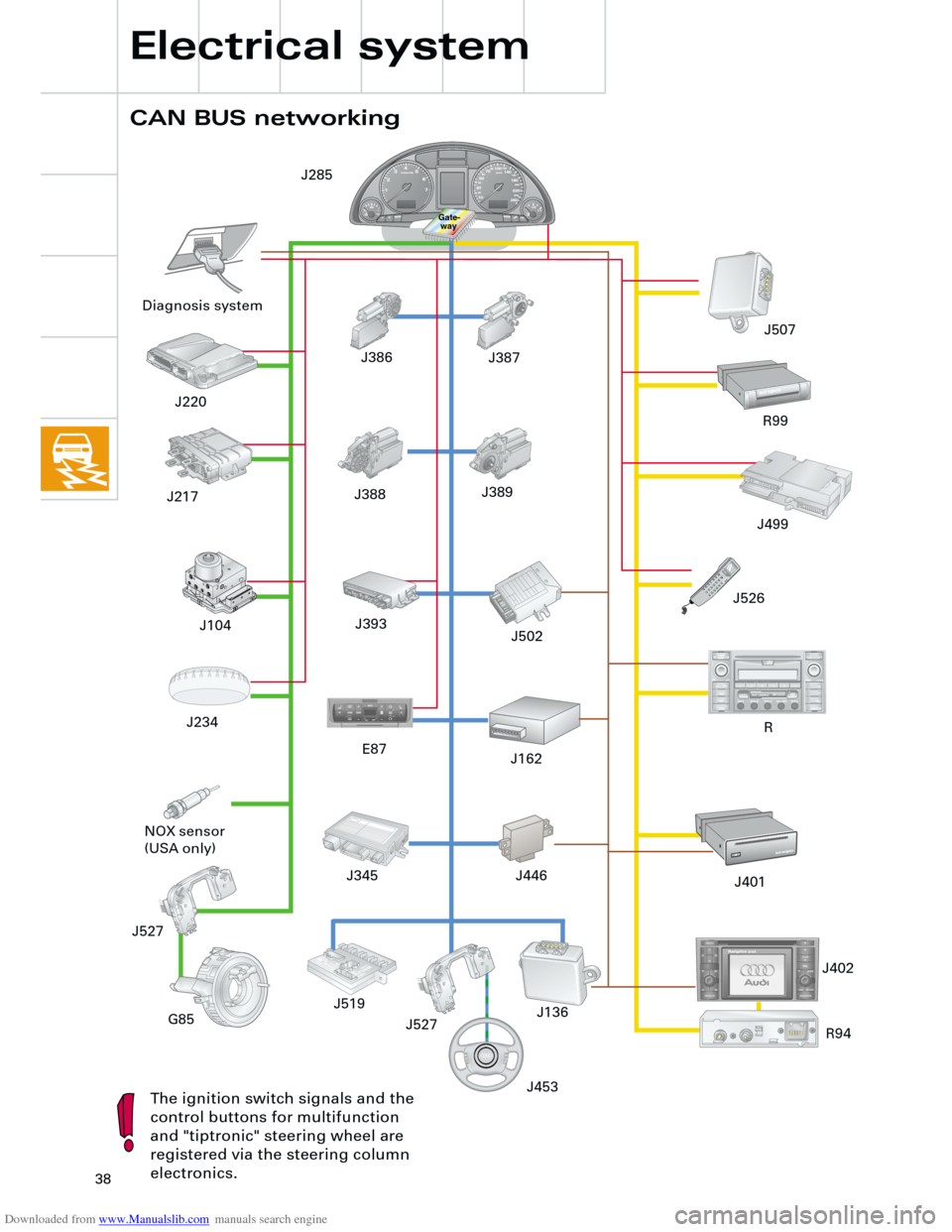
CAN BUS networking
The ignition switch signals and the
control buttons for multifunction
and "tiptronic" steering wheel are
registered via the steering column
electronics.
G85
J162J502
R99
J401
Gate-
way
J220
J234
J387 J386
J388 J389
J393 J217
J104
J453 J446
J402 E87
J519
J136 J345J526J499 J507
J527
J285
R94
TRACK
SEEK
CD CDC
AM
FM1DOLBY SYSTEM2
12
TA P EPLAY SDEBASS MIDDLE TREBLE BALANCE FADER123456
EJECTAudi symphony
AS
TP
RDS
RANDOM FR FF
TUNE SCAN
EJECT
R
J527
R
T+-
Page 39 of 88
Downloaded from www.Manualslib.com manuals search engine
39
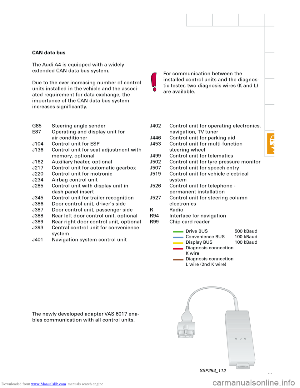
CAN data bus
The Audi A4 is equipped with a widely
extended CAN data bus system.
Due to the ever increasing number of control
units installed in the vehicle and the associ-
ated requirement for data exchange, the
importance of the CAN data bus system
increases significantly.For communication between the
installed control units and the diagnos-
tic tester, two diagnosis wires (K and L)
are available.
The newly developed adapter VAS 6017 ena-
bles communication with all control units.
Drive BUS 500 kBaud
Convenience BUS 100 kBaud
Display BUS 100 kBaud
Diagnosis connection
K wire
Diagnosis connection
L wire (2nd K wire)
J402 Control unit for operating electronics,
navigation, TV tuner
J446 Control unit for parking aid
J453 Control unit for multi-function
steering wheel
J499 Control unit for telematics
J502 Control unit for tyre pressure monitor
J507 Control unit for speech entry
J519 Control unit for vehicle electrical
system
J526 Control unit for telephone -
permanent installation
J527 Control unit for steering column
electronics
R Radio
R94 Interface for navigation
R99 Chip card reader G85 Steering angle sender
E87 Operating and display unit for
air conditioner
J104 Control unit for ESP
J136 Control unit for seat adjustment with
memory, optional
J162 Auxiliary heater, optional
J217 Control unit for automatic gearbox
J220 Control unit for motronic
J234 Airbag control unit
J285 Control unit with display unit in
dash panel insert
J345 Control unit for trailer recognition
J386 Door control unit, driver’s side
J387 Door control unit, passenger side
J388 Rear left door control unit, optional
J389 Rear right door control unit, optional
J393 Central control unit for convenience
system
J401 Navigation system control unit
SSP254_112
Page 43 of 88
Downloaded from www.Manualslib.com manuals search engine
43
A further innovation is the display of the max-
imum and minimum engine oil levels in the
measured value block after the most recent
service operation.
The adaptation of the mileage/kilometre read-
ing after replacement of the dash panel
insert, is possible (several attempts) up to a
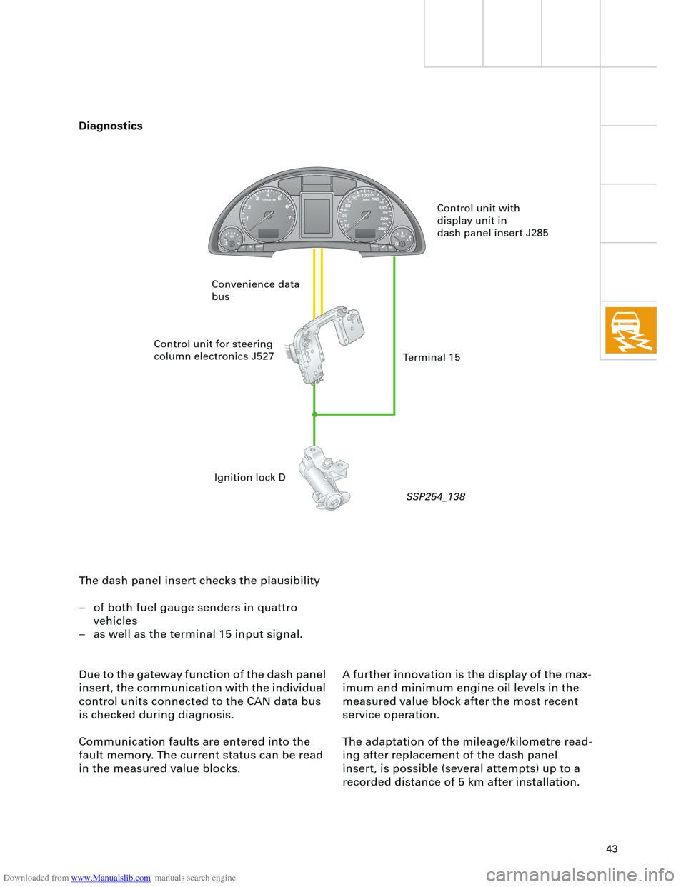
recorded distance of 5 km after installation. The dash panel insert checks the plausibility
– of both fuel gauge senders in quattro
vehicles
– as well as the terminal 15 input signal.
Due to the gateway function of the dash panel
insert, the communication with the individual
control units connected to the CAN data bus
is checked during diagnosis.
Communication faults are entered into the
fault memory. The current status can be read
in the measured value blocks.
Control unit with
display unit in
dash panel insert J285
Control unit for steering
column electronics J527
Ignition lock D Convenience data
bus
Terminal 15
Diagnostics
SSP254_138
Page 44 of 88
Downloaded from www.Manualslib.com manuals search engine
44
Electrical system
Steering column switch
module
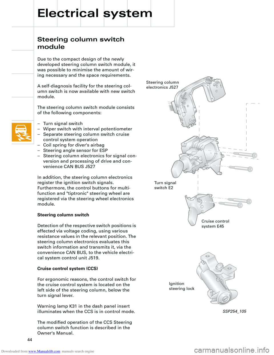
Due to the compact design of the newly
developed steering column switch module, it
was possible to minimise the amount of wir-
ing necessary and the space requirements.
A self-diagnosis facility for the steering col-
umn switch is now available with new switch
module.
The steering column switch module consists
of the following components:
– Turn signal switch
– Wiper switch with interval potentiometer
– Separate steering column switch cruise
control system operation
– Coil spring for diver's airbag
– Steering angle sensor for ESP
– Steering column electronics for signal con-
version and processing of drive and con-
venience CAN BUS J527
In addition, the steering column electronics
register the ignition switch signals.
Furthermore, the control buttons for multi-
function and "tiptronic" steering wheel are
registered via the steering wheel electronics
module.
Steering column switch
Detection of the respective switch positions is
effected via voltage coding, using various
resistance values in the relevant position. The
steering column electronics evaluates this
switch information and transmits it, via the
convenience CAN BUS, to the vehicle electri-
cal system control unit J519.
Cruise control system (CCS)
For ergonomic reasons, the control switch for
the cruise control system is located on the
left side of the steering column, below the
turn signal lever.
Warning lamp K31 in the dash panel insert
illuminates when the CCS is in control mode.
The modified operation of the CCS Steering
column switch function is described in the
Owner's Manual.
Cruise control
system E45
Ignition
steering lock Steering column
electronics J527
Turn signal
switch E2
SSP254_105