Plug AUDI A4 2008 B8 / 4.G User Guide
[x] Cancel search | Manufacturer: AUDI, Model Year: 2008, Model line: A4, Model: AUDI A4 2008 B8 / 4.GPages: 342, PDF Size: 13.14 MB
Page 289 of 342
Self-help287
Controls
Safety
Driving tips
General maintenance
Self-help
Technical data
– Check whether a repair is possible using the Tyre
Mobility System ⇒page 285.
– Ensure that all passengers leave the vehicle and move
away from the danger area ⇒.
– Take the tyre sealant can and the electric compressor out
of the luggage compartment ⇒page 283.
– Fix the sticker “max. 80 km/h”, which is included with the
tyre sealant can, onto the instrument cluster where the
driver will see it.
Filling the tyre
– Shake the tyre sealant can well.
– Screw the enclosed filling hose onto the sealant can as
far as it will go. This will automatically pierce the foil
sealing the can.
– Take the valve cap off the tyre valve and use the enclosed
valve insert tool to unscrew the valve insert ⇒page 286,
fig. 270.
– Place the valve insert onto a clean surface.
– Remove the sealing plug from the filling hose and insert
the hose into the tyre valve.
– Hold the tyre sealant can upside down and fill the
complete contents of the can into the tyre.
– Then disconnect the hose and screw the valve insert
firmly back into the tyre valve.Inflating the tyre
– Screw the filling hose of the electric compressor onto the
tyre valve and plug the connector into the cigarette
lighter.
– Pump the tyre up to 2.0 to 2.5 bar and monitor the pres-
sure shown on the pressure gauge.
– If the tyre pressure remains lower than the value speci-
fied above drive the vehicle approx. 10 metres forwards
or backwards, so that the sealant can spread evenly in
the tyre. If the pressure is still lower than the specifica-
tion the tyre is too badly damaged and cannot be
repaired using the tyre sealant.
Final checks
– After about 10 minutes stop to check the tyre pressure.
– If tyre pressure is less than 1.3 bar, the tyre is too badly
damaged. Do not drive on. You should obtain profes-
sional assistance.
WARNING
•
If you have a puncture in moving traffic, switch on the hazard
warning lights and place the warning triangle in a visible location.
This is for your own safety and also warns other road users.
•
Make sure your passengers wait in a safe place (for instance
behind the roadside crash barrier).
•
Please observe the manufacturers' safety notes on the
compressor and the instructions supplied with the tyre sealant
can.
•
If it was not possible to build up a tyre pressure of 2.0 bar
within 6 minutes this means that the tyre is too badly damaged.
Do not drive on.
document_0900452a81b1b9de.book Seite 287 Donnerstag, 26. Juli 2007 9:16 09
Page 297 of 342
Self-help295
Controls
Safety
Driving tips
General maintenance
Self-help
Technical data terminal must not touch metal parts of the vehicle: this can cause
short circuiting.
•
Do not bend over the batteries – risk of acid burns.
•
The screw plugs on the battery cells must be screwed in firmly.
•
Keep sparks, flame and lighted cigarettes away from batteries:
the gases given off can cause an explosion.
•
If jump-starting another vehicle, position the jump leads in
such a way that they cannot come into contact with any moving
parts in the engine compartment of the other vehicle.Caution
Please note that the above method of connecting the leads is meant
for jump-starting your vehicle. If jump-starting another vehicle, you
should not connect the negative lead (–) to the negative terminal of
the discharged battery, but directly to the engine block or a solid
metal part bolted to the engine block. If the battery of the other
vehicle does not have a gas vent, there is a risk that a mixture of
oxygen and hydrogen gas can accumulate and cause an
explosion.Tow-starting and towing awayGeneral notes
Points to observe when tow-starting or towing awayIf you use a towrope:
Notes for the driver of the towing vehicle
– The towrope must be taut before driving off.– Engage the clutch very gently when starting to move; on
vehicles with automatic gearbox press the accelerator
slowly.
Notes for the driver of the towed vehicle
– The ignition should be switched on so that the turn
signals, horn, windscreen wipers and washers can be
used. Please ensure that the steering wheel is unlocked
when you switch on the ignition, and that it moves freely.
–Put gear lever in neutral (manual gearbox) or move
selector lever to position N (automatic gearbox).
– The brake servo and power steering only work when the
engine is running. Considerably more effort is required
on the brake pedal and steering wheel when the engine
is switched off.
– Ensure that the towrope remains taut at all times when
towing.
Towrope or towbar
It is easier and safer to tow a vehicle with a towbar. You should only
use a towrope if you do not have a towbar.
A towrope should be slightly elastic to reduce the loading on both
vehicles. It is advisable to use a towrope made of synthetic fibre or
similar material.
Attach the tow-rope or tow-bar only to the towing anchorages
intended for this purpose ⇒page 296 or ⇒page 297.
Driving technique
Towing requires some experience – especially when using a
towrope. Both drivers should be familiar with the technique required
for towing. Inexperienced drivers should not attempt to tow-start or
tow away another vehicle.
WARNING (continued)
document_0900452a81b1b9de.book Seite 295 Donnerstag, 26. Juli 2007 9:16 09
Page 309 of 342
Fuses and bulbs307
Controls
Safety
Driving tips
General maintenance
Self-help
Technical data
– Take the screwdriver and the interchangeable Torx socket
out of the vehicle tool kit.
– Remove the screws ⇒page 306, fig. 288 that secure the
trim panel to the lock carrier and detach the trim panel.
– Slacken the two screws that secure the headlight to the
lock carrier and the two screws at the underside of the
headlight (the screws at the underside should not be
slackened more than five turns) ⇒page 306, fig. 289.
– Carefully pull the headlight forward about 60 mm.
– Release and unplug the electrical connector.
– Carefully take the headlight out towards the front (swivel
it slightly if necessary).
Installing
– Perform all of the above steps in reverse sequence.The headlight must be inserted in two guides (on the underside of
the headlight). This is the only way to ensure that the headlight is
installed in the correct position. To determine whether the headlight
is correctly installed, check that it is aligned flush with adjacent
body parts (such as the wing panel).
Do not interchange the securing screws.
Caution
Please take particular care not to damage or scratch the adjacent
parts of the body when removing or installing the headlights.
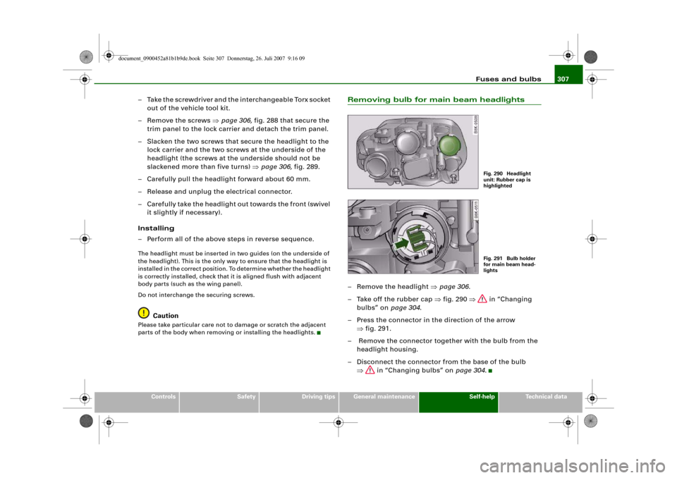
Removing bulb for main beam headlights– Remove the headlight ⇒page 306.
– Take off the rubber cap ⇒fig. 290 ⇒ in “Changing
bulbs” on page 304.
– Press the connector in the direction of the arrow
⇒fig. 291.
– Remove the connector together with the bulb from the
headlight housing.
– Disconnect the connector from the base of the bulb
⇒ in “Changing bulbs” on page 304.
Fig. 290 Headlight
unit: Rubber cap is
highlightedFig. 291 Bulb holder
for main beam head-
lights
document_0900452a81b1b9de.book Seite 307 Donnerstag, 26. Juli 2007 9:16 09
Page 312 of 342
Fuses and bulbs 310
– Press the connector in the direction of the arrow
⇒page 309, fig. 297 until the bulb engages.
– Check that the bulb is securely seated in the bulb
housing.
–Fit the cover.
– Install the headlight ⇒page 306.
– Check whether the new bulb is working.
– Have the headlight settings checked.Changing bulb for front fog lightsApplies to vehicles: with halogen main beam headlightsPreparations
The description for changing the bulb refers to the right fog
light; in principle the same procedure applies to the left fog
light.
– Switch off the ignition and the lights.
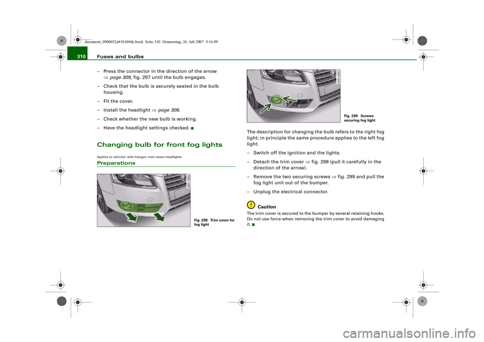
– Detach the trim cover ⇒fig. 298 (pull it carefully in the
direction of the arrow).
– Remove the two securing screws ⇒fig. 299 and pull the
fog light unit out of the bumper.
– Unplug the electrical connector.
CautionThe trim cover is secured to the bumper by several retaining hooks.
Do not use force when removing the trim cover to avoid damaging
it.
Fig. 298 Trim cover for
fog light
Fig. 299 Screws
securing fog light
document_0900452a81b1b9de.book Seite 310 Donnerstag, 26. Juli 2007 9:16 09
Page 314 of 342
Fuses and bulbs 312Applies to vehicles: with halogen main beam headlightsRemoving rear light
To change the bulbs, you must remove the rear light.
Removing the light requires a certain degree of practical
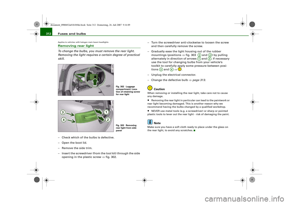
skill.– Check which of the bulbs is defective.
–Open the boot lid.
– Remove the side trim.
– Insert the screwdriver (from the tool kit) through the side
opening in the plastic screw ⇒fig. 302.– Turn the screwdriver anti-clockwise to loosen the screw
and then carefully remove the screw.
– Gradually ease the light housing out of the rubber
mountings (positions ⇒fig. 303 and ) by pulling
alternately in direction of arrows and . If necessary
use the tool for changing bulbs from your vehicle's
toolkit to carefully apply some pressure between posi-
tions and ⇒.
– Unplug the electrical connector.
– Change the defective bulb ⇒page 313.
Caution
When removing or installing the rear light, take care not to cause
any damage.•
Removing the rear light in particular can lead to the paintwork or
rear light becoming damaged. This is another reason why we
recommend having the bulbs changed by a qualified workshop.
•
NEVER use metal tools (e.g. a screwdriver) or sharp or pointed
plastic tools to lever out the rear light - risk of damaging the paint.Note
Make sure you have a soft cloth ready to place under the glass on
the rear light, to avoid any scratches.
Fig. 302 Luggage
compartment: Loca-
tion of retaining screw
for rear lightFig. 303 Removing
rear light from side
panel
A3
A4
A1
A2
A3
A4
document_0900452a81b1b9de.book Seite 312 Donnerstag, 26. Juli 2007 9:16 09
Page 315 of 342
Fuses and bulbs313
Controls
Safety
Driving tips
General maintenance
Self-help
Technical data
Changing bulbs
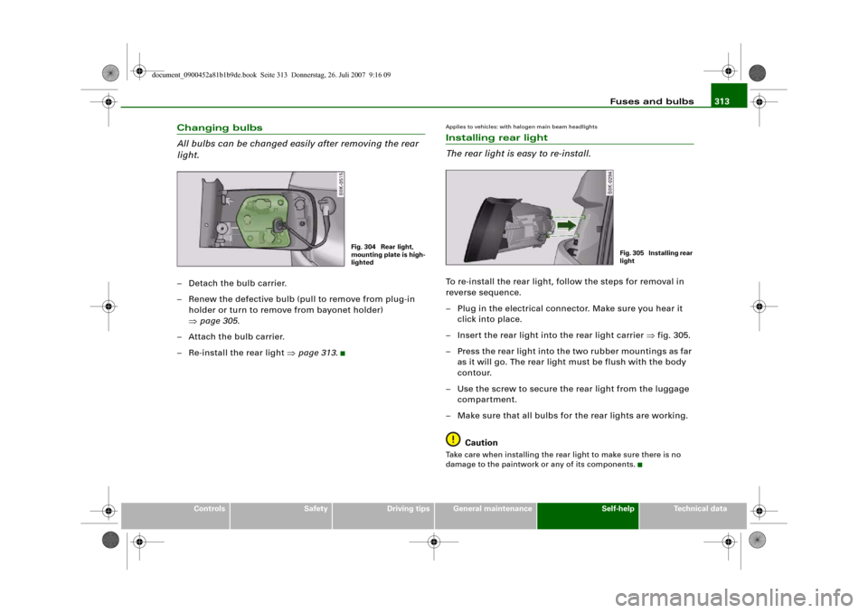
All bulbs can be changed easily after removing the rear
light.– Detach the bulb carrier.
– Renew the defective bulb (pull to remove from plug-in
holder or turn to remove from bayonet holder)
⇒page 305.
– Attach the bulb carrier.
– Re-install the rear light ⇒page 313.
Applies to vehicles: with halogen main beam headlightsInstalling rear light
The rear light is easy to re-install.To re-install the rear light, follow the steps for removal in
reverse sequence.
– Plug in the electrical connector. Make sure you hear it
click into place.
– Insert the rear light into the rear light carrier ⇒fig. 305.
– Press the rear light into the two rubber mountings as far
as it will go. The rear light must be flush with the body
contour.
– Use the screw to secure the rear light from the luggage
compartment.
– Make sure that all bulbs for the rear lights are working.
CautionTake care when installing the rear light to make sure there is no
damage to the paintwork or any of its components.
Fig. 304 Rear light,
mounting plate is high-
lighted
Fig. 305 Installing rear
light
document_0900452a81b1b9de.book Seite 313 Donnerstag, 26. Juli 2007 9:16 09
Page 317 of 342
Fuses and bulbs315
Controls
Safety
Driving tips
General maintenance
Self-help
Technical data
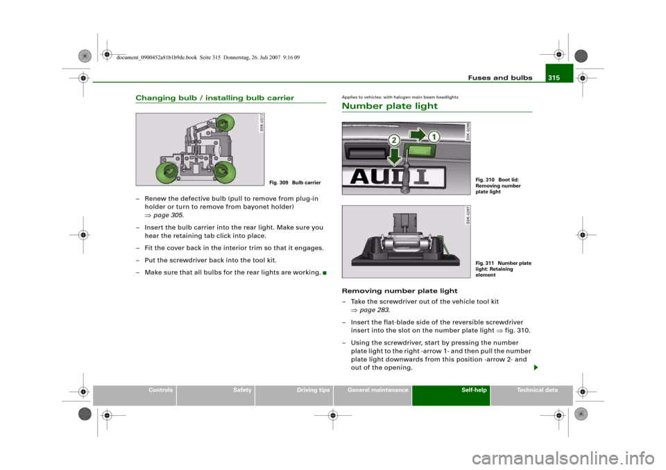
Changing bulb / installing bulb carrier– Renew the defective bulb (pull to remove from plug-in
holder or turn to remove from bayonet holder)
⇒page 305.
– Insert the bulb carrier into the rear light. Make sure you
hear the retaining tab click into place.
– Fit the cover back in the interior trim so that it engages.
– Put the screwdriver back into the tool kit.
– Make sure that all bulbs for the rear lights are working.
Applies to vehicles: with halogen main beam headlightsNumber plate lightRemoving number plate light
– Take the screwdriver out of the vehicle tool kit
⇒page 283.
– Insert the flat-blade side of the reversible screwdriver
insert into the slot on the number plate light ⇒fig. 310.
– Using the screwdriver, start by pressing the number
plate light to the right -arrow 1- and then pull the number
plate light downwards from this position -arrow 2- and
out of the opening.
Fig. 309 Bulb carrier
Fig. 310 Boot lid:
Removing number
plate lightFig. 311 Number plate
light: Retaining
element
document_0900452a81b1b9de.book Seite 315 Donnerstag, 26. Juli 2007 9:16 09
Page 336 of 342
Index 334
Operation . . . . . . . . . . . . . . . . . . . . . . . 121
Parking . . . . . . . . . . . . . . . . . . . . . . . . . 122
Releasing and applying . . . . . . . . . . . 121
Warning lamp . . . . . . . . . . . . . . . . . 19, 20
Electronic differential lock
How the system works . . . . . . . . . . . . 222
Warning lamp . . . . . . . . . . . . . . . . . . . . 19
Electronic immobiliser . . . . . . . . . . . . . 14, 43
Electronic stabilisation program
How the system works . . . . . . . . . . . . 222
Warning lamp . . . . . . . . . . . . . . . . . . . . 17
Emergency braking function . . . . . . . . . . 123
Emergency key . . . . . . . . . . . . . . . . . . . . . . 45
Emergency release
Ignition key . . . . . . . . . . . . . . . . . . . . . . 46
Emission control systems
Catalytic converter . . . . . . . . . . . . . . . 229
Diesel particulate filter . . . . . . . . . . . . 229
Emissions . . . . . . . . . . . . . . . . . . . . . . . . . 321
Engine compartment
Safety notes . . . . . . . . . . . . . . . . . . . . . 255
Engine compartment layout . . . . . . . . . . 256
Engine data
SeePerformance, weights and
dimensions . . . . . . . . . . . . . . . . . . . . 323
Engine hood
SeeBonnet . . . . . . . . . . . . . . . . . . . . . . 254
Engine management
(EPC) warning lamp . . . . . . . . . . . . . . . 16
Engine oil . . . . . . . . . . . . . . . . . . . . . . 34, 257
Checking oil level . . . . . . . . . . . . 258, 259
Consumption . . . . . . . . . . . . . . . . 258, 259
LongLife Service . . . . . . . . . . . . . . . . . 257Topping up . . . . . . . . . . . . . . . . . . . . . . 259
See alsoPerformance, weights and
dimensions . . . . . . . . . . . . . . . . . . . . 323
Engine oil capacity
SeePerformance, weights and
dimensions . . . . . . . . . . . . . . . . . . . . 323
Engine oil pressure
Warning lamp . . . . . . . . . . . . . . . . . . . . 33
Engine oil sensor
Malfunction . . . . . . . . . . . . . . . . . . . . . . 38
Environmental compatibility . . . . . . . . . . 231
Environmental tips
Filling the tank . . . . . . . . . . . . . . . . . . . 252
Heated rear window . . . . . . . . . . . 98, 106
Leaks . . . . . . . . . . . . . . . . . . . . . . . . . . . 255
Roof carrier . . . . . . . . . . . . . . . . . . . . . . 84
EPC
SeeEngine management . . . . . . . . . . . 16
ESP
SeeElectronic stabilisation program . 17
Ethanol fuel . . . . . . . . . . . . . . . . . . . . . . . . 251
Exterior mirrors . . . . . . . . . . . . . . . . . . . . . . 70
FFastening rings . . . . . . . . . . . . . . . . . . 79, 193
Filling the tank . . . . . . . . . . . . . . . . . . . . . 252
Releasing the tank flap manually . . . 253
Fire extinguisher . . . . . . . . . . . . . . . . . . . . 283
First-aid kit . . . . . . . . . . . . . . . . . . . . . . . . . 282
Floor mats . . . . . . . . . . . . . . . . . . . . . 191, 192
Fog lights . . . . . . . . . . . . . . . . . . . . . . . . . . . 58
Four-wheel drive . . . . . . . . . . . . . . . . . . . . 226Front passenger
SeeSitting position . . . . . . . . . . . . . . . 189
Fuel
Biodiesel . . . . . . . . . . . . . . . . . . . . . . . . 251
Capacity . . . . . . . . . . . . . . . . . . . . . . . . 321
Consumption . . . . . . . . . . . . . . . . . . . . 321
Current fuel consumption . . . . . . . . . . 25
Diesel . . . . . . . . . . . . . . . . . . . . . . . . . . 251
Ethanol . . . . . . . . . . . . . . . . . . . . . . . . . 251
Fuel level low . . . . . . . . . . . . . . . . . . . . . 37
Petrol . . . . . . . . . . . . . . . . . . . . . . . . . . 251
Saving fuel . . . . . . . . . . . . . . . . . . . . . . 229
Fuel consumption . . . . . . . . . . . . . . . . . . . 321
Fuel range . . . . . . . . . . . . . . . . . . . . . . . . . . 25
Fuel tank flap . . . . . . . . . . . . . . . . . . . . . . . 252
Fuse, changing . . . . . . . . . . . . . . . . . . . . . 300
GGarage door opener . . . . . . . . . . . . . . . . . 179
Gear-change indicator . . . . . . . . . . . . . . . . 22
Generator
SeeAlternator . . . . . . . . . . . . . . . . . . . . 32
Glove box . . . . . . . . . . . . . . . . . . . . . . . . . . . 90
Glow plug system
Indicator lamp . . . . . . . . . . . . . . . . . . . . 16HHandbrake
SeeElectro-mechanical parking brake . . .
121
document_0900452a81b1b9de.book Seite 334 Donnerstag, 26. Juli 2007 9:16 09
Page 337 of 342
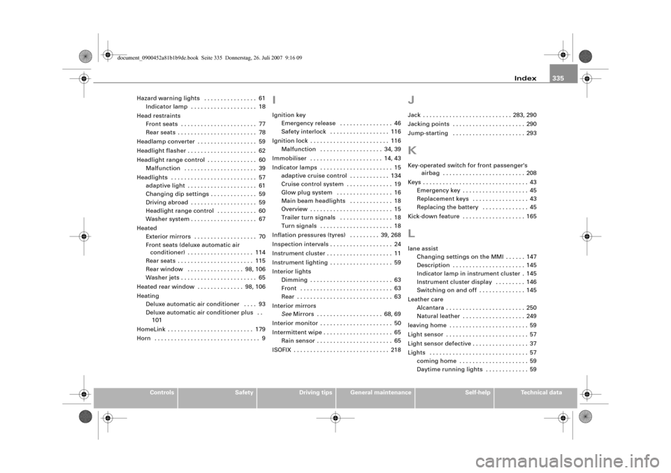
Index335
Controls
Safety
Driving tips
General maintenance
Self-help
Technical data Hazard warning lights . . . . . . . . . . . . . . . . 61
Indicator lamp . . . . . . . . . . . . . . . . . . . . 18
Head restraints
Front seats . . . . . . . . . . . . . . . . . . . . . . . 77
Rear seats . . . . . . . . . . . . . . . . . . . . . . . . 78
Headlamp converter . . . . . . . . . . . . . . . . . . 59
Headlight flasher . . . . . . . . . . . . . . . . . . . . . 62
Headlight range control . . . . . . . . . . . . . . . 60
Malfunction . . . . . . . . . . . . . . . . . . . . . . 39
Headlights . . . . . . . . . . . . . . . . . . . . . . . . . . 57
adaptive light . . . . . . . . . . . . . . . . . . . . . 61
Changing dip settings . . . . . . . . . . . . . . 59
Driving abroad . . . . . . . . . . . . . . . . . . . . 59
Headlight range control . . . . . . . . . . . . 60
Washer system . . . . . . . . . . . . . . . . . . . . 67
Heated
Exterior mirrors . . . . . . . . . . . . . . . . . . . 70
Front seats (deluxe automatic air
conditioner) . . . . . . . . . . . . . . . . . . . . 114
Rear seats . . . . . . . . . . . . . . . . . . . . . . . 115
Rear window . . . . . . . . . . . . . . . . . 98, 106
Washer jets . . . . . . . . . . . . . . . . . . . . . . . 65
Heated rear window . . . . . . . . . . . . . . 98, 106
Heating
Deluxe automatic air conditioner . . . . 93
Deluxe automatic air conditioner plus . .
101
HomeLink . . . . . . . . . . . . . . . . . . . . . . . . . . 179
Horn . . . . . . . . . . . . . . . . . . . . . . . . . . . . . . . . 9
IIgnition key
Emergency release . . . . . . . . . . . . . . . . 46
Safety interlock . . . . . . . . . . . . . . . . . . 116
Ignition lock . . . . . . . . . . . . . . . . . . . . . . . . 116
Malfunction . . . . . . . . . . . . . . . . . . . 34, 39
Immobiliser . . . . . . . . . . . . . . . . . . . . . . 14, 43
Indicator lamps . . . . . . . . . . . . . . . . . . . . . . 15
adaptive cruise control . . . . . . . . . . . . 134
Cruise control system . . . . . . . . . . . . . . 19
Glow plug system . . . . . . . . . . . . . . . . . 16
Main beam headlights . . . . . . . . . . . . . 18
Overview . . . . . . . . . . . . . . . . . . . . . . . . . 15
Trailer turn signals . . . . . . . . . . . . . . . . 18
Turn signals . . . . . . . . . . . . . . . . . . . . . . 18
Inflation pressures (tyres) . . . . . . . . . 39, 268
Inspection intervals . . . . . . . . . . . . . . . . . . . 24
Instrument cluster . . . . . . . . . . . . . . . . . . . . 11
Instrument lighting . . . . . . . . . . . . . . . . . . . 59
Interior lights
Dimming . . . . . . . . . . . . . . . . . . . . . . . . . 63
Front . . . . . . . . . . . . . . . . . . . . . . . . . . . . 63
Rear . . . . . . . . . . . . . . . . . . . . . . . . . . . . . 63
Interior mirrors
SeeMirrors . . . . . . . . . . . . . . . . . . . . 68, 69
Interior monitor . . . . . . . . . . . . . . . . . . . . . . 50
Intermittent wipe . . . . . . . . . . . . . . . . . . . . . 65
Rain sensor . . . . . . . . . . . . . . . . . . . . . . . 65
ISOFIX . . . . . . . . . . . . . . . . . . . . . . . . . . . . . 218
JJack . . . . . . . . . . . . . . . . . . . . . . . . . . . 283, 290
Jacking points . . . . . . . . . . . . . . . . . . . . . . 290
Jump-starting . . . . . . . . . . . . . . . . . . . . . . 293KKey-operated switch for front passenger's
airbag . . . . . . . . . . . . . . . . . . . . . . . . . 208
Keys . . . . . . . . . . . . . . . . . . . . . . . . . . . . . . . . 43
Emergency key . . . . . . . . . . . . . . . . . . . . 45
Replacement keys . . . . . . . . . . . . . . . . . 43
Replacing the battery . . . . . . . . . . . . . . 45
Kick-down feature . . . . . . . . . . . . . . . . . . . 165Llane assist
Changing settings on the MMI . . . . . . 147
Description . . . . . . . . . . . . . . . . . . . . . . 145
Indicator lamp in instrument cluster . 145
Instrument cluster display . . . . . . . . . 146
Switching on and off . . . . . . . . . . . . . . 145
Leather care
Alcantara . . . . . . . . . . . . . . . . . . . . . . . . 250
Natural leather . . . . . . . . . . . . . . . . . . . 249
leaving home . . . . . . . . . . . . . . . . . . . . . . . . 59
Light sensor . . . . . . . . . . . . . . . . . . . . . . . . . 57
Light sensor defective . . . . . . . . . . . . . . . . . 37
Lights . . . . . . . . . . . . . . . . . . . . . . . . . . . . . . 57
coming home . . . . . . . . . . . . . . . . . . . . . 59
Daytime running lights . . . . . . . . . . . . . 59
document_0900452a81b1b9de.book Seite 335 Donnerstag, 26. Juli 2007 9:16 09