tow AUDI A4 2008 B8 / 4.G User Guide
[x] Cancel search | Manufacturer: AUDI, Model Year: 2008, Model line: A4, Model: AUDI A4 2008 B8 / 4.GPages: 342, PDF Size: 13.14 MB
Page 60 of 342
Lights and vision 58
WARNING
The automatic headlights are only intended to assist the driver.
The driver must always ensure that the headlights are used when
required, and may have to switch the m o n m a n u a l l y when the light
conditions or visibility are poor. For example, the light sensors are
not able to detect fog. Therefore, you should always switch on the
headlights
in these conditions and when driving after dark.
Note
•
The light sensor for automatic headlight control is located in the
mounting for the interior mirror. Do not affix any stickers on this
section of the windscreen to avoid malfunctioning of the sensor.
•
Some of the settings for the exterior lighting can be adjusted
⇒page 59.
•
If the lights are left on after the key has been taken out of the
ignition lock, a buzzer sounds when the driver's door is opened.
•
The use of the lighting described here is subject to the relevant
statutory requirements.
•
The coming home/leaving home function is active only when the
light switch is set to AUTO.
Fog lights
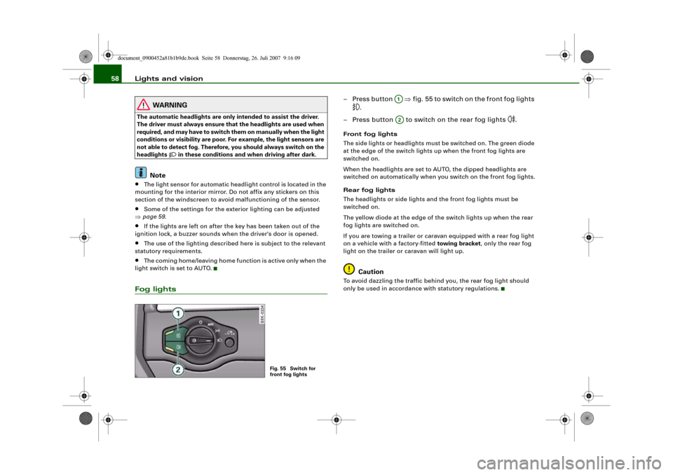
– Press button ⇒fig. 55 to switch on the front fog lights
.
– Press button to switch on the rear fog lights
.
Front fog lights
The side lights or headlights must be switched on. The green diode
at the edge of the switch lights up when the front fog lights are
switched on.
When the headlights are set to AUTO, the dipped headlights are
switched on automatically when you switch on the front fog lights.
Rear fog lights
The headlights or side lights and the front fog lights must be
switched on.
The yellow diode at the edge of the switch lights up when the rear
fog lights are switched on.
If you are towing a trailer or caravan equipped with a rear fog light
on a vehicle with a factory-fitted towing bracket, only the rear fog
light on the trailer or caravan will light up.
Caution
To avoid dazzling the traffic behind you, the rear fog light should
only be used in accordance with statutory regulations.
Fig. 55 Switch for
front fog lights
A1A2
document_0900452a81b1b9de.book Seite 58 Donnerstag, 26. Juli 2007 9:16 09
Page 64 of 342
Lights and vision 62•
When reaching the tail end of a traffic jam
•
If your vehicle breaks down or there is an emergency
•
If your vehicle is being towed away, or if you are towing another
vehicle.
Turn signal and main beam lever
The turn signal and main beam lever also operates the
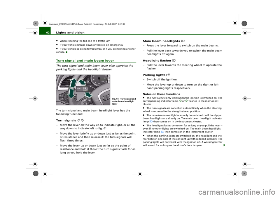
parking lights and the headlight flasher.The turn signal and main beam headlight lever has the
following functions:
Turn signals
– Move the lever all the way up to indicate right, or all the
way down to indicate left ⇒fig. 61.
– Move the lever briefly up or down just as far as the point
of resistance and then release it: the turn signals will
flash three times.
– Move the lever up or down just as far as the point of
resistance and hold it there: the turn signals flash for as
long as you hold the lever.Main beam headlights
– Press the lever forward to switch on the main beams.
– Pull the lever back towards you to switch the main beam
headlights off again.
Headlight flasher
– Pull the lever towards the steering wheel to operate the
flasher.
Parking lights
– Switch off the ignition.
– Move the lever up or down to turn on the right or left-
hand parking lights respectively.Notes on these functions•
The turn signals only work when the ignition is switched on. The
corresponding indicator lamp
or
flashes in the instrument
cluster.
•
The turn signals are cancelled automatically when the steering
wheel is returned to the straight-ahead position.
•
The main beam headlights can only be switched on if the dipped
beam headlights are already on. The main beam headlight indicator
lamp then comes on in the instrument cluster.
•
The headlight flasher comes on for as long as you pull the lever –
even if no other lights are switched on. The main beam headlight
indicator lamp
then comes on in the instrument cluster.
•
When the parking lights are switched on, the headlight and the
rear light on one side of the car light up with reduced intensity. The
parking lights will only work with the ignition off. A warning buzzer
will sound for as long as the driver's door is open.
Fig. 61 Turn signal and
main beam headlight
lever
document_0900452a81b1b9de.book Seite 62 Donnerstag, 26. Juli 2007 9:16 09
Page 66 of 342
Lights and vision 64Clear visionSun visors
The sun visors can improve visibility and contribute to
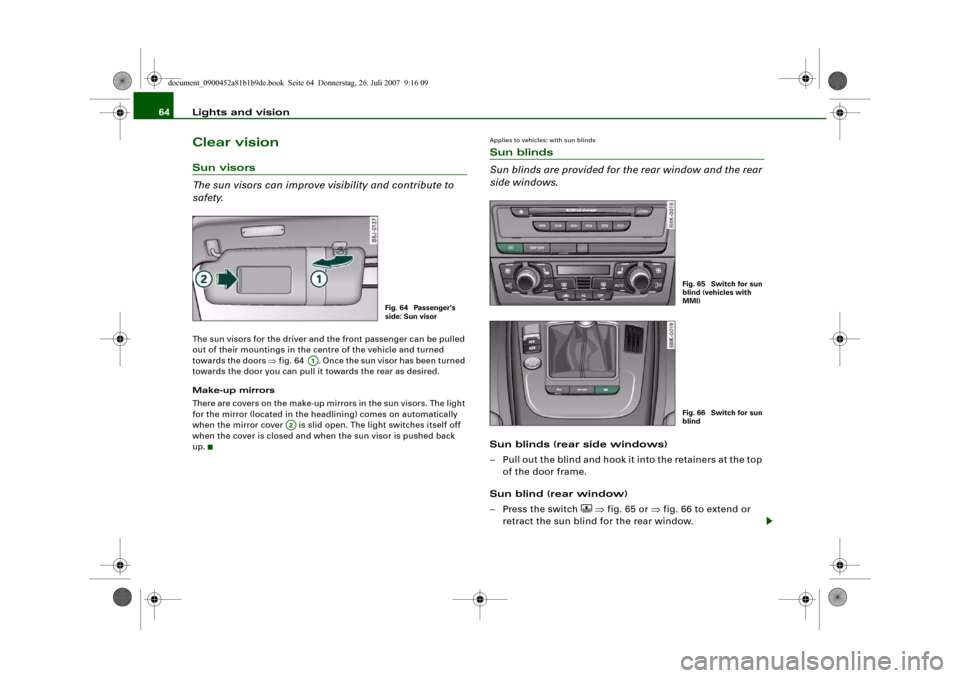
safety.The sun visors for the driver and the front passenger can be pulled
out of their mountings in the centre of the vehicle and turned
towards the doors ⇒fig. 64 . Once the sun visor has been turned
towards the door you can pull it towards the rear as desired.
Make-up mirrors
There are covers on the make-up mirrors in the sun visors. The light
for the mirror (located in the headlining) comes on automatically
when the mirror cover is slid open. The light switches itself off
when the cover is closed and when the sun visor is pushed back
up.
Applies to vehicles: with sun blindsSun blinds
Sun blinds are provided for the rear window and the rear
side windows.Sun blinds (rear side windows)
– Pull out the blind and hook it into the retainers at the top
of the door frame.
Sun blind (rear window)
– Press the switch
⇒fig. 65 or ⇒fig. 66 to extend or
retract the sun blind for the rear window.
Fig. 64 Passenger's
side: Sun visor
A1
A2
Fig. 65 Switch for sun
blind (vehicles with
MMI)Fig. 66 Switch for sun
blind
document_0900452a81b1b9de.book Seite 64 Donnerstag, 26. Juli 2007 9:16 09
Page 71 of 342
Lights and vision69
Controls
Safety
Driving tips
General maintenance
Self-help
Technical data
Anti-dazzle setting
– Pull the lever at the bottom of the mirror towards you.Applies to vehicles: with automatic anti-dazzle adjustment for interior mirrorAutomatic anti-dazzle adjustment
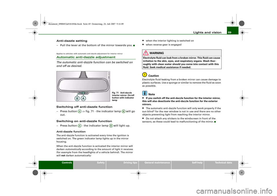
The automatic anti-dazzle function can be switched on
and off as desired.Switching off anti-dazzle function
– Press button ⇒fig. 71 - the indicator lamp will go
out.
Switching on anti-dazzle function
– Press button - the indicator lamp will light up.Anti-dazzle function
The anti-dazzle function is activated every time the ignition is
switched on. The green indicator lamp lights up in the mirror
housing.
When the anti-dazzle function is activated the interior mirror will
darken automatically according to the amount of light it receives
(for example from the headlights of a vehicle behind). The mirror
will not darken automatically:
•
when the interior lighting is switched on
•
when reverse gear is engaged
WARNING
Electrolyte fluid can leak from a broken mirror. This fluid can cause
irritation to the skin, eyes, and respiratory organs. Wash thor-
oughly with clean water should you come into contact with this
fluid. Seek medical assistance if needed.
Caution
Electrolyte fluid leaking from a broken mirror can cause damage to
plastic surfaces. Use a sponge or similar to remove the fluid as soon
as possible.
Note
•
If you switch off the anti-dazzle function for the interior mirror,
this will also deactivate the anti-dazzle function for the exterior
mirrors.
•
The automatic anti-dazzle function will only work properly if the
sun blind* for the rear window is not in use and there are no other
objects preventing light from reaching the interior mirror.
•
Do not attach any stickers to the windscreen in front of the
sensors, as these could lead to malfunctioning of the mirror.
Fig. 71 Anti-dazzle
interior mirror: On/off
button with indicator
lamp
AA
AB
AA
AB
document_0900452a81b1b9de.book Seite 69 Donnerstag, 26. Juli 2007 9:16 09
Page 85 of 342
Seats and storage83
Controls
Safety
Driving tips
General maintenance
Self-help
Technical data
– Open the boot lid.
– Open out the ski bag and fill it with the items you wish to
transport.
– Push the ski bag from the luggage compartment into the
passenger compartment through the opening in the
backrest ⇒.
Securing
– Insert the fastening belt ⇒page 82, fig. 91 of the ski
bag into the centre seat belt buckle .
– Pull the free end of belt to tighten.
Storage
– Pull the ski bag towards the rear through the opening in
the backrest.
– Close the cover of the load-through hatch in the
passenger compartment.
–Fold up the ski bag.
WARNING
The ski bag must be secured in place with the fastening belt after
it has been loaded.
Note
Allow the ski bag to dry before folding it up.
Roof carrierApplies to vehicles: with roof carrier: Under development at the time of printDescription
Additional loads can be transported using the roof carrier.Note the following points if you intend to carry loads on the roof:•
The rain channels are moulded into the roof as part of the aero-
dynamic roof design. It is therefore not possible to mount conven-
tional roof luggage racks. We recommend using the carrier units
from the range of Audi Genuine accessories.
•
These carrier units form the basic elements of a complete roof
carrier system. Special fixtures must then be added in order to
safely transport luggage, bicycles, skis, surf boards or boats on the
roof. All the elements of this system are available from Audi dealers.Caution
Any damage to the vehicle caused by the use of other types of roof
rack or incorrect installation will not be covered by the factory
warranty. The roof carrier system must therefore be installed exactly
according to the instructions provided.
AA
AB
AC
document_0900452a81b1b9de.book Seite 83 Donnerstag, 26. Juli 2007 9:16 09
Page 91 of 342
Seats and storage89
Controls
Safety
Driving tips
General maintenance
Self-help
Technical data
Applies to vehicles: with 230 Volt Euro socketOn-board 230 Volt Euro socketElectrical equipment can be connected to the 230 Volt
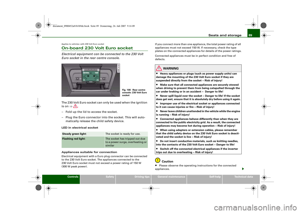
Euro socket in the rear centre console.The 230 Volt Euro socket can only be used when the ignition
is on ⇒.
– Fold up the lid to access the socket.
– Plug the Euro connector into the socket. This will auto-
matically release the child safety device.LED in electrical socket
Appliances suitable for connection
Electrical equipment with a Euro plug connector can be connected
to the 230 Volt Euro socket. The appliances connected to the
230 Volt Euro socket must not exceed a power rating of 150 W
(300 W peak power).If you connect more than one appliance, the total power rating of all
appliances must not exceed 150 W. If necessary, check the type
plates on the connected appliances for details of the power ratings.
Connected appliances must be in perfect condition and free of
defects.
WARNING
•
Heavy appliances or plugs (such as power supply units) can
damage the mounting of the 230 Volt Euro socket if they are
suspended directly from the socket – Risk of injury!
•
Make sure that all connected appliances are securely stowed
when driving to prevent them from being catapulted through the
car under braking or in an accident – Danger to life!
•
Never spill liquid over the socket – Danger to life! If the socket
does get wet, ensure that it is absolutely dry before using it again.
•
Improper use of the electrical socket or appliances connected
to it can cause injuries or fire – Risk of injury!
•
Never leave children unattended in the vehicle while the engine
is running – Risk of injury!
•
Connected appliances behave differently than when they are
connected to the public electricity grid. As a result, the connected
appliances may become hot during operation – Risk of injury!
•
When using adapters or extension cables, please remember
that the child safety device on the 230 Volt Euro socket is deacti-
vated and the socket is live – Risk of injury!
•
Do not insert conductive materials, such as knitting needles,
into the contacts of the 230 Volt Euro socket – Danger to life!
•
Switch off the connected electrical appliances if the inverter
trips out due to overheating – Risk of injury!Caution
•
Please observe the operating instructions for the connected
appliances.
Steady green light:
The socket is ready for use.
Flashing red light:
The socket has tripped out due
to a power surge, overheating or
similar
Fig. 100 Rear centre
console: 230 Volt Euro
socket
document_0900452a81b1b9de.book Seite 89 Donnerstag, 26. Juli 2007 9:16 09
Page 118 of 342
Driving 116DrivingSteeringApplies to vehicles: with manually adjustable steering columnAdjusting the steering wheel position
The height and reach of the steering wheel can be
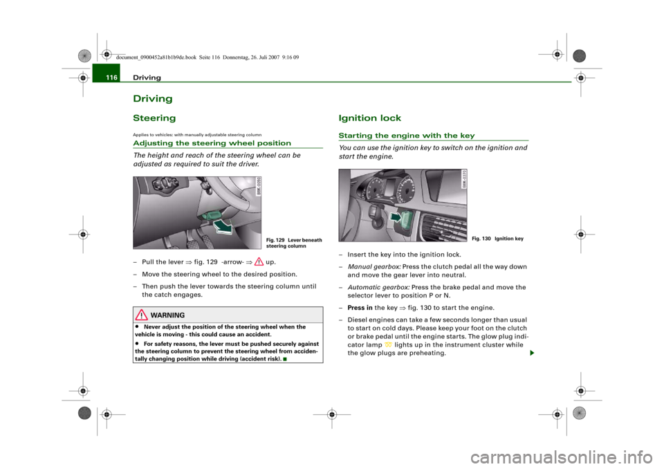
adjusted as required to suit the driver.– Pull the lever ⇒fig. 129 -arrow- ⇒ up.
– Move the steering wheel to the desired position.
– Then push the lever towards the steering column until
the catch engages.
WARNING
•
Never adjust the position of the steering wheel when the
vehicle is moving - this could cause an accident.
•
For safety reasons, the lever must be pushed securely against
the steering column to prevent the steering wheel from acciden-
tally changing position while driving (accident risk).
Ignition lockStarting the engine with the key
You can use the ignition key to switch on the ignition and
start the engine.– Insert the key into the ignition lock.
–Manual gearbox: Press the clutch pedal all the way down
and move the gear lever into neutral.
–Automatic gearbox: Press the brake pedal and move the
selector lever to position P or N.
–Press in the key ⇒fig. 130 to start the engine.
– Diesel engines can take a few seconds longer than usual
to star t on cold days. Please keep your foot on the clutch
or brake pedal until the engine starts. The glow plug indi-
cator lamp
lights up in the instrument cluster while
the glow plugs are preheating.
Fig. 129 Lever beneath
steering column
Fig. 130 Ignition key
document_0900452a81b1b9de.book Seite 116 Donnerstag, 26. Juli 2007 9:16 09
Page 122 of 342
Driving 120Steering lock
The steering is locked if the key is not in the ignition and the driver
door has been opened. The steering lock acts as a theft deterrent.
WARNING
Never run the engine in confined spaces. The exhaust gases are
toxic.•
Never switch off the engine until the vehicle is stationary.
•
The brake servo and the power steering system work only
when the engine is running. You need more strength to steer and
brake the vehicle when the engine is switched off. This would
mean a greater risk of accidents and serious injury, because you
cannot steer and brake in the normal manner.Caution
•
Avoid high engine speeds, full throttle and extreme load condi-
tions until the engine has reached its normal operating tempera-
ture, otherwise this can damage the engine.
•
The engine cannot be started by push-starting or towing.
•
If the engine has been working hard for a long time, there is a risk
of heat building up in the engine compartment after the engine has
been switched off; this could cause engine damage. For this reason,
you should leave the engine idling for about 2 minutes before
switching it off.Note
If you open the driver's door while the ignition is switched on, a
warning buzzer will sound, and the message Ignition is on will
appear in the display. In this case, please switch off the ignition.
Switching off the engine with the Start/Stop button–Stop the vehicle.
– Automatic gearbox: Move the selector lever to position P
or N.
–Press the Start/Stop button ⇒page 118, fig. 131.Emergency Off function
Should it be necessary in an emergency, the engine can be switched
off when the selector lever is in position R, D or S. To switch off the
engine (max. speed 10 km/h) press and hold the Start/Stop button
and keep your foot on the brake.
WARNING
•
Never switch off the engine until the vehicle is stationary.
•
The brake servo and the power steering system work only
when the engine is running. You need more strength to steer and
brake the vehicle when the engine is switched off. This would
mean a greater risk of accidents and serious injury, because you
cannot steer and brake in the normal manner.Caution
If the engine has been working hard for a long time, there is a risk
of heat building up in the engine compartment after the engine has
been switched off; this could cause engine damage. For this reason,
you should leave the engine idling for about 2 minutes before
switching it off.
Note
After the engine is stopped the radiator fan may run on for up to
10 minutes, even if the ignition is switched off. The fan may also
document_0900452a81b1b9de.book Seite 120 Donnerstag, 26. Juli 2007 9:16 09
Page 125 of 342
Driving123
Controls
Safety
Driving tips
General maintenance
Self-help
Technical data braking force of the parking brake is only released when there is
enough power at the wheels to make the vehicle move in the desired
direction.
Note
For safety reasons the parking brake will only release automatically
if the driver's seat belt is engaged in its buckle.Driving away when towing a trailer
Please note the following points to prevent the vehicle
from rolling back unintentionally on a gradient.– Pull and hold the parking brake switch and press the
accelerator. The parking brake will remain engaged and
prevent any tendency to roll back down the slope.
– You can release the parking brake switch as soon as the
engine is delivering enough power to the wheels.Depending on the weight of the vehicle and trailer and the steep-
ness of the slope, there may be a tendency to roll back downhill
when driving away from a standstill. You can prevent this by pulling
out the parking brake switch as you press the accelerator (in the
same way as with a conventional handbrake).Emergency braking function
This feature enables you to stop the vehicle if the main
brake system should fail or if the pedal is obstructed.– Pull out and hold the parking brake switch to stop the
vehicle with the parking brake in an emergency.
– The brakes will be released immediately if you release the
switch or press down the accelerator.
If you pull out and hold the parking brake switch at a road speed
above about 8 km/h, this will initiate an emergency brake applica-
tion. The brakes are then applied hydraulically at all four wheels.
The effect is the same as an emergency stop (full brake application)
⇒
To prevent the emergency braking function from being used acci-
dentally, a warning buzzer sounds when the switch is operated. The
brakes are released immediately when you release the switch or
press down the accelerator.
WARNING
You should only use the emergency braking function in a real
emergency, for example if the brake system should fail or if the
brake pedal is obstructed. If you use the emergency braking func-
tion by activating the parking brake switch, the effect is similar to
a full brake application (emergency stop). Please remember that
the ESP (with its combined ABS, EDL and traction control func-
tions) is still subject to certain physical limits. In a corner or in bad
road or weather conditions an emergency stop can cause the
vehicle to skid or lose steering control.Driver messages in the instrument cluster displayCaution: Vehicle parked too steep
This message can appear when you apply the parking brake if the
car is parked on a gradient steeper than about 30%.
In this case the parking brake may not be strong enough to prevent
the vehicle from rolling back accidentally.
Please release parking brake
However, please remember that, for safety reasons, the parking
brake will only release automatically if the driver's seat belt is
buckled.
document_0900452a81b1b9de.book Seite 123 Donnerstag, 26. Juli 2007 9:16 09
Page 128 of 342
Driving 126
– Pull the lever to position ⇒page 125, fig. 134 to
switch on the system.
– Drive at the speed you wish to set the system to.
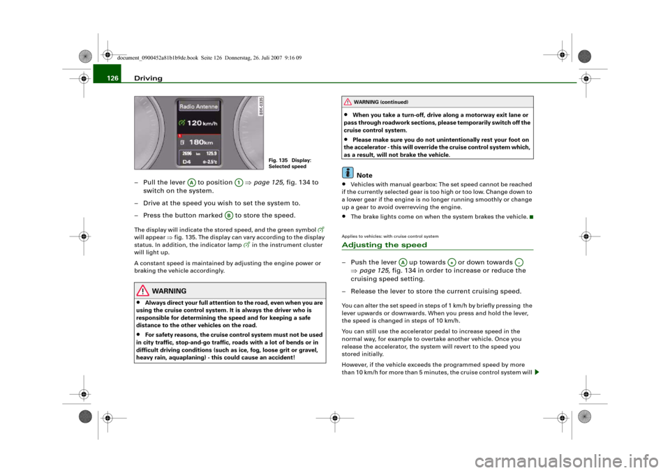
– Press the button marked to store the speed.The display will indicate the stored speed, and the green symbol
will appear ⇒fig. 135. The display can vary according to the display
status. In addition, the indicator lamp
in the instrument cluster
will light up.
A constant speed is maintained by adjusting the engine power or
braking the vehicle accordingly.
WARNING
•
Always direct your full attention to the road, even when you are
using the cruise control system. It is always the driver who is
responsible for determining the speed and for keeping a safe
distance to the other vehicles on the road.
•
For safety reasons, the cruise control system must not be used
in city traffic, stop-and-go traffic, roads with a lot of bends or in
difficult driving conditions (such as ice, fog, loose grit or gravel,
heavy rain, aquaplaning) - this could cause an accident!
•
When you take a turn-off, drive along a motorway exit lane or
pass through roadwork sections, please temporarily switch off the
cruise control system.
•
Please make sure you do not unintentionally rest your foot on
the accelerator - this will override the cruise control system which,
as a result, will not brake the vehicle.Note
•
Vehicles with manual gearbox: The set speed cannot be reached
if the currently selected gear is too high or too low. Change down to
a lower gear if the engine is no longer running smoothly or change
up a gear to avoid overrevving the engine.
•
The brake lights come on when the system brakes the vehicle.
Applies to vehicles: with cruise control systemAdjusting the speed– Push the lever up towards or down towards
⇒page 125, fig. 134 in order to increase or reduce the
cruising speed setting.
– Release the lever to store the current cruising speed.You can alter the set speed in steps of 1 km/h by briefly pressing the
lever upwards or downwards. When you press and hold the lever,
the speed is changed in steps of 10 km/h.
You can still use the accelerator pedal to increase speed in the
normal way, for example to overtake another vehicle. Once you
release the accelerator, the system will revert to the speed you
stored initially.
However, if the vehicle exceeds the programmed speed by more
than 10 km/h for more than 5 minutes, the cruise control system will
Fig. 135 Display:
Selected speed
AA
A1
AB
WARNING (continued)
AA
A+
A-
document_0900452a81b1b9de.book Seite 126 Donnerstag, 26. Juli 2007 9:16 09