light AUDI A4 2020 Owners Manual
[x] Cancel search | Manufacturer: AUDI, Model Year: 2020, Model line: A4, Model: AUDI A4 2020Pages: 296, PDF Size: 80.45 MB
Page 259 of 296

8W1012721BB
Emergency assistance
bracket on the jack @) completely covers the
notch on the vehicle.
> Align the vehicle jack so the bracket (@ covers
the notch and the base (2) is flat on the ground.
The base @) must be directly under the mount-
ing point @.
> Mount the crank on the vehicle jack: insert the
crank into the opening on the handwheel. Turn
the crank to the left or right to secure it.
> Continue raising the vehicle jack with the crank
until the wheel lifts off the ground slightly.
ZA WARNING
—To reduce the risk of injury, make sure no
one is in the vehicle before raising it.
— Make sure the vehicle jack is stable. The risk
of injury is increased when the ground is
slippery or soft, because the vehicle jack
could slide or sink.
— Only raise your vehicle with the vehicle jack
provided by the factory. If you use a vehicle
jack designed for another vehicle, your vehi-
cle could slip and cause injury.
— Position the vehicle jack only at the desig-
nated mounting points on the side sill and
align the jack. Otherwise, the vehicle jack
could slip and cause an injury if it does not
have sufficient hold on the vehicle.
—To reduce the risk of injury, do not raise any
other vehicles or other loads using the vehi-
cle jack provided by the factory.
— To reduce the risk of an accident, never start
the
engine when the vehicle is raised.
—To reduce the risk of injury, no work should
be performed under the vehicle while it is
raised.
@) Note
Do not lift the vehicle by the sill. Position the
vehicle jack only at the designated mounting
points on the side sill. Otherwise, your vehicle
could be damaged.
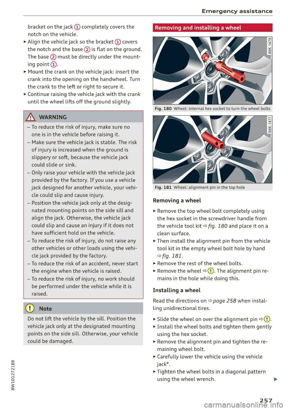
Removing and installing a wheel
2 Rg + ~
oO oO
B8K-1477
Fig. 181 Wheel: alignment pin in the top hole
Removing a wheel
> Remove the top wheel bolt completely using
the hex socket in the screwdriver handle from
the vehicle tool kit > fig. 180 and place it ona
clean surface.
> Then install the alignment pin from the vehicle
tool kit in the empty wheel bolt hole by hand
> fig. 181.
> Remove the rest of the wheel bolts.
>» Remove the wheel >(). The alignment pin re-
mains in the hole while doing this.
Installing a wheel
Read the directions on > page 258 when instal-
ling unidirectional tires.
> Slide the wheel on over the alignment pin >@.
> Install the wheel bolts and tighten them gently
using the hex socket.
> Remove the alignment pin and tighten the re-
maining wheel bolt.
> Carefully lower the vehicle using the vehicle
jack*.
> Tighten the wheel bolts in a diagonal pattern
using the wheel wrench.
257
Page 263 of 296

8W1012721BB
Emergency assistance
1. Attach one end of the positive cable (red) to
the jump-start pin @ > fig. 183 on your vehi-
cle.
2. Attach the other end of the positive cable
(red) to the positive terminal @ on the pow-
er source.
Connecting the negative cable (black) to the
negative terminal
3. Attach one end of the negative cable (black)
to the negative terminal @) on the power
source.
4. Attach the other end of the negative cable
(black) to the negative terminal @) on the ve-
hicle.
Starting the engine
> Start the engine in the vehicle giving the charge
and let it run at idle.
> Now start the engine in your vehicle, which has
the
drained battery.
> If the engine does not start, stop the starting
procedure after 10 seconds and then repeat it
after approximately 30 seconds.
> Turn on the rear window defogger in your vehi-
cle in order to reduce any voltage peaks that
may occur when disconnecting the jump start
cables. The headlights must be switched off.
> With the engines running, remove the cables in
reverse order of the way they were installed.
> Close the red cover on the positive terminal.
ZA WARNING
— Never connect the jump start cable directly
to your vehicle battery. Only use the connec-
tions in the engine compartment.
— Do not touch the non-insulated parts of the
terminal clamps. The cable must also not
come into contact with vehicle components
that conduct electricity when it is connected
to the positive vehicle battery terminal. This
can cause a short circuit.
— The plugs on the battery cells must not be
opened.
— Keep ignition sources (such as open flames,
burning cigarettes, etc.) away from the vehi-
cle batteries to reduce the risk of an explo-
sion.
— Route the jump start cables so they cannot
get caught in the moving parts in the other
vehicle's engine compartment.
Q) Note
Please note that the connecting process previ-
ously described for the jump start cables is in-
tended for when your vehicle is being jump
started.
@) Tips
Make sure that the connected jump start ca-
bles have sufficient contact with metal.
Towing
General information
You should only perform the steps that follow if
you have the necessary tools and technical ex-
pertise.
Towing requires a certain amount of practice.
Audi recommends contacting a towing company
to have the vehicle transported.
You should only have your vehicle towed by an-
other vehicle when disabled in exceptional cir-
cumstances. Inexperienced drivers should not
tow.
Notes on towing
When the engine is stopped, the transmission
will not be sufficiently lubricated if traveling at
high speeds and long distances:
— The maximum permitted towing speed is 30
mph (50 km/h).
— The maximum permitted towing distance is 30
miles (50 km).
Additional information on towing with a tow
truck
The vehicle may only be towed with the front axle
raised. Do not wrap any chains or cables around
the brake lines.
Tow bar and towing cable
The vehicle can be towed with a tow bar or tow-
ing cable. Both drivers should be familiar with
261
>
Page 266 of 296

Fuses and bulbs
Fig. 185 Driver's side footwell (left-hand drive vehicles):
footrest (@), front passenger's footwell (right-hand drive
vehicles): cover @)
5 g
=
=
8
=
Fig. 186 Driver's side cockpit (left-hand drive/right-hand
drive vehicles): cover ©, left side of luggage compartment:
cover ()
264
A fuse that has blown will have metal strips that
have burned through.
The fuses are located in the footwell under the
foot rest (left-hand drive vehicle) @
the cover (right-hand drive vehicle) (8). Additional
fuses are located on the front side of the cockpit
(driver's side) © and under the left cover in the
luggage compartment (
> Switch the ignition and all electrical equipment
off.
> Check the table that follows to see which fuse
belongs to the equipment.
> Remove the screwdriver and the reversible Torx
bit from the vehicle tool kit > page 253.
> Remove the footrest or the corresponding cov-
er.
> Remove the colored plastic clip from the fuse
panel, if necessary > page 265, fig. 187.
> Remove the clip from the rear side of the cover
» Remove the fuse using the clip.
> Replace the blown fuse only with a fuse that
has the same amp rating.
> Reinstall the plastic bracket.
> Reattach the footrest or the cover.
Fuse color identification
Color Current rating
in amps
Black 1
Purple 3
Light brown 5
Brown Z.9
Red 10
Blue 1S
Yellow 20
White or transparent [25
Green 30
Orange 40
Z\ WARNING
Do not repair fuses and never replace a blown
fuse with one that has a higher amp rating.
This can cause damage to the electrical sys-
tem and increases the risk of fire.
Page 267 of 296

8W1012721BB
Fuses and bulbs
@) Note
If a new fuse burns out again shortly after you
have installed it, have the electrical system
checked as soon as possible by an authorized
Audi dealer or authorized Audi Service Facili-
it y.
G@) Tips
— The following table does not list fuse loca-
tions that are not used.
— Some of the equipment listed in the follow-
ing tables applies only to certain model ver-
sions or certain optional equipment.
Fig. 187 Driver's footwell (left-hand drive vehicle): fuse
panel with plastic clip
3
=f
= & a
x
Ss $ 2 8
Fig. 188 Front passenger's footwell (right-hand drive vehi-
cle): fuse panel with plastic clip
) (brown)
No. | Equipment
2 |Engine components
Exhaust doors, fuel injectors, radiator in-
let, crankcase housing heating
Vacuum pump, hot water pump, NOx sen-
4 |sor, particulate sensor, biodiesel sensor,
exhaust doors
Brake light sensor
6 | Engine valves, camshaft adjustment
Heated oxygen sensors, mass airflow sen-
sor, water pump
Water pump, high pressure pump, high
8 |pressure regulator valve, temperature
valve, engine mount
9 |Hot water pump, engine relay
10 | Oil pressure sensor, oil temperature sensor
Clutch pedal position sensor, engine start,
water pump
i
12 | Engine valves, engine mount
13 | Radiator fan
14 | Fuel injectors, engine control module
265
Page 268 of 296

Fuses and bulbs
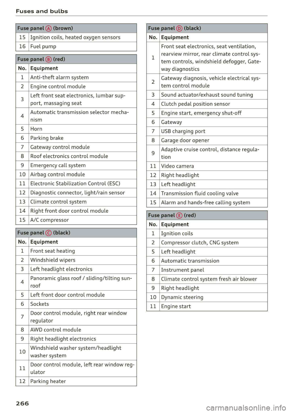
Fuse panel @) (brown) Fuse panel (0) (black)
15 |Ignition coils, heated oxygen sensors No. | Equipment
16 | Fuel pump Front seat electronics, seat ventilation,
= rearview mirror, rear climate control sys-
Fuse panel @) (red) | era controls, windshield defogger, Gate-
No. | Equipment way diagnostics
Anti-theft alarm system 2 Gateway diagnosis, vehicle electrical sys-
2 |Engine control module tem control module
3 [Left front seat electronics, lumbar sup- 3 | Sound actuator/exhaust sound tuning
port, massaging seat 4 |Clutch pedal position sensor
4 Automatic transmission selector mecha- 5 | Engine start, emergency shut-off
Sct 6 | Gateway
5 [Horn 7 |USB charging port
6 | Parking brake 8 | Garage door opener
7 | Gateway control module 5 Adaptive cruise control, distance regula-
8 | Roof electronics control module tion
9 |Emergency call system 11 |Video camera
10 | Airbag control module 12 | Right headlight
11
| Electronic Stabilization Control (ESC) 13 | Left headlight
12 | Diagnostic connector, light/rain sensor 14 | Transmission fluid cooling valve
13 | Climate control system 15 | Alarm and hands-free calling system
14 | Right front door control module Fuse panel © (red)
15 |A/C compressor ae
No. | Equipment
Fuse panel (©) (black) 1. |Ignition coils
No. | Equipment 2 |Compressor clutch, CNG system
Front seat heating 5 |Left headlight
2 |Windshield wipers 6 |Automatic transmission
Left headlight electronics 7 |Instrument panel
4 Panoramic glass roof / sliding/tilting sun- 8 | Climate control system fresh air blower
roof 9 | Right headlight
5 |Left front door control module 10 | Dynamic steering
6 | Sockets 11 | Engine start
7 Door control module, right rear window
regulator
AWD control module
Right headlight electronics
10 Windshield washer system/headlight
washer system
rT Door control module, left rear window reg-
ulator
12 | Parking heater
266
Page 269 of 296

8W1012721BB
Fuses and bulbs
Fuse assignment - Left side of the luggage
compartment
Fuse assignment - Driver's side of the
(ole 4o}ig
Fig. 189 Driver side cockpit: fuse panel with plastic bracket
Fuse panel
No. | Equipment
1 |Vehicle opening/start (NFC)
2 | Telephone, mobile device charger
4 |Head-up display
5 |Audi music interface, USB charging port
6 Front climate control panel, instrument
Fig. 190 Left side of the luggage compartment: fuse panel
n panel
with plastic clip
7 |Steering column lock
Infotainment system display Fuse panel @) (black)
9 |Instrument cluster No. | Equipment
Windshield defroster
Windshield defroster
10 | Infotainment unit
11 | Light switch, switch module
12 | Steering column electronics Suspension control
Particulate matter sensor for climate con-
trol system
13 Automatic transmission
Rear window defogger
14 | Infotainment system Rear seat heating
Left tail lights
10 | Airbag control module
WOl/OINID|M|)WInN 16 | Steering wheel heating
Luggage compartment lid central locking,
11 | fuel filler door, luggage compartment cov-
er
12 | Luggage compartment lid control module
Fuse panel (®) (red)
No. | Equipment
6 | Battery power interrupt
267
Page 270 of 296

Fuses and bulbs
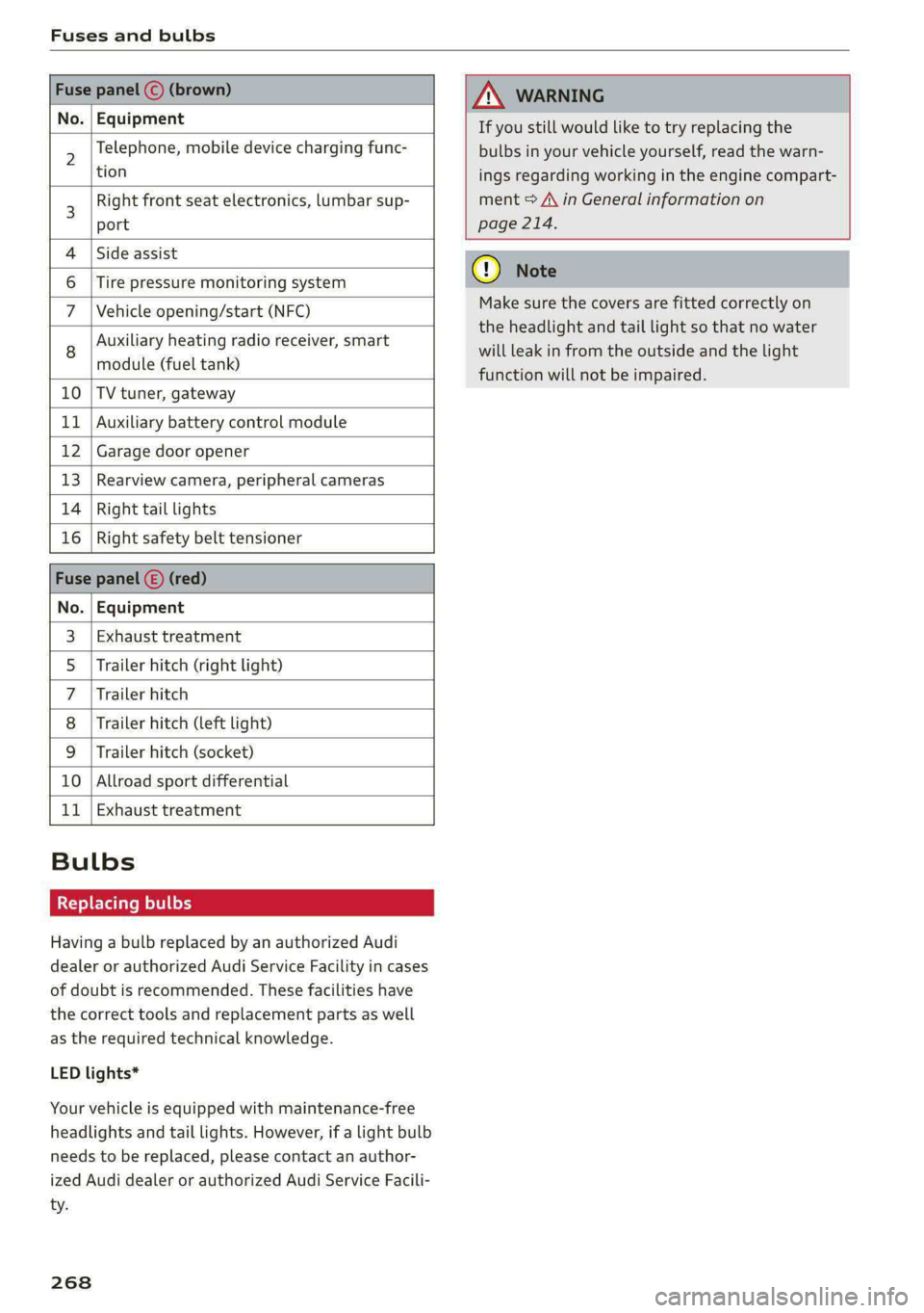
Fuse panel © (brown)
No. | Equipment
Telephone, mobile device charging func-
AN WARNING
If you still would like to try replacing the
bulbs in your vehicle yourself, read the warn-
6 |Tire pressure monitoring system
7 |Vehicle opening/start (NFC)
Auxiliary heating radio receiver, smart
module (fuel tank)
10 |TV tuner, gateway
11 | Auxiliary battery control module
12 | Garage door opener
13 | Rearview camera, peripheral cameras
14 | Right tail lights
16 | Right safety belt tensioner
Fuse panel (E) (red)
No. | Equipment
Exhaust treatment
Trailer hitch (right light)
Trailer hitch
Trailer hitch (left light)
Trailer hitch (socket)
10 |Allroad sport differential
11 | Exhaust treatment
Wl)
OIN|
Mm]
w
Bulbs
Replacing bulbs
Having a bulb replaced by an authorized Audi
dealer or authorized Audi Service Facility in cases
of doubt is recommended. These facilities have
the correct tools and replacement parts as well
as the required technical knowledge.
LED lights*
Your vehicle is equipped with maintenance-free
headlights and tail lights. However, if a light bulb
needs to be replaced, please contact an author-
ized Audi dealer or authorized Audi Service Facili-
ty.
268
2 |,
tion ings regarding working in the engine compart-
3 Right front seat electronics, lumbar sup- ment > A\ in General information on
port page 214.
4 |Side assist
@) Note
Make sure the covers are fitted correctly on
the headlight and tail light so that no water
will leak in from the outside and the light
function will not be impaired.
Page 280 of 296

Technical data
Fuel tank 15.3 gal (58 L)
Windshield and headlight washer system* 5.1 qt (4.8L)
The maximum permitted roof load is 198 lb
(90 kg).
| Ife Lie
Applies to: sedan
Fig. 193 Safety certificate
B8U-0380
Applies to: allroad
Fig. 194 Safety certificate
Gross Vehicle Weight Rating (GVWR)
The maximum permitted total weight @ of the
vehicle is listed on the safety certificate on the
side area of the door or on the driver's door pillar.
Gross Axle Weight Rating (GAWR)
The maximum permitted load on the front axle
@ or the rear axle @) is listed on the safety cer-
tificate on the side area of the door or on the
driver's door pillar.
Load
The maximum permitted load is listed on the tire
pressure label on the driver's door pillar.
278
Page 281 of 296

8W1012721BB
Index
Numbers and
Symbols
3-zone deluxe automatic climate control.... 88
A
ALC cooling MOde ss « « vesiev «sass w © wernin eon 88
Accelerator pedals sais se cai sv aac oe ews 96
also refer to Accelerator pedal........... 96
AGCOSSONIES «vce. «0 cesses « wesese ao nreree © 5 78,274
Active lane assist
refer to Audi active lane assist.......... 137
Adaptive cruise control................. 127
Adaptive dampers............-.0000005 106
Adjusting air distribution (automatic climate
control system) ......... 0.0.00. e eee ee 89
Adjusting the brightness................. 52
Adjusting the sound..............-...0- 206
Adjusting the temperature (automatic climate
control system) ...... 0.0 e cee eee eee 89
Adjusting the volume..............000005 26
Aitbagsystemn « «: swersve « sxaneus + cuneons wx anecome o 67
Alarm system
refer to Anti-theft alarm system.......... 33
Alignment pin (changing the wheel)....... 253
Alleweatherlightscses ws ances © sonasie » i axssane a 48
All Season tireSiens ss emans e e emie eo enews oo 242
All wheel drive
refer to quattro... . 2... eee eee ee eae 108
AMI
refer to Audi music interface........... 196
Android Auto
refer to Audi smartphone interface...... 204
Anti-freeze
Windshield washer system............. 225
Anti-lock braking system............00-5 109
Anti-Slip Regulation.................05. 109
Anti-theft alarm system..............000 33
Apple CarPlay
refer to Audi smartphone interface...... 204
Aspect ratio (video) ................ 199, 201
ASR
refer to Anti-Slip Regulation............ 109
Audi active lane assist..............0005 137
Cleaning the camera area.............. 248
Audi adaptive cruise control
Cleaning the sensors..............
Predictive control.............05.
Traffic jam assist.............00-.
Audi adaptive light.................
Audi connect
refer to connect...........eee eee
Audi connect Remote & Control
refer to Vehicle control services.....
Audi drive select...............0005
Audi music interface............00.
AudiosFileSviccs «x eon 2 wwe « o emcee 9 8 5
Safety measures..............005
Audi pre sense front..............0-
Audi side assist
refer to Side assist................
Audi smartphone interface..........
Legalinformation................
Audi virtual cockpit
refer to Instrument cluster.........
AUTO
Automatic climate control system...
Automatic headlights.............
Auto Lock (central locking) ..........
Automatic climate control system... .
Automatic luggage compartment lid....
Automatic transmission............
Automatic wipe/wash system........
Average consumption..............
AVETAGE SPEEd ss 5s aean sy ows Bee
B
Band
279
Page 283 of 296

8W1012721BB
Panoramic glass roof.................-. 44
Sliding/tilting sunroof...............005 43
Sunshade (rOOf)'s + ween a 2 wome a 2 cores va eee 44
WINdOWS « wscsese 2 6 ansree 6 o areene a a mmo 2 a aos 42
Gockpit diMMiNg:: « sw ss sews oa eee se es 52
Cockpit (OVEnVieW) « » wwe ss wee seen as cee 6
Collapsible spare tire...............0... 259
Collapsible tire
refer to Collapsible spare tire........... 259
GOlGrCOdG i: = «eee + xaen x 2 Bee a tee ees 277
Compact spare tite = sews y 2 emus se seems ¢ a oe 258
Compartments..............0-.02.0000- 78
Compass inthe mirror..............00005 57
Compliance ..... 0.0... cee eee eee eee 275
Conferencercallicics « o sosvese 0 0 semi a a mace ene 164
Configuration wizard « cccc.s «ews oo emi ae € 18
CONMECUiees ow smears 2 6 eames 3 He 2 6 HeaMEW © wens 169
Data plans........... ee eee eee eee 173
Data Privacyes ss ees sy ose s pees s 3 eee 271
Emergency:calll sess 2s mesic + ewrama » wenn « 174
Infotainment....................2005 169
Infotainment services... ..0... 6.0.5 cee 170
Online roadside assistance............. 175
Vehicle control services... cc... cee es T/L,
Connected devices
Device overvieW........-... 00-2 e eee ee 207
Connections
referto Media...............0-0- 195; 197
Consumer information.................. 272
Consumption
REGUGCING = gaan s 2 aams « noun 6 = Ree 4 5 ROR 99
Consumption (fuel) ........ 2.0.0 15
Contacts
Importing and exporting.............. 166
Updating inthe MMI.................. 166
also refer to Directory...............0. 163
Convenience key........ eee cece eee eee 30
Convenience closing..............++++- 42
also refer to Vehicle key................ 34
Convenience opening and closing
Windows or panoramic glass roof........ 42
Coolant temperature display.............. 13
Cooling system
Adding
coolant..............0.-. eee 221
Checking the coolant level............. 221
Coola Ntseiess 6 2 seine so sovsias eo cere @ x como 220 Cornering
lightics « «cose x 2 secs eo eerie oo ae 48
Cruise control system. ....... 000s ee eee 123
Cup Holdersiescs + ¢ saws s ¢ ees sy eee + e eww x 78
CUFPENECONSUMPLION ais < ease az new ox care 15
D
Data module
Serial number (IMEI) « weiss ss cncane a a wares @ 165
Data plans sss x 5 cows so ween 2s awn oo wee 173
Data Privacy’: « saws = = ses < ¢ sees x 2 eee ee 271;
Date wees : x ween 5 2 nes Fn ERR EES Eee 15
SOTUNG)s ¢ aston a 2 mas a i em @ 8 em & 4 ames 206
Daytime running lamps...............05- 48
Declaration of compliance...........0005 275
DEF CINStrUrMEnt ClUStED) |: saccu s x wows 5 x eae 11
Demo mode
refer to Presentation mode............. 186
Destination onthe map................. 179
DEtailSis : = mx = come 2 2 noe § E neR st me 179
Determining correct load limit........... 241
Digital compass .......... 00. eee eee eee 57
Dimensions............0..0.00..00000- 277
Dimming the exterior mirrors............. 53:
Dimming the rearview mirror............. 53
DineGtOr yin «+ secowi oo seme + o somes % & sense oo 5 163
Business card. ............00 2.00 e eee 163
Settings.......... 0.02.00. e eee eee 165
Display
Cleanings = » sees 5 = sews s = eews te eee ee 249
Displaying tooltips...............-..00- 18
Disposal
Distance Distance
warning .............0.0 eee ee 136
Doors
Child safety lock.............02.000000- 41
Door'contactiswiten s « sasay a « saws 4 & ara 4s SL.
Mechanically unlocking and locking....... 32
Driver information system................ 12
Drives
referto Media...........-...0-.. 195, 197
Drive select
refer to Audi drive select............... 106
Drive systeM.. 1... ee eee eee eee 98
Audi drive Select’: scws « ¢ swe ¢ v e@am ov oe 106
Drive system (message)................. 100