display AUDI A4 2020 Owner's Manual
[x] Cancel search | Manufacturer: AUDI, Model Year: 2020, Model line: A4, Model: AUDI A4 2020Pages: 296, PDF Size: 80.45 MB
Page 47 of 296
8W1012721BB
Opening and closing
You can switch the valet parking function on, for
example when someone else is parking your vehi-
cle ). The vehicle can be driven, locked, and un-
locked using the vehicle key, but access to the
luggage compartment is blocked.
> Remove the mechanical key > page 34.
> Press the [VALET] button in the glove compart-
ment. The LED in the button turns on if the
function is switched on.
> Lock the glove compartment with the mechani-
cal key.
» Applies to: vehicles with lockable pass-through
and lockable rear seat backrests: To secure the
luggage compartment from the vehicle interior,
lock the pass-through and the rear seat backr-
ests using the mechanical key > page 84 or
=> page 82.
> Give your vehicle key to the service personnel
who are parking your vehicle and keep the me-
chanical key.
The following buttons are deactivated when the
valet parking function is switched on:
— <3 button in the driver's door
— Zs button on the vehicle key
— Handle in the luggage compartment lid
If the valet parking function is switched on, a
message will appear every time the ignition is
switched on.
@ Tips
Please note that the luggage compartment
can still be accessed from the vehicle interior
in vehicles with fixed rear seat backrests or
ones that cannot be locked, even when the
valet parking function is switched on.
Garage door opener
Applies to: vehicles with garage door opener
With the garage door opener, you can activate
systems such as the garage doors, security sys-
D_ This function is not available in all countries.
2) The possible number of hand-held transmitters depends
on the equipment.
tems or house lights from inside your vehicle.
These functions are operated in the MMI. Multi-
ple receivers can be programmed, which can con-
trol the functions of up to eight2) hand-held
transmitters.
Z\ WARNING
— When operating or programming the garage
door opener, make sure that no people or
objects are in the area immediately sur-
rounding the equipment. People can be in-
jured or property can be damaged if struck
when closing.
— Do not allow yourself to be distracted from
traffic by the viewing and operating the dis-
plays.
G@) Tips
— Ifyou sell your vehicle, reset all settings to
the factory default settings > page 207.
—For an explanation on conformity with the
FCC regulations in the United States and the
Industry Canada regulations, see
=> page 275.
(i) Tips
Before you program your system to the ga-
rage door opener, first check the compatibili-
ty:
— Ask an authorized Audi dealer or authorized
Audi Service Facility or check at www.
homelink.com. You can also find more infor-
mation about HomeLink there.
— You can display information about Home-
Link (compatibility level/status/country
code/HomeLink generation) in the MMI:
— Select on the home screen: VEHICLE > Set-
tings & Service > Garage door opener > (.
Applies to: vehicles with garage door opener
Requirements: the remote control transmitter
must be programmed > page 46, the vehicle
4s
>
Page 48 of 296
Opening and closing
must be within range of the system, and the igni-
tion must be switched on.
There are multiple options to open or close the
system (such as the garage door).
> If you have only programmed one remote con-
trol transmitter, press the 2 button on the
display. Or
> If you have programmed multiple remote con-
trol transmitters, press the rs button on the
display and then press the respective system
button. Or
» Applies to: vehicles with programmable steer-
ing wheel button: If you have configured the
programmable steering wheel button, press
the * button > page 26. Or
> Applies to: vehicles with location pairing: If you
have programmed Location pairing, press the
button for this in the display (notification cen-
ter > page 20). As you approach the system,
the button is displayed on the MMI.
If transmission was successful, the message:
Send to: XXX will appear.
Applies to: vehicles with garage door opener
You can program both fixed code and rolling code
systems in the MMI using the procedure that is
described.
Requirement: the ignition must be switched on.
Programming the system
Applies to: MMI
Requirement: the hand transmitter must be
present and the vehicle must be within range of
the system (such as the garage door) that you
would like to program.
> If you are programming the garage door opener
for the first time, press the 7 button on the
display. Follow the instructions in the MMI. Or
> If you would like to program other systems, se-
lect on the home screen: VEHICLE > Settings &
Service > Garage door opener. Select the de-
D_ Only applies to rolling code systems
46
sired button: @). Follow the instructions in the
MMI.
> If you would like to reprogram systems that are
already programmed, select on the home
screen: VEHICLE > Settings & Service > Garage
door opener. Press the Z button and select 7
for the system to be reprogrammed. Select:
Program. Follow the instructions in the MMI.
With some systems, the garage door opener will
be immediately available after programming.
With other systems, the garage door opener
must also be synchronized.
Synchronizing)
Requirement: the hand transmitter must already
be programmed and the vehicle must be within
range of the system (such as the garage door).
If the system synchronization is performed di-
rectly after the programming procedure, follow
the instructions on the MMI.
If you would like to sync at a later time:
> Applies to: MMI: Select on the home screen:
VEHICLE > Settings & Service > Garage door
opener.
> Press the button for the system that you would
like to synchronize.
> Follow the instructions in the MMI.
Renaming programmed systems
You can rename the programmed systems indi-
vidually (names may have a maximum of 10 char-
acters).
> Applies to: MMI: Select on the home screen:
VEHICLE > Settings & Service > Garage door
opener.
> Press the Z button.
> Press the “ button for the system that you
would like to rename.
> Select: Rename. If necessary, delete the preset
name, such as Garage door opener 1.
> Follow the instructions in the MMI.
Page 49 of 296
8W1012721BB
Opening and closing
Location pairing
Applies to: vehicles with GPS pairing
For easier operation, you can program your sys-
tem's location.
Requirements: the respective hand transmitter
must be programmed > page 46 and the vehicle
must be located in front of the system.
» Applies to: MMI: Select on the home screen:
VEHICLE > Settings & Service > Garage door
opener.
> Press the Z button.
> Press the # button for the system your vehicle
is facing.
> Select: Location pairing.
> Follow the instructions in the MMI.
Only a maximum of three systems can be dis-
played in the notification center > page 20. If
you would like to have all systems displayed,
press a3.
Deleting programmed systems
The programmed systems can be deleted individ-
ually or all at once.
> Applies to: MMI: Select on the home screen:
VEHICLE > Settings & Service > Garage door
opener.
> Press the Z button.
> To delete an individual system, press the L]
button for the desired system. If the checkmark
¥ is set, select: Delete.
> To delete all systems, select: All > Delete.
@ Tips
— Make sure the batteries in the hand trans-
mitter are charged before starting the pro-
gramming process.
— The programming process may take up to
30 seconds. It may be necessary for the
hand transmitter to be pressed again in the
meantime.
— The garage door opener may need to be
synchronized with the system after pro-
gramming. Follow the manufacturer's in-
structions for doing this.
@) Tips
In some cases, the system may need to be
programmed in a different mode (“D mode”).
— Switch the ignition on.
— Applies to: MMI: Select on the home screen:
VEHICLE > Settings & Service > Garage
door opener.
— Press and hold the desired button @).
— Select Yes, in D mode and follow the in-
structions on the MMI.
47
Page 51 of 296
8W1012721BB
Lights and Vision
Turn signal and high beam lever
BFV-0012
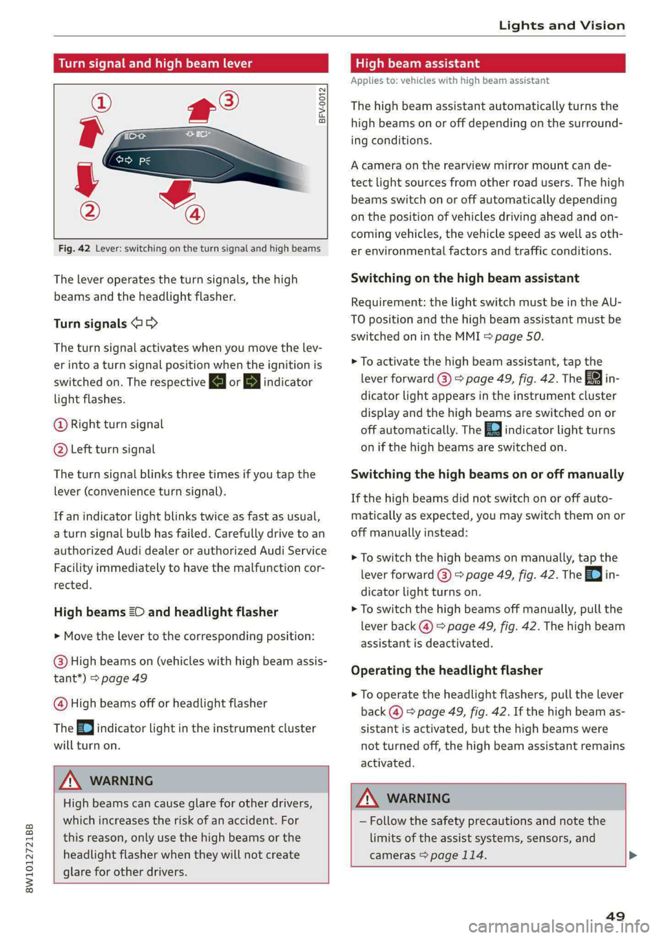
Fig. 42 Lever: switching on the turn signal and high beams
The lever operates the turn signals, the high
beams and the headlight flasher.
Turn signals 15>
The turn signal activates when you move the lev-
er into a turn signal position when the ignition is
switched on. The respective a or B indicator
light flashes.
@ Right turn signal
@® Left turn signal
The turn signal blinks three times if you tap the
lever (convenience turn signal).
If an indicator light blinks twice as fast as usual,
a turn signal bulb has failed. Carefully drive to an
authorized Audi dealer or authorized Audi Service
Facility immediately to have the malfunction cor-
rected.
High beams 20 and headlight flasher
> Move the lever to the corresponding position:
@) High beams on (vehicles with high beam assis-
tant*) > page 49
@ High beams off or headlight flasher
The
=o) indicator light in the instrument cluster
will turn on.
Z\ WARNING
High beams can cause glare for other drivers,
which increases the risk of an accident. For
this reason, only use the high beams or the
headlight flasher when they will not create
glare for other drivers.
teh m eu ielad
Applies to: vehicles with high beam assistant
The high beam assistant automatically turns the
high beams on or off depending on the surround-
ing conditions.
A camera on the rearview mirror mount can de-
tect light sources from other road users. The high
beams switch on or off automatically depending
on the position of vehicles driving ahead and on-
coming vehicles, the vehicle speed as well as oth-
er environmental factors and traffic conditions.
Switching on the high beam assistant
Requirement: the light switch must be in the AU-
TO position and the high beam assistant must be
switched on in the MMI > page 50.
> To activate the high beam assistant, tap the
lever forward @) > page 49, fig. 42. The FM in-
dicator light appears in the instrument cluster
display and the high beams are switched on or
off automatically. The Ea indicator light turns
on if the high beams are switched on.
Switching the high beams on or off manually
If the high beams did not switch on or off auto-
matically as expected, you may switch them on or
off manually instead:
> To switch the high beams on manually, tap the
lever
forward @) > page 49, fig. 42. The Ea in-
dicator light turns on.
> To switch the high beams off manually, pull the
lever back @) > page 49, fig. 42. The high beam
assistant is deactivated.
Operating the headlight flasher
> To operate the headlight flashers, pull the lever
back @) > page 49, fig. 42. If the high beam as-
sistant is activated, but the high beams were
not turned off, the high beam assistant remains
activated.
ZA WARNING
— Follow the safety precautions and note the
limits of the assist systems, sensors, and
cameras > page 114. >
49
Page 52 of 296
Lights and Vision
— High beam assistant is only intended to as-
sist the driver. The driver is still responsible
for controlling the headlights and may need
to switch them on and off manually depend-
ing on light and visibility conditions.
— High beams can cause glare for other driv-
ers, which increases the risk of an accident.
For this reason, only use the high beams or
the headlight flasher when they will not cre-
ate glare for other drivers.
@ Tips
Certain settings are automatically stored and
assigned to the active user.
Adjusting the exterior lighting
You can adjust the exterior lighting separately.
The settings depend on the vehicle equipment.
» Applies to: MMI: Select on the home screen:
VEHICLE > Light & Visibility > Exterior light-
ing.
Automatic headlights
You can adjust the following settings in the Auto-
matic
headlights menu:
Activation time - You can adjust if the headlights
switch on Early, Medium, or Late based on the
sensitivity of the light sensor.
High beam assistant - You can switch the high
beam assistant on and off.
Entry/exit lighting
When it is dark, the Entry/exit lighting illumi-
nates the area around the vehicle when unlocking
the vehicle and after switching off the ignition
and opening the driver's door. The entry/exit
lighting only works when it is dark and the light
switch is in the AUTO position.
Daytime running lights
USA models: The daytime running lights can be
switched on and off.
Canada models: This function cannot be switched
off. They activate automatically each time the ig-
nition is switched on.
sO
G) Tips
Certain settings are automatically stored and
assigned to the active user.
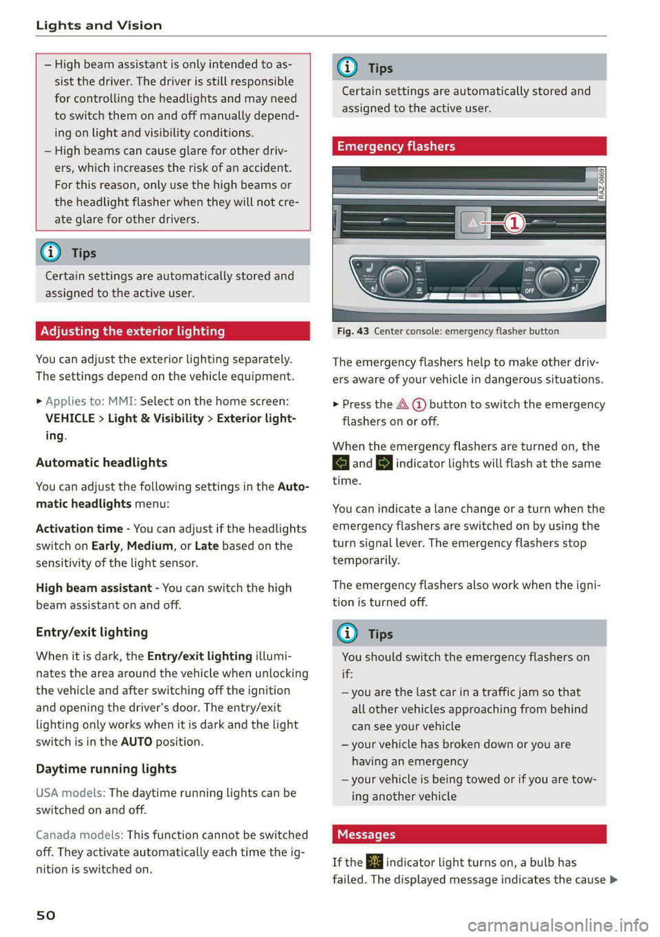
Emergency flashers
Fig. 43 Center console: emergency flasher button
The emergency flashers help to make other driv-
ers aware of your vehicle in dangerous situations.
> Press the A @ button to switch the emergency
flashers on or off.
When the emergency flashers are turned on, the
a and B indicator lights will flash at the same
time.
You can indicate a lane change or a turn when the
emergency flashers are switched on by using the
turn signal lever. The emergency flashers stop
temporarily.
The emergency flashers also work when the igni-
tion is turned off.
G) Tips
You should switch the emergency flashers on
if:
— you are the last car in a traffic jam so that
all other vehicles approaching from behind
can see your vehicle
— your vehicle has broken down or you are
having an emergency
— your vehicle is being towed or if you are tow-
ing another vehicle
If the 2] indicator light turns on, a bulb has
failed. The displayed message indicates the cause >
Page 54 of 296
Lights and Vision
Interior lighting
Applies to: vehicles with interior lighting
The ambient lighting turns on when the ignition
is switched on. The ambient lighting is deactivat-
ed when the light function is OFF.
You can adjust the interior lighting individually.
The settings depend on the vehicle equipment.
> Applies to: MMI: Select on the home screen:
VEHICLE > Light & Visibility > Interior light-
ing.
You can choose among predefined color profiles,
such as Maritime.
Additional settings and profiles:
— Brightness: you can adjust the brightness for
all of the interior lighting.
— Individual: you can adjust the brightness and
color of the interior lighting separately, divided
into contour and surface lighting.
— Drive select: the contour and surface lighting
color changes depending on the selected Audi
drive select* mode.
@ Tips
— Depending on vehicle equipment, when the
Drive select function is activated, the color
of the contour and surface lighting may
briefly change to red or blue when the inte-
rior temperature is manually increased or
decreased.
— Certain settings are automatically stored
and assigned to the active user.
Display brightness
You can adjust the instrument and display illumi-
nation separately. The settings depend on the ve-
hicle equipment.
> Applies to: MMI: Select on the home screen:
SETTINGS > Display & brightness.
Possible settings in the MMI:
— Cockpit dimming
— Head-up display
—MMI
— Virtual cockpit
52
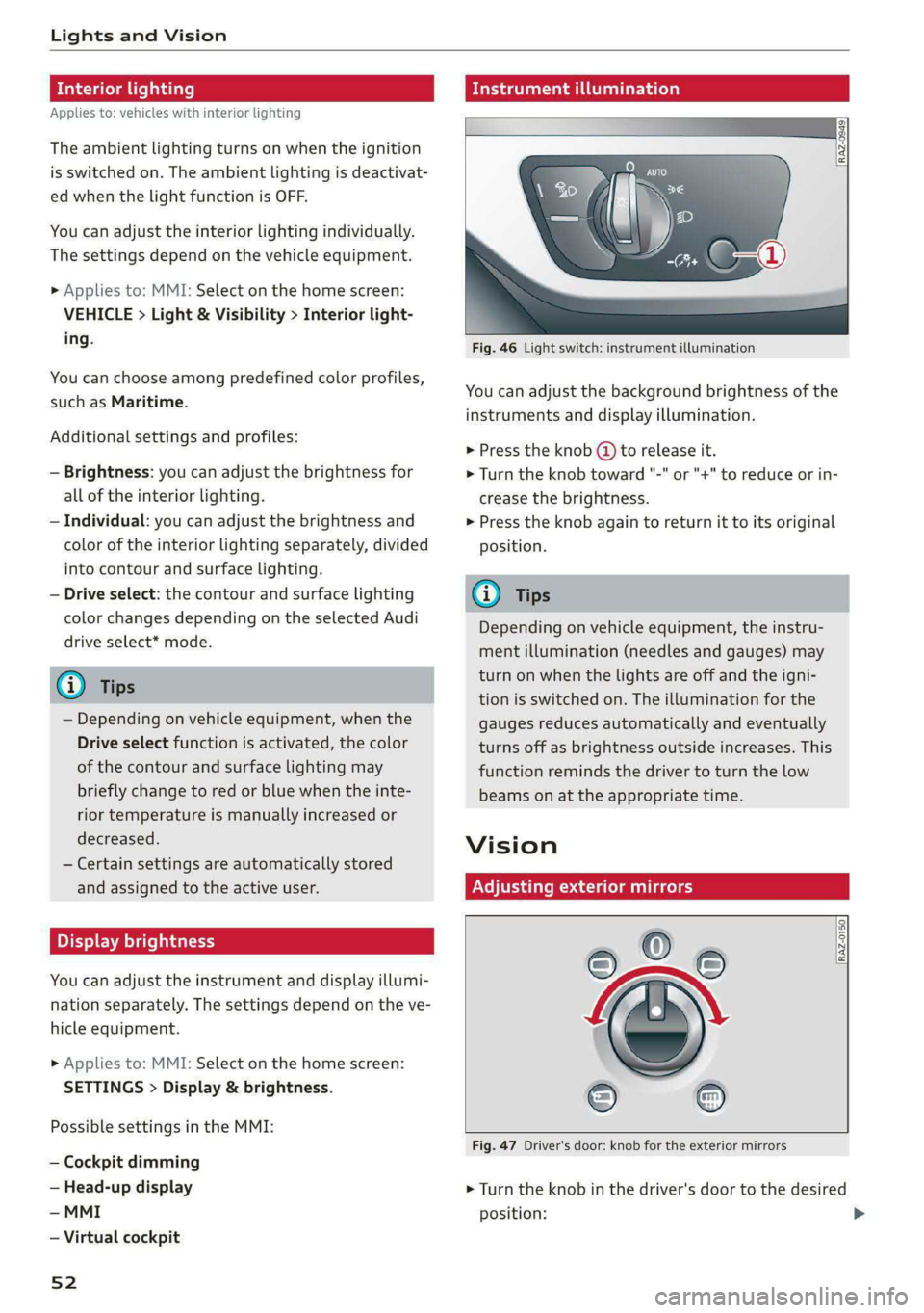
Mideast ar a
Fig. 46 Light switch: instrument illumination
You can adjust the background brightness of the
instruments and display illumination.
> Press the knob (@ to release it.
> Turn the knob toward "-" or "+" to reduce or in-
crease the brightness.
> Press the knob again to return it to its original
position.
@ Tips
Depending on vehicle equipment, the instru-
ment illumination (needles and gauges) may
turn on when the lights are off and the igni-
tion is switched on. The illumination for the
gauges reduces automatically and eventually
turns off as brightness outside increases. This
function reminds the driver to turn the low
beams on at the appropriate time.
Vision
Adjusting exterior mirrors
RAZ-0150
Fig. 47 Driver's door: knob for the exterior mirrors
> Turn the knob in the driver's door to the desired
position:
Page 59 of 296
8W1012721BB
Lights and Vision
@) Note
— The windshield wipers must only be folded
up when in the service position! Otherwise,
you risk damaging the paint on the hood or
the windshield wiper motor.
— You should not move your vehicle or press
the windshield wiper lever when the wiper
arms are folded up from the windshield. The
windshield wipers would move back into
their original position and could damage the
hood and windshield.
@ Tips
— You can also use the service position, for ex-
ample, if you want to protect the windshield
from icing by using a cover.
— You cannot activate the service position
when the hood is open.
Cleaning/ch g rear wiper blade
Applies to: vehicles with rear window wiper
B8R-0380
Fig. 53 Rear window wiper: installing the wiper blade
Cleaning the wiper blades
> Fold the wiper arm away from the rear window.
> For information on cleaning, see > table on
page 248.
Removing the wiper blade
> Fold the wiper arm away from the rear window.
>» Remove the wiper blade from its holder.
Installing the wiper blade
> Press the wiper blade mount into the retainer.
> Fold the window wiper arm back onto the rear
window.
ZX WARNING
For safety reasons, the windshield wiper
blades should be replaced once or twice each
year.
Messages
If the > indicator light turns on, then there is a
windshield wiper malfunction. The displayed
message indicates the cause and possible solu-
tions. If one of the messages does not turn off,
drive immediately to an authorized Audi dealer or
authorized Audi Service Facility to have the mal-
function repaired.
a Automatic wipers: malfunction! See owner's
manual
The light/rain sensor is malfunctioning. You can
still control all functions that are independent of
the rain sensor through the windshield wiper lev-
er. Drive immediately to an authorized Audi deal-
er or authorized Audi Service Facility to have the
malfunction repaired.
Digital compass
Sialic ma meelil eel mela
Applies to: vehicles with digital compass
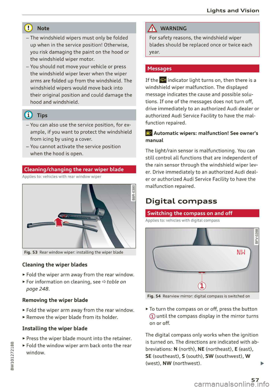
BFV-0288
Fig. 54 Rearview mirror: digital compass is switched on
> To turn the compass on or off, press the button
@ until the compass display in the mirror turns
on or off.
The digital compass only works when the ignition
is turned on. The directions are indicated with ab-
breviations: N (north), NE (northeast), E (east),
SE (southeast), S (south), SW (southwest), W
(west), NW (northwest).
57
Page 60 of 296
Lights and Vision
To prevent inaccurate compass readings, do
not bring any remote controls, electrical devi-
ces or metallic objects near the mirror.
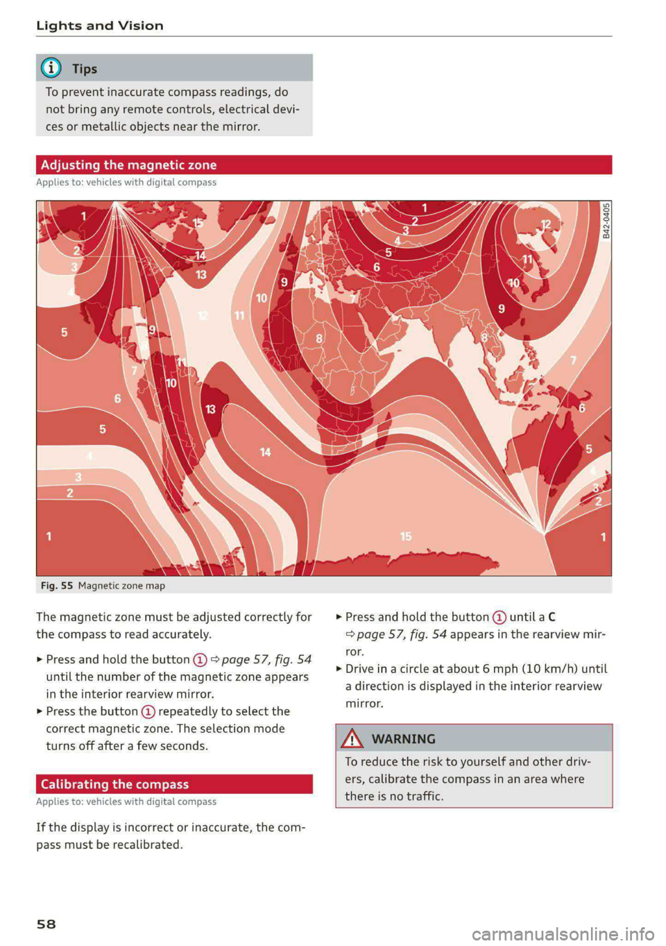
B42-0405
Fig. 55 Magnetic zone map
The magnetic zone must be adjusted correctly for > Press and hold the button @ until a C
the compass to read accurately. => page 57, fig. 54 appears in the rearview mir-
ror.
> Drive in a circle at about 6 mph (10 km/h) until
a direction is displayed in the interior rearview
mirror.
> Press and hold the button @ > page 57, fig. 54
until the number of the magnetic zone appears
in the interior rearview mirror.
> Press the button @ repeatedly to select the
correct magnetic zone. The selection mode
turns off after a few seconds.
To reduce the risk to yourself and other driv-
ers, calibrate the compass in an area where eat hark ree
there is no traffic. Applies to: vehicles with digital compass
If the display is incorrect or inaccurate, the com-
pass must be recalibrated.
58
Page 62 of 296
Sitting correctly and safely
— Your thighs are lightly supported by the front
surface of the seat
— The backrest is in an upright position and your
back is resting against it
— You have a sufficient view of the area around
the vehicle
— You have a clear view of the instrument cluster,
indicator lights, and the head-up display*
ZA WARNING
— If you are too close to the steering wheel or
instrument panel, the airbag system cannot
provide the optimal protection, which in-
creases the risk of injury and death.
— To reduce the risk of injury in the event of
sudden braking maneuvers or accidents,
never drive with the backrest reclined very
far. The airbag system and seat belts can on-
ly provide optimal protection when the back-
rest is in an upright position and the driver
is wearing the seat belt correctly. If the
backrest is angled back too far, the safety
belt can shift to soft areas of the body, such
as the stomach, which increases the risk of
injury.
—To reduce the risk of an accident, only adjust
the seats when the vehicle is stationary.
— Be careful when adjusting the seat. Lack of
control or attention when adjusting can re-
sult in injuries due to pinching to vehicle oc-
cupants both in the front seats and rear
seats.
— Never place objects in the driver's footwell.
Objects could shift and enter the area
around the pedals, which could prevent you
from using them. You would then be unable
to use the pedals if sudden driving or brak-
ing maneuvers were needed, which increas-
es the risk of an accident.
— Make sure that the floor mats are always se-
curely attached.
— To reduce the risk of an accident, never place
additional floor mats or other floor covers
over the installed floor mats, because this
reduces the pedal's range of motion and can
impair pedal operation.
—To reduce the risk of injury, never place your
feet on the instrument panel, out of the
60
window, or on the seat surfaces. This also
applies to passengers in the rear seats.
@) Note
Applies to: vehicles with manually adjustable head re-
straints
To reduce the risk of damage, be very careful
when adjusting the seat to make sure the
head restraints do not hit the headliner or the
panorama glass roof*.
oN eet Lar feet ana)
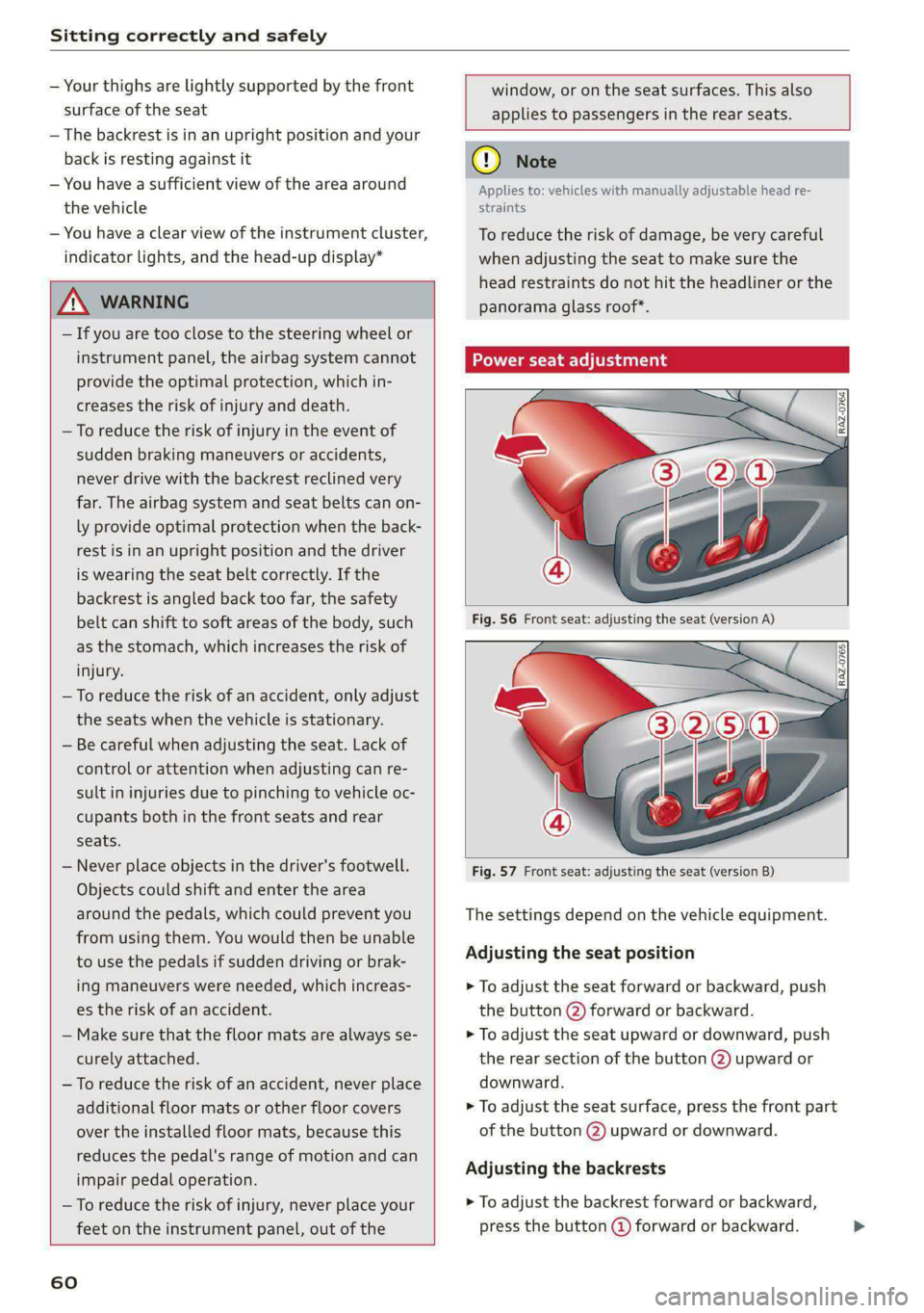
Fig. 57 Front seat: adjusting the seat (version B)
The settings depend on the vehicle equipment.
Adjusting the seat position
> To adjust the seat forward or backward, push
the button @) forward or backward.
> To adjust the seat upward or downward, push
the rear section of the button @) upward or
downward.
> To adjust the seat surface, press the front part
of the button @) upward or downward.
Adjusting the backrests
> To adjust the backrest forward or backward,
press the button @ forward or backward. >
Page 63 of 296
8W1012721BB
Sitting correctly and safely
Adjusting the upper thigh support
> To increase or decrease the upper thigh sup-
port, lift the handle @) and move the upper
thigh support.
Massage function
> To switch the massage function on or off, press
the button © ° fig. 57.
Adjusting the lumbar support
> To adjust the lumbar support, press the button
@ at the applicable location.
Adjusting the side supports
You can adjust the side bolsters using the multi-
function button @) > fig. 57.
Z\ WARNING
—To reduce the risk of an accident, only adjust
the driver's seat when the vehicle is station-
ary.
— The power front seats can also be adjusted
when the ignition is switched off. To reduce
the risk of injury, children should never be
left unattended in the vehicle for this rea-
son.
— Exercise caution when adjusting the seat
height. Unsupervised or careless seat adjust-
ment could cause parts of the body to get
pinched, which increases the risk of injury.
— The front seat backrests must not be re-
clined too far back when driving, because
this impairs the effectiveness of the safety
belts and airbag system, which increases the
risk of injury.
Adjusting the front seats in the MMI
Applies to: vehicles with seat settings in the MMI
You can adjust additional settings in the MMI.
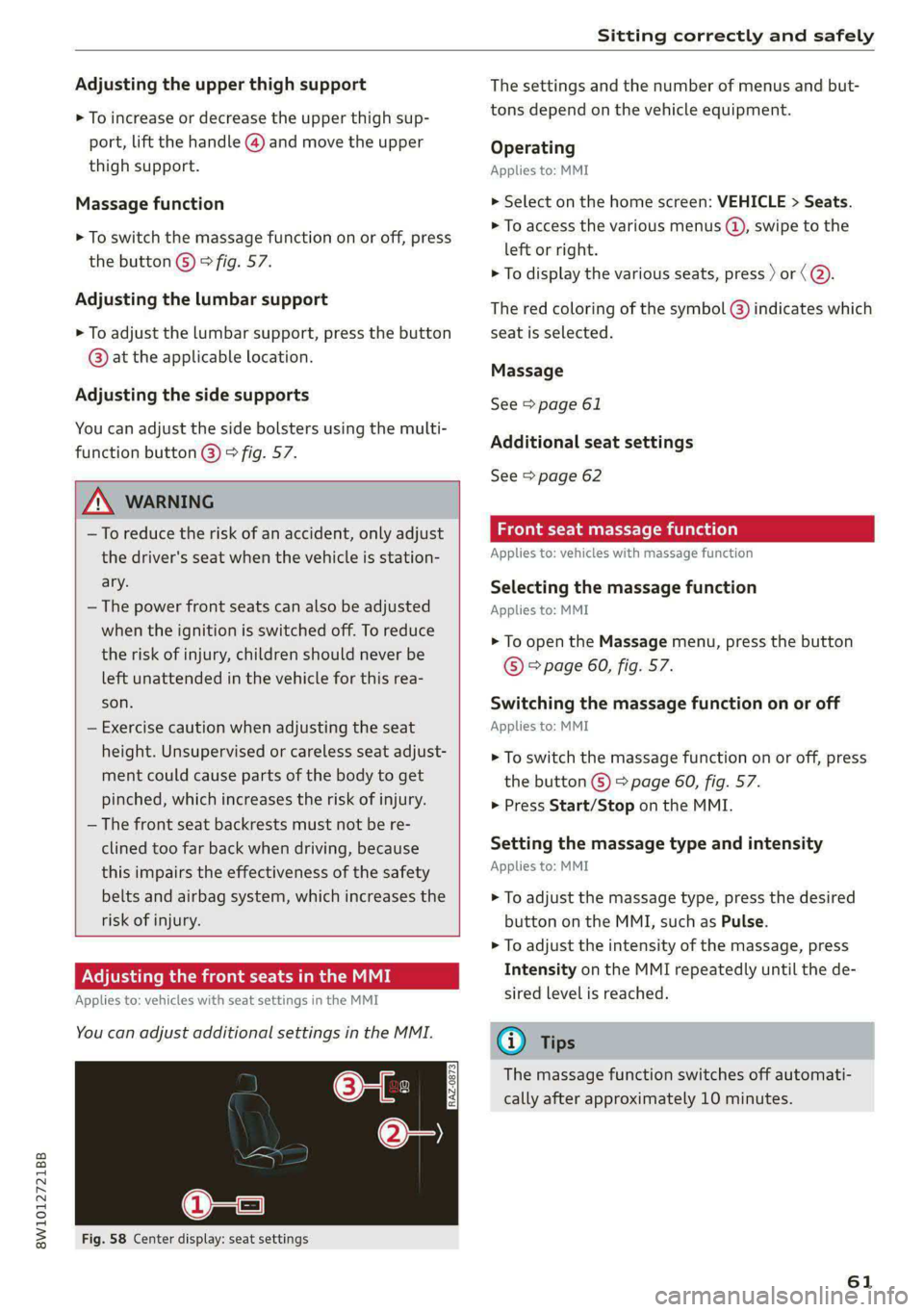
Fig. 58 Center display: seat settings
The settings and the number of menus and but-
tons depend on the vehicle equipment.
Operating
Applies to: MMI
> Select on the home screen: VEHICLE > Seats.
> To access the various menus (4), swipe to the
left or right.
> To display the various seats, press ) or ( @.
The red coloring of the symbol @) indicates which
seat is selected.
Massage
See > page 61
Additional seat settings
See > page 62
eae emia (ola)
Applies to: vehicles with massage function
Selecting the massage function
Applies to: MMI
> To open the Massage menu, press the button
© > page 60, fig. 57.
Switching the massage function on or off
Applies to: MMI
> To switch the massage function on or off, press
the button G) > page 60, fig. 57.
> Press Start/Stop on the MMI.
Setting the massage type and intensity
Applies to: MMI
> To adjust the massage type, press the desired
button on the MMI, such as Pulse.
> To adjust the intensity of the massage, press
Intensity on the MMI repeatedly until the de-
sired level is reached.
@) Tips
The massage function switches off automati-
cally after approximately 10 minutes.
61