display AUDI A4 2021 Owner´s Manual
[x] Cancel search | Manufacturer: AUDI, Model Year: 2021, Model line: A4, Model: AUDI A4 2021Pages: 304, PDF Size: 107.89 MB
Page 4 of 304
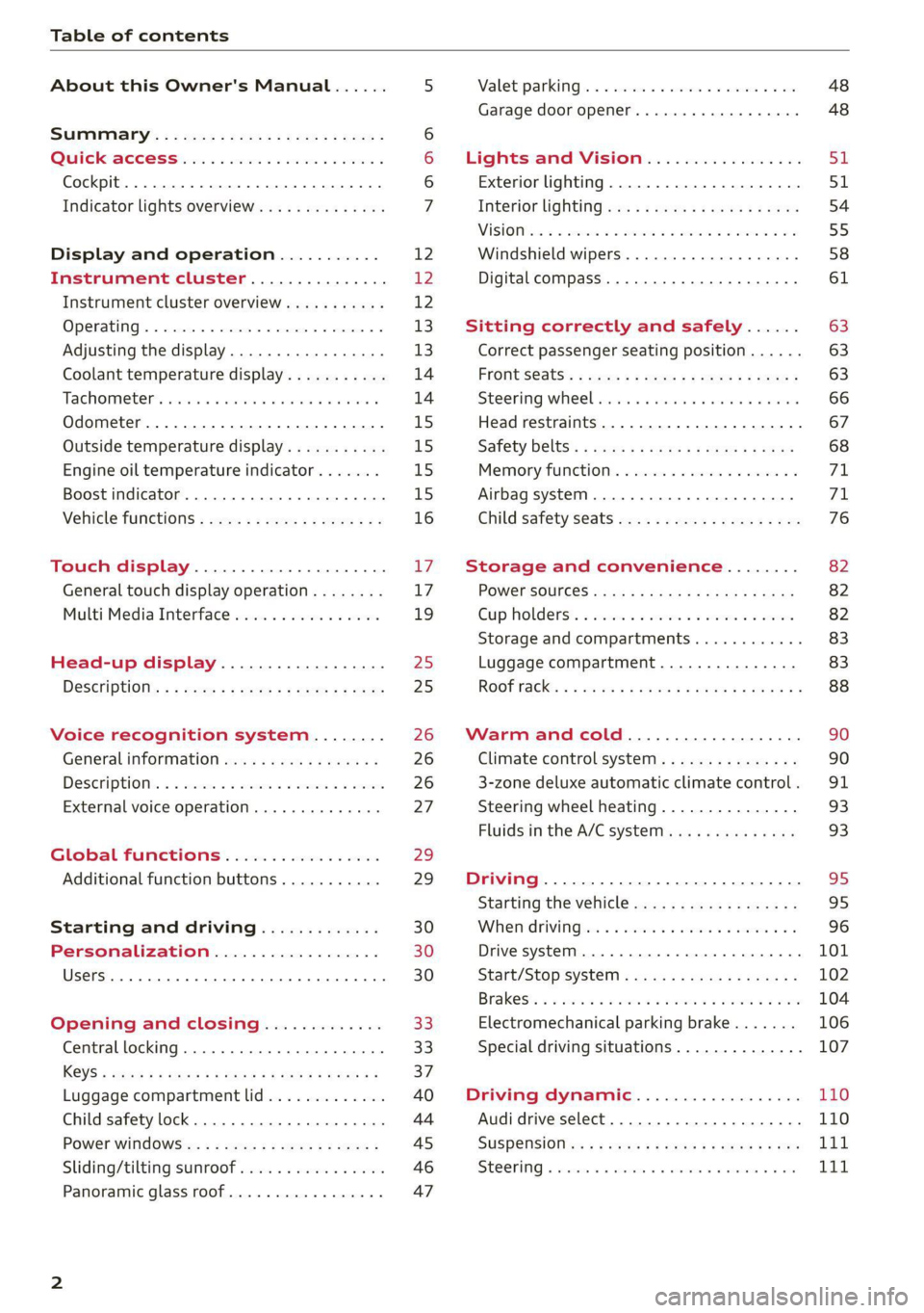
Table of contents
About this Owner's Manual......
SUMIMAry: < = exe : eens: Seen cs sens
QutckeaeCe ssh: «i esis se ois a eaves @
Cockpit. ...... 0... eee eee eee eee
Indicator lights overview...........4..
Display and operation...........
Instrument cluster...............
Instrument cluster overview...........
Operating. ecccuse w+ were oo wens oo ayes 9 ¥
Adjusting the display.................
Coolant temperature display...........
Tachometer’ series i ewe so snes ¥ & ome
Odometer.............. cee eee eee ee
Outside temperature display...........
Engine oil temperature indicator.......
Boost indicator...............0--000.
Vehicle functions...............-----
Touch display.....................
General touch display operation........
Multi Media Interface................
Head-up display..................
DeSeriptions: s wees « x wows ¢ cess so eee
Voice recognition system........
Generalinformation.................
DeSeriptions. «+ seams x x arucsms x 0 seine oo coer
External voice operation..............
Global FUNGtHIONS:. icc: 5 6 ese. 6 6 sce
Additional function buttons...........
Starting and driving.............
Personalization..................
Opening and closing.............
Central locking..............00-e eee
Child safety lock.............00.-000
Power WindOWSic« s < sews ys wey 5 2 em 5
Sliding/tilting:SUNTOOF escinie os wise a 6 soe
Panoramic glass roof.................
NOD
OO
12 12 12
13
13
14 14
15
15
15
15
16 17 17 19
Z5
25
26 26 26 27
29;
29
30 30 30
33
33)
37
40
44
45
46 47
Valetiparking = s ss-e «x cscs ov cree a ¥ os 48
Garage door opener..........--.00 eee 48
Lights and Vision................. 51
Exterior lighting...................4. 51
Interior liQhting ss =e aves ss eews so eos 54
ViSIOMsn « 3 ses 3 3 ema oo wena vo ae © ove 55
Windshield wipers.............-..45- 58
Digital compass.............-.-0000- 61
Sitting correctly and safely...... 63
Correct passenger seating position...... 63
Frontseats:: » ssw. « ¢ sews & » saws +s ewe < 63
Steering wheel seis < «cies ¥ eerie ss eee 66
Head restraints.................0000. 67
Safety Beltsi: s sass x eeups ¢ < saves 2 e cee 68
Memory function . « scons ecw ee cro ee 71
Airbag system... ... 2.62... 0 ee eee eee 7X
Child safety seats.................04- 76
Storage and convenience........ 82
POWErSOURCES coisa gs seen ss wae se aes 82
Gup holders. ¢ ssn ss wee 2 2 see 2 & pee 82
Storage and compartments............ 83
Luggage compartment............... 83
ROOF hacks « = weies x = wae 2 s eae 2 & ween 2 88
Warm and cold................... 90
Climate control system............... 90
3-zone deluxe automatic climate control. 91
Steering wheel heating............... 93
Fluids in the A/C system. .........0065 93
Driving .............. 0.0... eee eee 95
Starting the vehicle...............0.0. 95
When driving isis ss iovsvie se aerswce oo anes oe 96
Drive system... 2.2... ee eee eee eee 101
Start/Stop system .........ee cece eee 102
BrakeS's so isemi 2 wane w aman a 2 oer as ie 104
Electromechanical parking brake....... 106
Special driving situations.............. 107
Driving: dynamic. . « sic. 6 6 see a 6 se 110
Audi drive select..................00. 110
SUSPENSION es « + exes ¢ ¢ eres +o ees vv eae 111
SUECOMIING 6 vessse oo csisweue io & stone 6 a toma ww Bs Lid
Page 6 of 304
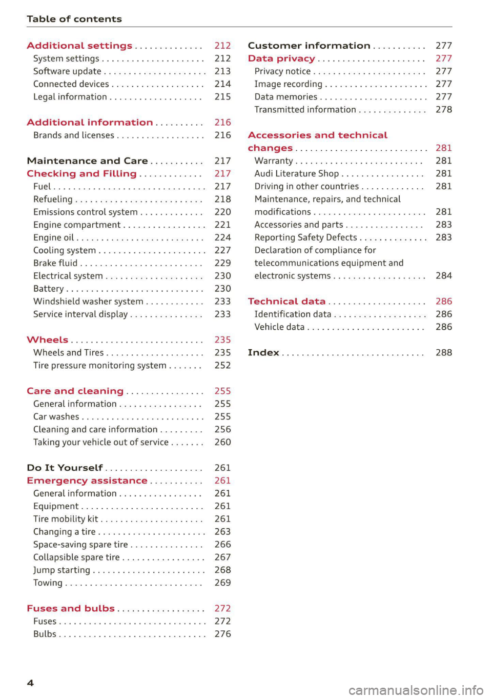
Table of contents
Additional settings.............. 212
System settingS.............ce ee eee 212
Software update... 1.2... .. cc cece ee eee 213
Connected devices.............000 005 214
Legalinformation................... 215
Additional information.......... 216
Brands and licenses..............0-0- 216
Maintenance and Care........... 217
Checking and Filling............. 217
LE 217
Refttelingiecs ss sees s eames s Reee ee ewe 218
Emissions control system............. 220
Engine compartment................. 221
ENGING2Otls sees 2 x seus « ones x ove Bee 224
Cooling:system « « ssccses ve emacs ve asecane s & ave 227
Brake fluid... 0.2... eee eee eee 229
Electrical system............22---05- 230
Battery’: « & ces «6 cow © 6 eee «8 eens ¥ oe 230
Windshield washer system...........- 233
Service interval display............... 233
WSENGRRES Ee ceicece 0 ccneace x 0 wprsnne x « scecane a 0 ane 235
Wheels and Tires . . 235
Tire pressure monitoring system....... 252
Care and cleaning................ 255
Generalinformation................. 255
Car washes « sscica ea scam a 0 eine oo acne 0 6 255
Cleaning and care information......... 256
Taking your vehicle out of service....... 260
Do It Yourself .................... 261
Emergency assistance........... 261
General information...........0..0.. 261
Equipment.............00- cece eee 261
Tire Mobility’ kit «0. ss cece se ces se ee 261
Changing’ tire = sco: +s ween so some 2 2 ore 263
Space-saving spare tire............... 266
Collapsible spare tire..............0.. 267
JUIMP'StAFting « wos s = weve s eerws F coos 268
TOWING wwewiwe «2 exersie w > suseine 6 > cxememe 6 4 cuneec 269
Fuses and bulbs.................. 272
FUSCSiercs ao accsans wo cena wo ee @ 8 ROIS & ore 272
Bulbs... 0.0... cee eee eee eee 276
Customer information........... 277
Data privacy..................008. 277
Privacy MOtiCe « mes x x eee 2 Ree ¢ RES ¥ 277
Image recording): « « sus 2 wanes 2 2 wweem 2 2s 277,
Data memories............0..00 eee ee 277
Transmitted information.............. 278
Accessories and technical
changes................ 0.0.02 eee 281
Warranty’: « + esos & + meen & ¢ eee se sees 281
Audi Literature Shop.............000- 281
Driving in other countries............. 281
Maintenance, repairs, and technical
IMOGIFICATIONS « snocue so sume = emmace # m annem 281
Accessories and parts..............-. 283
Reporting Safety Defects.............. 283
Declaration
of compliance for
telecommunications equipment and
electronicisysteMms:: s = caws se waa « 2 gems 284
Technical data.................... 286
Identification data................04. 286
Vehicle datas ss nico s ves se oman evs 286
Index ...... 00.0... eee eee 288
Page 8 of 304
Quick access
Quick access
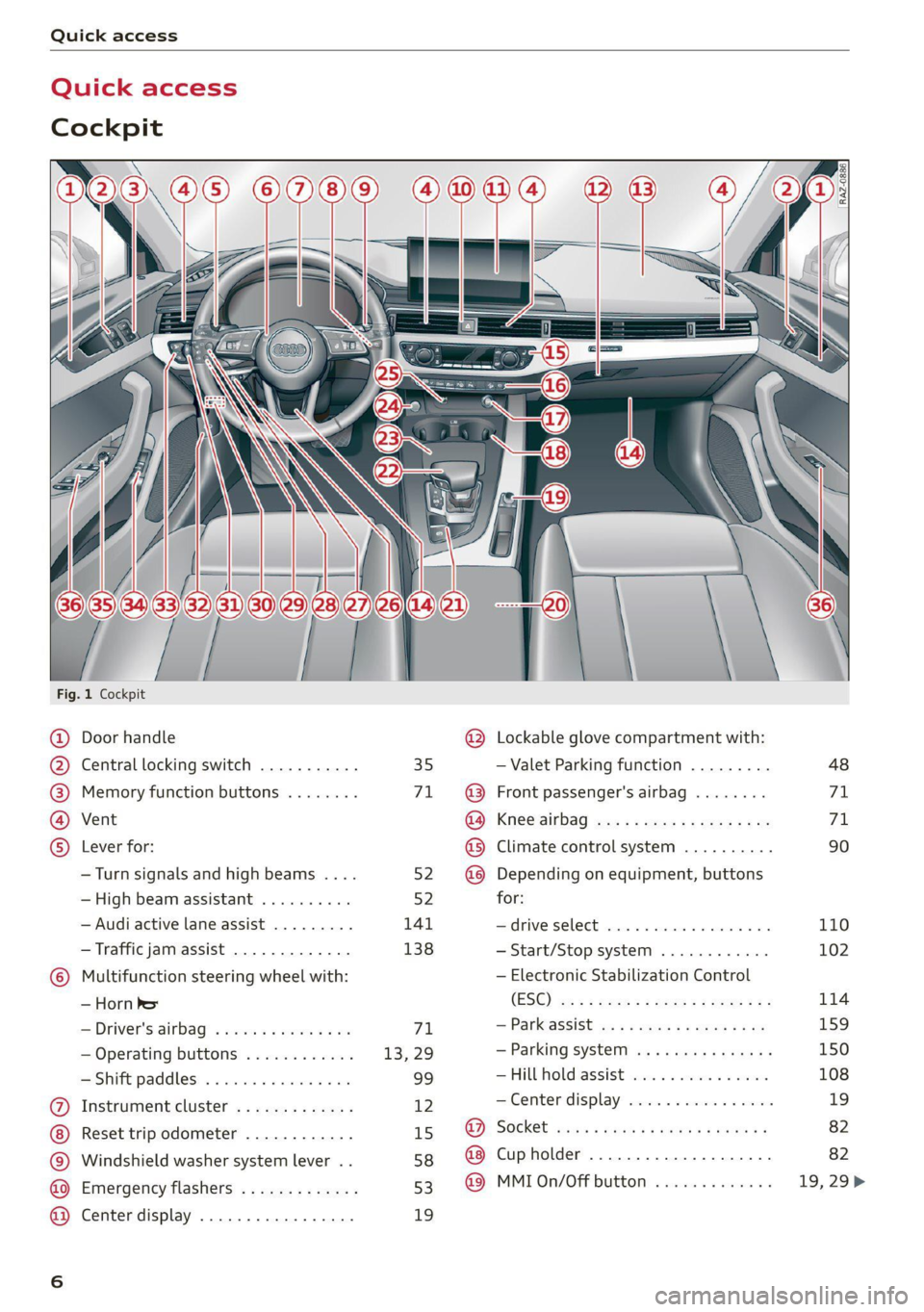
Cockpit
[RAZ-0886.
Fig. 1 Cockpit
@ Door handle @ Lockable glove compartment with:
@ Central locking switch ........... 35 — Valet Parking function ......... 48
@ Memory function buttons ........ 71. ~@ Front passenger's airbag ........ 71
@ Vent GO; KSC Sia auc 2 x wee so ews 2 ae 71
© Lever for: @® Climate control system .......... 90
—Turn signals and high beams .... 52. @@ Depending on equipment, buttons
— High beam assistant .......... 52 for:
— Audi active lane assist ......... 141 drive SELCCE cassis «6 sossan © 4 esr © 6s 110
— Traffic jam assist ............. 138 —Start/Stop system ............ 102
© Multifunction steering wheel with: — Electronic Stabilization Control
_iHorn' bet (ES@) we < = ween «seme se ee zea 114
—Driver's airbag .............0- 71 — Panassist ws 5 2 aque « s quae x # me 159
— Operating buttons ............ 13, 29 — Parking system ..........-..+. 150
—Shift paddles ................ 99 — FUL Fold aSSi8t cies 2 4 onus oo ees 108
@ Instrument cluster ............. 12 — Center display .............0 0s 19
Reset trip odometer ............ 15 @ Socket .......seeseeeee eens 82
© Windshield washer system lever .. 58 @ Cupholder ........ 0.0 seer eee 82
@ Emergency flashers ............ 53 @© MMI0n/Off button ............. 19,29>
@ Center display ................. 19
Page 9 of 304
8W1012721BC
Quick access
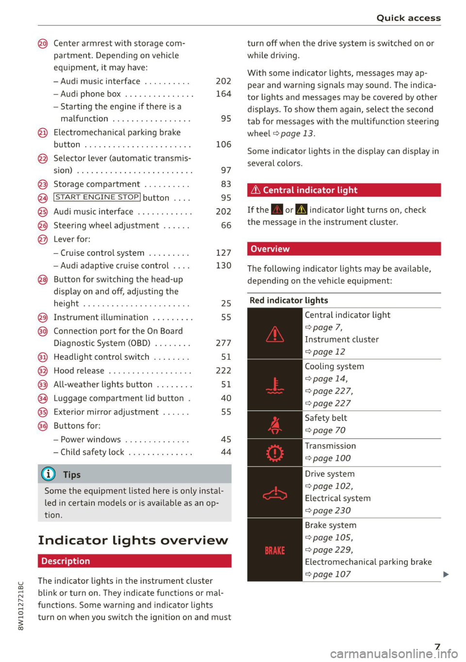
@9 Center armrest with storage com-
partment. Depending on vehicle
equipment, it may have:
— Audi music interface .......... 202
—Audi phone box ............... 164
— Starting the engine if there is a
MALFUMERION since oo sxosoue x 2 seems ss 95
@) Electromechanical parking brake
BUGGOT sieves so cman « 2 ewes 2s men 2 106
@) Selector lever (automatic transmis-
SIOM) seo so neon & v Howe & eRe Fa 97
@3 Storage compartment .......... 83
@ [START ENGINE STOP]button .... 95
@3) Audi music interface ............ 202
@@ Steering wheel adjustment ...... 66
@) Lever for:
— Cruise control system ......... 127
— Audi adaptive cruise control .... 130
® Button for switching the head-up
display on and off, adjusting the
height ........ 2... cee eee eee 25
@ Instrument illumination ......... 55
60) Connection port for the On Board
Diagnostic System (OBD) ........ 277
@) Headlight control switch ........ 51
@ Hood release ...............0-. 222
63 All-weather lights button ........ 51
@4 Luggage compartment lid button . 40
@5) Exterior mirror adjustment ...... 55
68 Buttons for:
— Power windows ...........00. 45
—Child safety lock .............. 44
@) Tips
Some the equipment listed here is only instal-
led in certain models or is available as an op-
tion.
Indicator lights overview
The indicator lights in the instrument cluster
blink or turn on. They indicate functions or mal-
functions. Some warning and indicator lights
turn on when you switch the ignition on and must
turn off when the drive system is switched on or
while driving.
With some indicator lights, messages may ap-
pear and warning signals may sound. The indica-
tor lights and messages may be covered by other
displays. To show them again, select the second
tab for messages with the multifunction steering
wheel > page 13.
Some indicator lights in the display can display in
several colors.
OMe eee any
If the wA or N indicator light turns on, check
the message in the instrument cluster.
The following indicator lights may be available,
depending on the vehicle equipment:
Red indicator lights
Central indicator light
=> page 7,
Instrument cluster
=>page 12
Cooling system
> page 14,
=> page 227,
=> page 227
Safety belt
=> page 70
Transmission
= page 100
Drive system
= page 102,
Electrical system
=> page 230
Brake system
=>page
105,
=>page 229,
Electromechanical parking brake
=> page 107 >
Page 14 of 304
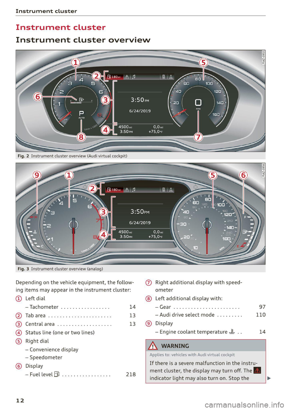
Instrument cluster
trument clu
Instrument cluster overview
Belo
6/24/2019
6/24/2019
C100 T
Fig. 3 Instrument cluster overview (analog)
Depending on the vehicle equipment, the follow- @) Right additional display with speed-
ing items may appear in the instrument cluster: ometer
Left dial @® Left additional display with:
—Tachometer .........00.. 000s 14 SIG OOM wice es eosenes 2 a were 2 8 wate @ oe 97
Tab
af@a « < sees se oes x eee gee 13 — Audi drive select mode ......... 110
Centralarea .............0.000. 13 Display
Status line (one or two lines) — Engine coolant temperature ~E .. 14
Right dial i
— Convenience display ZX WARNING
— Speedometer Applies to: vehicles with Audi virtual cockpit
Display If there is a severe ECD in the instru-
—FuellevelfD .....-..e0eeec ee. 218 ment cluster, the display may turn off. The
indicator
light may also turn on. Stop the >
12
Page 15 of 304
8W1012721BC
Instrument cluster
vehicle safely. See an authorized Audi dealer
or authorized Audi Service Facility for assis-
tance.
G) Tips
— The following pages primarily show illustra-
tions of the Audi virtual cockpit*. The dis-
play or location of the items that are shown
may vary on the different versions of the in-
strument cluster.
— You can select the units used for tempera-
ture, speed, and other measurements
=> page 212.
— Speeds are displayed in mph (miles per
hour) or km/h (kilometers per hour).
— Certain instrument cluster content can also
be displayed in the head-up display*
=>page 25.
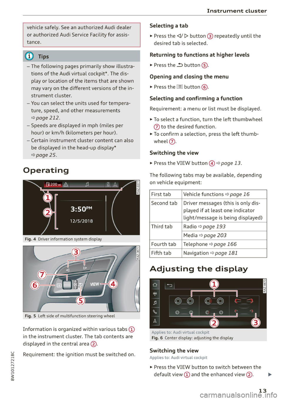
Operating
Fig. 5 Left side of multifunction steering wheel
Information is organized within various tabs @)
in the instrument cluster. The tab contents are
displayed in the central area (2).
Requirement: the ignition must be switched on.
RAZ-0377
Selecting a tab
> Press the
desired tab is selected.
Returning to functions at higher levels
> Press the D button ©).
Opening and closing the menu
» Press the [=] button ©).
Selecting and confirming a function
Requirement: a menu or list must be displayed.
> To select a function, turn the left thumbwheel
@ to the desired function.
> To confirm a selection, press the left thumb-
wheel (7).
Switching the view
> Press the VIEW button @) > page 13.
The following tabs may be available, depending
on vehicle equipment:
First tab Vehicle functions > page 16
Second tab | Driver messages (this is only dis-
played if at least one indicator
light/message is being displayed)
Third tab Radio > page 193
Media > page 203
Fourth tab | Telephone > page 166
Fifth tab Navigation > page 181
Adjusting the display
RAZ-0673
Applies to: Audi virtual cockpit
Fig. 6 Center display: adjusting the display
Switching the view
Applies to: Audi virtual cockpit
> Press the VIEW button to switch between the
default view @ and the enhanced view (2).
13
Page 16 of 304
Instrument cluster
Adjusting the layout
Applies to: Audi virtual cockpit
Depending on the vehicle equipment, various lay-
outs may be available.
> Applies to: MMI: Select on the home screen:
SETTINGS > Display & brightness > Audi virtu-
al cockpit.
> To adjust the desired layout, press @).
Adjusting the additional display
Applies to: Audi virtual cockpit
Depending on the vehicle equipment, the addi-
tional displays that can be selected may vary.
> Applies to: MMI: Select on the home screen:
SETTINGS > Display & brightness > Audi virtu-
al cockpit > Configure.
> Select the desired additional display.
Reducing the display
Depending on the vehicle equipment, you can
hide the central area in the instrument cluster.
> Select on the instrument cluster: vehicle func-
tions tab > [=] button > Reduced display, or
> Press the VIEW button on the multifunction
steering wheel.
Coolant temperature
display
Applies to: vehicles with a coolant temperature indicator
The coolant temperature display @) > page 12
only functions when the ignition is switched on.
To reduce the risk of engine damage, please ob-
serve the following notes about the temperature
ranges.
Cold range
If only the LEDs at the bottom of the gauge turn
on, the engine has not reached operating tem-
perature yet. Avoid high engine speeds, full accel-
eration, and heavy engine loads.
Normal range
The engine has reached its operating tempera-
ture once the LEDs up to the center of the gauge
turn on. If the | indicator light in the instru-
14
ment cluster display turns on, the coolant tem-
perature is too high > page 227.
() Note
— Auxiliary headlights and other accessories in
front of the air intake impair the cooling ef-
fect of the coolant. This increases the risk of
the engine overheating during high outside
temperatures and heavy engine load.
— The front spoiler also helps to distribute
cooling air correctly while driving. If the
spoiler is damaged, the cooling effect will
be impaired and the risk of the engine over-
heating will increase. See an authorized
Audi dealer or authorized Audi Service Fa-
cility for assistance.
Tachometer
The tachometer @) > page 12 displays the engine
speed in revolutions per minute (RPM). The be-
ginning of the red zone in the tachometer indi-
cates the maximum permissible engine speed for
all gears once the engine has been broken in. Be-
fore reaching the red zone, you should shift into
the next higher gear, select the "D" or "S" selec-
tor lever position, or remove your foot from the
accelerator pedal.
Engine speed limitation
If the tA indicator light turns on, the engine will
be automatically limited to the RPM displayed in
the instrument cluster. This will protect the en-
gine components, for example during a cold start
or from overheating.
The engine speed limitation is deactivated if you
release the accelerator pedal while the engine is
at normal operating temperature.
If the engine speed limitation was activated by
an engine control malfunction, the By indicator
light also turns on. Make sure the engine speed
does not go above the speed displayed, for exam-
ple when downshifting. Drive to an authorized
Audi dealer or authorized Audi Service Facility im-
mediately to have the malfunction corrected. >
Page 17 of 304
8W1012721BC
Instrument cluster
@) Note
The needle in the tachometer may only be in
the red area of the gauge for a short period of
time before there is a risk of damaging the
engine. The location where the red zone be-
gins varies depending on the engine.
Odometer
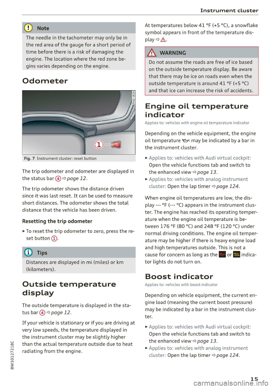
Fig. 7 Instrument cluster: reset button
The trip odometer and odometer are displayed in
the status bar @) > page 12.
The trip odometer shows the distance driven
since it was last reset. It can be used to measure
short distances. The odometer shows the total
distance that the vehicle has been driven.
Resetting the trip odometer
> To reset the trip odometer to zero, press the re-
set button @.
@) Tips
Distances are displayed in mi (miles) or km
(kilometers).
Outside temperature
display
The outside temperature is displayed in the sta-
tus bar @) 9 page 12.
If your vehicle is stationary or if you are driving at
very low speeds, the temperature displayed in
the instrument cluster may be slightly higher
than the actual temperature outside due to heat
radiating from the engine.
At temperatures below 41 °F (+5 °C), a snowflake
symbol appears in front of the temperature dis-
play > A\.
7 WARNING
Do not assume the roads are free of ice based
on the outside temperature display. Be aware
that there may be ice on roads even when the
outside temperature is around 41 °F (+5 °C)
and that ice can increase the risk of accidents.
Engine oil temperature
indicator
Applies to: vehicles with engine oil temperature indicator
Depending on the vehicle equipment, the engine
oil temperature %7% may be indicated by a bar in
the instrument cluster.
> Applies to: vehicles with Audi virtual cockpit:
Open the vehicle functions tab and switch to
the enhanced view > page 13.
> Applies to: vehicles with analog instrument
cluster: Open the lap timer > page 124.
When engine oil temperatures are low, the dis-
play --- °F (--- °C) appears in the instrument clus-
ter. The engine has reached its operating temper-
ature when the engine oil temperature is be-
tween 176 °F (80 °C) and 248 °F (120 °C) under
normal driving conditions. The engine oil temper-
ature may be higher if there is heavy engine load
and high temperatures outside. This is not a
cause for concern as long as the | or 3 indica-
tor lights do not turn on.
Boost indicator
Applies to: vehicles with boost indicator
Depending on vehicle equipment, the current en-
gine load (meaning the current boost pressure)
may be indicated by a bar in the instrument clus-
ter.
> Applies to: vehicles with Audi virtual cockpit:
Open the vehicle functions tab and switch to
the enhanced view > page 13.
> Applies to: vehicles with analog instrument
cluster: Open the lap timer > page 124.
15
Page 18 of 304
Instrument cluster
Vehicle functions
The trip computer is displayed in the first tab of
the driver information system. Additional vehicle
functions can be accessed depending on the vehi-
cle equipment.
> Press the LE] button on the multifunction steer-
ing wheel.
— On-board computer > page 16
— Lap times > page 124
— Lap statistics > page 124
— Reduced display > page 14
On-board computer
Resetting values to zero
Requirement: the Consumption, Short-term
memory, or Long-term memory display must be
selected.
> To reset the values in the respective memory to
zero, press and hold the left thumbwheel on
the multifunction steering wheel for one sec-
ond.
Depending on the vehicle equipment, you can call
up the following displays in the on-board com-
puter one at a time by turning the left thumb-
wheel on the multifunction steering wheel:
—Time and date > page 212
— Level
— Digital speedometer
— Average consumption > page 16
— Range
— Short-term memory overview
— Long-term memory overview
— Energy consumers > page 16
— Driver assistance
— Traffic sign recognition and traffic light infor-
mation
Short-term memory and long-term memory
The short-term memory collects driving informa-
tion from the time the ignition is switched on un-
til it is switched off. If you continue driving within
two hours after switching the ignition off, the
16
new values will be included when calculating the
current trip information.
Unlike the short-term memory, the long-term
memory is not erased automatically. You can se-
lect the time period for evaluating trip informa-
tion yourself.
Average consumption
The current consumption can be shown using a
bar graph. The average consumption stored in
the short-term memory is also displayed. If the
bar is green, your vehicle is saving fuel (for exam-
ple, using recuperation).
Energy consumers
The Energy consumers view lists other equip-
ment that is currently affecting fuel consump-
tion. The display shows up to three equipment
items. The equipment using the most power is
listed first. If more than three items using power
are switched on, the equipment that is currently
using the most power is displayed. A gauge also
shows the current total consumption of all other
equipment.
Gi) Tips
The date, time of day, and time and date for-
mat can be set > page 212.
Page 19 of 304
8W1012721BC
Touch display
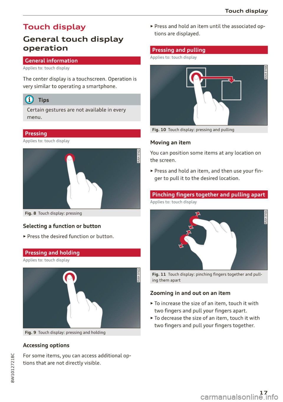
ouch displ > Press and hold an item until the associated op-
tions are displayed.
General touch display
operation eee ne
Applies to: touch display
Applies to: touch display
The center display is a touchscreen. Operation is
very similar to operating a smartphone.
@ Tips
Certain gestures are not available in every
menu.
Fig. 10 Touch display: pressing and pulling
Applies to: touch display Moving an item
You can position some items at any location on
the screen.
>» Press and hold an item, and then use your fin-
ger to pull it to the desired location.
Applies to: touch display
Fig. 8 Touch display: pressing
RAH-9164]
Selecting a function or button
> Press the desired function or button.
Applies to: touch display
Fig. 11 Touch display: pinching fingers together and pull-
ing them apart
Zooming in and out on an item
> To increase the size of an item, touch it with
two fingers and pull your fingers apart.
> To decrease the size of an item, touch it with
two fingers and pull your fingers together.
Fig. 9 Touch display: pressing and holding
Accessing options
For some items, you can access additional op-
tions that are not directly visible.
17