key AUDI A5 2008 8T / 1.G Workshop Manual
[x] Cancel search | Manufacturer: AUDI, Model Year: 2008, Model line: A5, Model: AUDI A5 2008 8T / 1.GPages: 313, PDF Size: 12.13 MB
Page 211 of 313
Towing a trailer209
Controls
Safety
Driving tips
General maintenance
Self-help
Technical data additional mirrors fitted. Both exterior mirrors should be mounted
on hinged extension brackets. Adjust the mirrors to give sufficient
vision to the rear.
Headlights
Before starting a journey, check the headlight beam settings with
the trailer hitched up. If necessary, alter the height of the headlight
beams by means of the headlight range control ⇒page 56.
Power supply
When you remove the ignition key the power supply to the trailer is
interrupted.
Removable ball joint coupling
Vehicles with a factory-fitted towing bracket are equipped with a
removable ball joint coupling. It is carried under the floor panel on
the left-hand side of the luggage compartment.
Note
We recommend having the car serviced between the normal inspec-
tion intervals if it used frequently for towing a trailer.Applies to vehicles: with towing bracketTrailer stabilisation system
Trailer stabilisation helps to reduce the risk of the vehicle
skidding when towing a trailer.When is the trailer stabilisation system activated?
Trailer stabilisation is active when the following requirements are
met:•
The ESP must NOT be switched off ⇒page 196,
•
The trailer connector must be properly secured in the vehicle
socket.
•
Vehicle speed must be higher than approx. 60 km/h.How trailer stabilisation works:
In many cases, the driver can stabilise a swaying trailer by manually
braking the vehicle.
However, if the ESP detects that the trailer is swaying and this is
affecting the towing vehicle, it will automatically brake the vehicle
to stabilise the trailer by slowing it down. The warning lamp
will
light up in the instrument cluster. If possible, do not turn the
steering wheel at this stage.
In order to warn traffic behind you, the brake lights will come on
during this automatic braking operation.
A trailer weighing less than 70% of the kerb weight of the towing
vehicle may sway quite considerably without the trailer stabilisation
system intervening. This can happen when the swaying movements
of the light-weight trailer are not or hardly passed on to the towing
vehicle and are therefore not detected by the ESP.
If the system for activating the trailer brake lights is defective, this
will be indicated in the instrument cluster display ⇒page 36, “Bulb
monitor ”.
Requirements for correct functioning of the trailer
stabilisation system
If these conditions are not met in full, the trailer stabilisation system
will only intervene to a limited extent or not at all ⇒.
•
The electrical connection between the towing vehicle and the
trailer must be functioning correctly, without any defects.
•
The load on the trailer must be properly secured.
•
The tyre pressures on both the vehicle and the trailer must be
adapted to the load that is being carried.
•
Where possible, operate the trailer with the maximum permitted
draw bar weight.
•
The trailer overrun brake must be set correctly. This is important
to ensure that the trailer can be braked correctly, to avoid the vehicle
and trailer “jack-knifing” and to prevent excess braking of the trailer.
document_0900452a8179700c.book Seite 209 Donnerstag, 22. März 2007 10:19 10
Page 215 of 313
Towing a trailer213
Controls
Safety
Driving tips
General maintenance
Self-help
Technical data
– Also check the shaft section of the ball joint and its asso-
ciated mechanical parts to make sure they are clean and
undamaged.Continued ⇒page 213, “Fitting the ball joint (step 2)”.
WARNING
It is important to keep the mounting fixture clean. Otherwise the
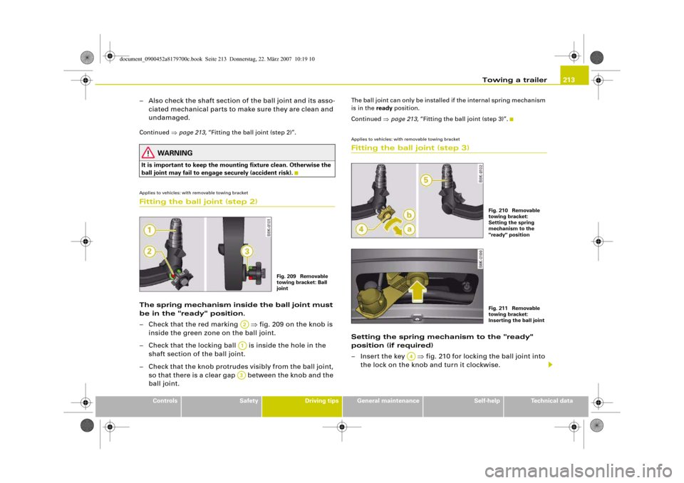
ball joint may fail to engage securely (accident risk).Applies to vehicles: with removable towing bracketFitting the ball joint (step 2)The spring mechanism inside the ball joint must
be in the "ready" position.
– Check that the red marking ⇒fig. 209 on the knob is
inside the green zone on the ball joint.
– Check that the locking ball is inside the hole in the
shaft section of the ball joint.
– Check that the knob protrudes visibly from the ball joint,
so that there is a clear gap between the knob and the
ball joint.
The ball joint can only be installed if the internal spring mechanism
is in the ready position.
Continued ⇒page 213, “Fitting the ball joint (step 3)”.Applies to vehicles: with removable towing bracketFitting the ball joint (step 3)Setting the spring mechanism to the "ready"
position (if required)
– Insert the key ⇒fig. 210 for locking the ball joint into
the lock on the knob and turn it clockwise.
Fig. 209 Removable
towing bracket: Ball
joint
A2A1A3
Fig. 210 Removable
towing bracket:
Setting the spring
mechanism to the
"ready" positionFig. 211 Removable
towing bracket:
Inserting the ball joint
A4
document_0900452a8179700c.book Seite 213 Donnerstag, 22. März 2007 10:19 10
Page 216 of 313
Towing a trailer 214
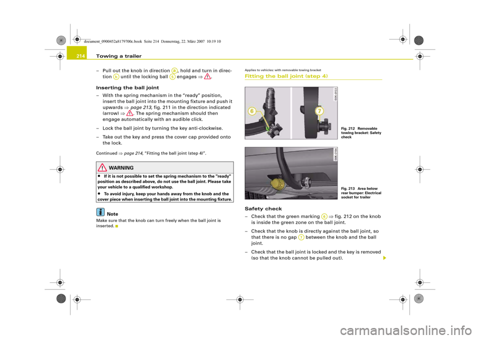
– Pull out the knob in direction , hold and turn in direc-
tion until the locking ball engages ⇒.
Inserting the ball joint
– With the spring mechanism in the “ready” position,
insert the ball joint into the mounting fixture and push it
upwards ⇒page 213, fig. 211 in the direction indicated
(arrow) ⇒. The spring mechanism should then
engage automatically with an audible click.
– Lock the ball joint by turning the key anti-clockwise.
– Take out the key and press the cover cap provided onto
the lock.Continued ⇒page 214, “Fitting the ball joint (step 4)”.
WARNING
•
If it is not possible to set the spring mechanism to the "ready"
position as described above, do not use the ball joint. Please take
your vehicle to a qualified workshop.
•
To avoid injury, keep your hands away from the knob and the
cover piece when inserting the ball joint into the mounting fixture.Note
Make sure that the knob can turn freely when the ball joint is
inserted.
Applies to vehicles: with removable towing bracketFitting the ball joint (step 4)Safety check
– Check that the green marking ⇒fig. 212 on the knob
is inside the green zone on the ball joint.
– Check that the knob is directly against the ball joint, so
that there is no gap between the knob and the ball
joint.
– Check that the ball joint is locked and the key is removed
(so that the knob cannot be pulled out).
Aa
Ab
A5
Fig. 212 Removable
towing bracket: Safety
checkFig. 213 Area below
rear bumper: Electrical
socket for trailer
A6
A7
document_0900452a8179700c.book Seite 214 Donnerstag, 22. März 2007 10:19 10
Page 217 of 313
Towing a trailer215
Controls
Safety
Driving tips
General maintenance
Self-help
Technical data
– Check that the ball joint fits tightly in the mounting
fixture (try moving it about to check).
Electrical socket for trailer
– The cable of the towing bracket can be connected to the
socket ⇒page 214, fig. 213.If the safety check is not satisfactory, the ball joint must be fitted
again properly.
WARNING
To avoid accidents, the ball joint must meet all the safety require-
ments listed in the safety check. The towing bracket must not be
used if any one of these requirements is not met. If this is the case,
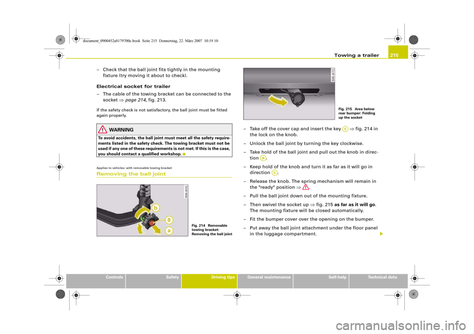
you should contact a qualified workshop.Applies to vehicles: with removable towing bracketRemoving the ball joint
– Take off the cover cap and insert the key ⇒fig. 214 in
the lock on the knob.
– Unlock the ball joint by turning the key clockwise.
– Take hold of the ball joint and pull out the knob in direc-
tion .
– Keep hold of the knob and turn it as far as it will go in
direction .
– Release the knob. The spring mechanism will remain in
the "ready" position ⇒.
– Pull the ball joint down out of the mounting fixture.
– Then swivel the socket up ⇒fig. 215 as far as it will go.
The mounting fixture will be closed automatically.
– Fit the bumper cover over the opening on the bumper.
– Put away the ball joint attachment under the floor panel
in the luggage compartment.
Fig. 214 Removable
towing bracket:
Removing the ball joint
Fig. 215 Area below
rear bumper: Folding
up the socketA8
Aa
Ab
document_0900452a8179700c.book Seite 215 Donnerstag, 22. März 2007 10:19 10
Page 233 of 313
Checking and topping up fluids231
Controls
Safety
Driving tips
General maintenance
Self-help
Technical data
Working on components in the engine compartment
Extra caution is necessary when working on components
in the engine compartment.Always be aware of the danger of injury and scalding as well as the
risk of accident or fire when working in the engine compartment
(e.g. when checking and refilling fluids). Always observe the warn-
ings listed below and follow all normal safety precautions. The
engine compartment of any motor vehicle is a potentially
hazardous area. ⇒.
WARNING
•
Switch off the engine.
•
Remove the ignition key.
•
Apply the parking brake.
•
Put the gear lever in neutral or selector in P.
•
Wait for the engine to cool down.
•
Keep children away from engine compartment.
•
Never spill fluids on hot engine components. These fluids can
cause a fire (e.g. radiator anti-freeze).
•
Take care not to cause short circuits in the electrical system,
especially when working on the battery.
•
Do not touch the radiator fan when the engine is hot. The fan
may start running suddenly.
•
Do not unscrew the cap on the expansion tank when the engine
is hot. The cooling system is under pressure.
•
Protect face, hands and arms by covering the cap with a large,
thick rag to protect against escaping coolant and steam.
•
If any tests have to be performed with the engine running,
there is an extra safety risk from the rotating parts, such as the
drive belts, alternator and radiator fan, etc., and from the high-
voltage ignition system.
•
Vehicles with automatic gearbox: Never open the throttle inad-
vertently (for instance by hand from the engine compartment) if a
gear is engaged while the vehicle is stationary with the engine
running. The vehicle could otherwise start moving immediately
and possibly cause an accident.
•
Observe the following additional warnings if work on the fuel
system or the electrical system is necessary:
−Always disconnect the battery.
−Do not smoke.
−Never work near naked flames.
−Always keep an approved fire extinguisher immediately
available.Caution
When topping up fluids make sure the correct fluid is put into the
correct filler opening. This can otherwise cause serious malfunc-
tions or engine damage.
For the sake of the environment
Inspect the ground underneath your vehicle regularly so that any
leaks are detected at an early stage. If you find oil spots or other
fluids, have your vehicle inspected by a qualified workshop.
Note
On right-hand drive vehicles* some of the containers/ reservoirs
mentioned below are located on the other side of the engine
compartment.
WARNING (continued)
document_0900452a8179700c.book Seite 231 Donnerstag, 22. März 2007 10:19 10
Page 241 of 313
Checking and topping up fluids239
Controls
Safety
Driving tips
General maintenance
Self-help
Technical data
For the sake of the environment
If the fluid has to be drained out of the brake system, use an appro-
priate container to catch the used brake fluid and dispose of it in the
proper manner.BatteryGeneral notes
All work on batteries requires specialist knowledge.The battery is virtually maintenance-free. It is checked as part of the
Inspection Service.
We recommend that you replace a battery once it is older than 5
years.
When an airbag is triggered, the battery will, under certain circum-
stances, be disconnected from the on-board power supply for
safety reasons ⇒ in “General notes on airbag system” on
page 176.
Disconnecting the battery
If the battery is disconnected, some of the vehicle's functions will
become inoperative (e.g. electric windows). These functions will
require resetting after the battery is reconnected. For this reason,
the battery should only be disconnected from the vehicle's electrical
system when absolutely necessary.
If the vehicle is not used for long periods
If you do not drive your vehicle for a period of several days or weeks,
the power management will gradually shut off the on-board
systems one by one, or reduce the amount of current they are using.
This limits the amount of power consumed and helps to ensure reli-
able starting even after a long period ⇒page 202.Please note that certain convenience features, such as the Audi
advanced key*, the remote control key or the electrical seat adjust-
ment may not be available when you unlock the vehicle. These func-
tions will be restored when you switch on the ignition and start the
engine.
Winter conditions
At low temperatures the battery has to work very hard. It also
provides only a fraction of the starting power it has at normal
temperatures.
For this reason, we recommend having the battery checked and
charged if necessary before the start of winter ⇒page 241.
WARNING
•
All work on batteries requires specialist knowledge. For queries
regarding the vehicle battery please contact an Audi dealership or
other qualified workshop (risk of chemical burns / risk of explo-
sion).
•
The battery must not be opened. Do not attempt to make any
changes to the electrolyte level of the battery. Otherwise, there is
a risk that a mixture of oxygen and hydrogen gas can accumulate
and cause an explosion.Note
If the vehicle is to be left standing for a period of several weeks at
extremely low temperatures, the battery should be removed from
the vehicle. This ensures that it cannot “freeze up” and be
damaged.
document_0900452a8179700c.book Seite 239 Donnerstag, 22. März 2007 10:19 10
Page 242 of 313
Checking and topping up fluids 240Important safety warnings for handling a car battery
All work on batteries requires specialist knowledge.The vehicle battery is located under the floor panel in the luggage
compartment.
WARNING
Always be aware of the danger of injury and chemical burns as
well as the risk of accident or fire when working on the battery and
the electrical system.•
Wear safety glasses. Do not allow acid or lead particles to come
into contact with eyes, skin or clothing.
•
Battery acid is extremely corrosive. Wear protective gloves and
safety glasses. Do not tilt the battery - acid can leak out of the
vapour vent. If electrolyte should splash into the eyes rinse at once
for several minutes using clear water. Then seek medical care
immediately. Neutralize any acid splashes on the skin or clothing
with soap solution, and rinse off with plenty of water. If acid is
swallowed by mistake, consult a doctor immediately.
•
Keep open flames, sparks, uncovered lights and lit cigarettes
away from battery. Avoid sparks (including those from static charges) when handling cables and electrical equipment. Never
cross the battery poles. The resulting high-energy sparks can
cause injury.
•
A highly explosive mixture of gases is given off when the
battery is under charge. Only charge battery in a well ventilated
area.
•
Keep children away from the battery and battery acid.
•
Switch off all electrical equipment before starting any work on
the vehicle electrical system. Remove the ignition key. The minus
cable of the battery must be disconnected. When changing a light
bulb, it is sufficient to only turn off the light.
•
Before disconnecting the battery, turn off the anti-theft
system! Otherwise, the alarm will sound.
•
When disconnecting the battery from the vehicle's electrical
system, first disconnect the minus cable and then the plus cable.
•
Before reconnecting the battery, turn off all electrical equip-
ment. First connect the plus cable, then the minus cable. The
battery cables must not be connected to the wrong battery poles
- serious risk of cable fire.
•
Never charge a frozen or thawed out battery - risk of explosion
and chemical burns! A battery must be replaced once it has been
frozen. When it is discharged the battery can freeze at tempera-
tures around 0°C.
•
Make sure that the vapour hose is always attached to the
battery.
•
Never use a damaged battery - risk of explosion! Replace a
damaged battery immediately.Caution
•
Never disconnect the car's battery with the engine running or
with the ignition turned on, otherwise the electrical system or elec-
trical components will be damaged.
Wear safety glasses!
Battery acid is extremely corrosive. Wear protec-
tive gloves and safety glasses.
Keep open flames, sparks, uncovered lights and
lit cigarettes away from battery!
A highly explosive mixture of gases is given off
when the battery is under charge!
Keep children away from the battery and battery
acid.
WARNING (continued)
document_0900452a8179700c.book Seite 240 Donnerstag, 22. März 2007 10:19 10
Page 243 of 313
Checking and topping up fluids241
Controls
Safety
Driving tips
General maintenance
Self-help
Technical data
•
Do not expose the battery to direct sunlight over a long period of
time, as the intense ultraviolet radiation can affect the battery
housing.
•
If the car is left standing for long periods, protect the battery
from extreme cold temperature so that it does not “freeze up” and
become damaged.
Charging the battery
Terminals for charging the battery are fitted in the engine
compartment.– Note the warnings ⇒ in “Important safety warnings
for handling a car battery” on page 240 and ⇒.
– Switch off all electrical equipment. Remove the ignition
key.
– Open the bonnet ⇒page 230.
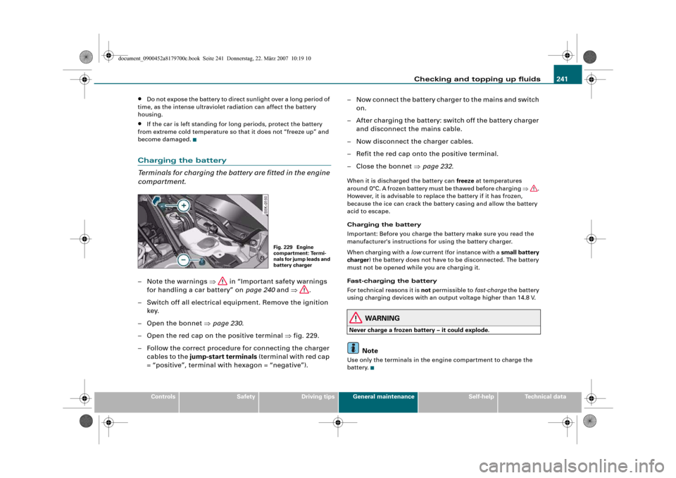
– Open the red cap on the positive terminal ⇒fig. 229.
– Follow the correct procedure for connecting the charger
cables to the jump-start terminals (terminal with red cap
= “positive”, terminal with hexagon = “negative”).– Now connect the battery charger to the mains and switch
on.
– After charging the battery: switch off the battery charger
and disconnect the mains cable.
– Now disconnect the charger cables.
– Refit the red cap onto the positive terminal.
– Close the bonnet ⇒page 232.
When it is discharged the battery can freeze at temperatures
around 0°C. A frozen battery must be thawed before charging ⇒.
However, it is advisable to replace the battery if it has frozen,
because the ice can crack the battery casing and allow the battery
acid to escape.
Charging the battery
Important: Before you charge the battery make sure you read the
manufacturer's instructions for using the battery charger.
When charging with a low current (for instance with a small battery
charger) the battery does not have to be disconnected. The battery
must not be opened while you are charging it.
Fast-charging the battery
For technical reasons it is not permissible to fast-charge the battery
using charging devices with an output voltage higher than 14.8 V.
WARNING
Never charge a frozen battery – it could explode.
Note
Use only the terminals in the engine compartment to charge the
battery.
Fig. 229 Engine
compartment: Termi-
nals for jump leads and
battery charger
document_0900452a8179700c.book Seite 241 Donnerstag, 22. März 2007 10:19 10
Page 279 of 313
Fuses and bulbs277
Controls
Safety
Driving tips
General maintenance
Self-help
Technical data
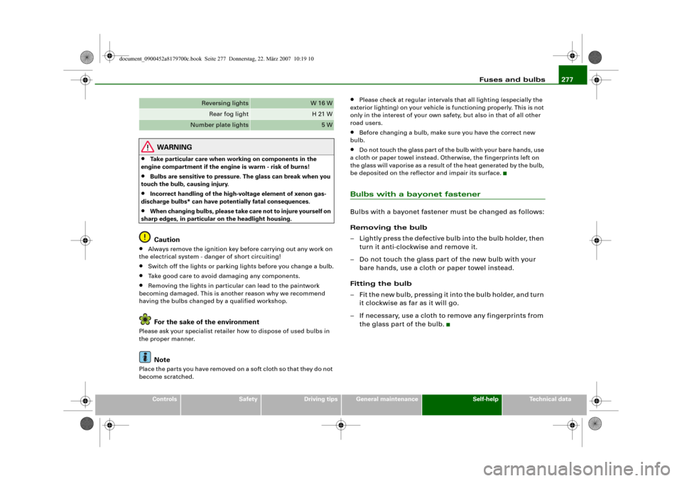
WARNING
•
Take particular care when working on components in the
engine compartment if the engine is warm - risk of burns!
•
Bulbs are sensitive to pressure. The glass can break when you
touch the bulb, causing injury.
•
Incorrect handling of the high-voltage element of xenon gas-
discharge bulbs* can have potentially fatal consequences.
•
When changing bulbs, please take care not to injure yourself on
sharp edges, in particular on the headlight housing.Caution
•
Always remove the ignition key before carrying out any work on
the electrical system - danger of short circuiting!
•
Switch off the lights or parking lights before you change a bulb.
•
Take good care to avoid damaging any components.
•
Removing the lights in particular can lead to the paintwork
becoming damaged. This is another reason why we recommend
having the bulbs changed by a qualified workshop.For the sake of the environment
Please ask your specialist retailer how to dispose of used bulbs in
the proper manner.
Note
Place the parts you have removed on a soft cloth so that they do not
become scratched.
•
Please check at regular intervals that all lighting (especially the
exterior lighting) on your vehicle is functioning properly. This is not
only in the interest of your own safety, but also in that of all other
road users.
•
Before changing a bulb, make sure you have the correct new
bulb.
•
Do not touch the glass part of the bulb with your bare hands, use
a cloth or paper towel instead. Otherwise, the fingerprints left on
the glass will vaporise as a result of the heat generated by the bulb,
be deposited on the reflector and impair its surface.
Bulbs with a bayonet fastenerBulbs with a bayonet fastener must be changed as follows:
Removing the bulb
– Lightly press the defective bulb into the bulb holder, then
turn it anti-clockwise and remove it.
– Do not touch the glass part of the new bulb with your
bare hands, use a cloth or paper towel instead.
Fitting the bulb
– Fit the new bulb, pressing it into the bulb holder, and turn
it clockwise as far as it will go.
– If necessary, use a cloth to remove any fingerprints from
the glass part of the bulb.
Reversing lights
W 16 W
Rear fog light
H 21 W
Number plate lights
5 W
document_0900452a8179700c.book Seite 277 Donnerstag, 22. März 2007 10:19 10
Page 304 of 313
Index 302AABS
SeeAnti-lock brake system . . . . . . . . . 18
AC mode . . . . . . . . . . . . . . . . . . . . . . . 98, 107
Acceleration figures
SeePerformance, weights and
dimensions . . . . . . . . . . . . . . . . . . . . 295
Accessories . . . . . . . . . . . . . . . . . . . . . . . . 250
Trailer . . . . . . . . . . . . . . . . . . . . . . . . . . 211
Adapter for anti-theft wheel bolts . . . . . 264
adaptive light . . . . . . . . . . . . . . . . . . . . . . . 58
Defective . . . . . . . . . . . . . . . . . . . . . . . . 37
advanced key
Locking and unlocking the vehicle . . . 45
START ENGINE STOP button . . . . . . . 118
Starting the engine . . . . . . . . . . . . . . . 118
Switching on the ignition . . . . . . . . . . 118
Air conditioner . . . . . . . . . . . . . . . . . . 93, 101
AC mode . . . . . . . . . . . . . . . . . . . . . . . . . 98
See alsoDeluxe automatic air conditioner
93
Air recirculation mode
Deluxe automatic air conditioner . . . . 97
Deluxe automatic air conditioner plus . . .
106
Airbag . . . . . . . . . . . . . . . . . . . . . . . . . . . . 176
Deactivating . . . . . . . . . . . . . . . . . . . . . 183
Front airbags . . . . . . . . . . . . . . . . . . . . 178
Head-protection airbag . . . . . . . . . . . 181
Key-operated switch for front passenger's
airbag . . . . . . . . . . . . . . . . . . . . . . . . 183
Side airbags . . . . . . . . . . . . . . . . . . . . . 180Triggering . . . . . . . . . . . . . . . . . . . . . . 177
Warning lamp . . . . . . . . . . . . . . . . . . . . 16
Alterations to the vehicle . . . . . . . . . . . . . 250
Alternator
Fault . . . . . . . . . . . . . . . . . . . . . . . . . . . . 31
Anti-dazzle interior mirror . . . . . . . . . . . . . 66
Anti-freeze additive . . . . . . . . . . . . . . . . . 235
Anti-knock properties of petrol . . . . . . . . 227
Anti-lock brake system
How the system works . . . . . . . . . . . . 197
Warning lamp . . . . . . . . . . . . . . . . . . . . 18
Anti-theft alarm . . . . . . . . . . . . . . . . . . . . . . 42
Interior monitor . . . . . . . . . . . . . . . . . . . 47
Tow-away protection . . . . . . . . . . . . . . 47
Anti-theft wheel bolts . . . . . . . . . . . . . . . . 264
Armrest (front)
Adjusting . . . . . . . . . . . . . . . . . . . . . . . . 77
Storage compartment . . . . . . . . . . . . . 77
Ashtrays
Front . . . . . . . . . . . . . . . . . . . . . . . . . . . . 86
Rear . . . . . . . . . . . . . . . . . . . . . . . . . . . . . 87
Audi hold assist . . . . . . . . . . . . . . . . . . . . 124
Warning lamp . . . . . . . . . . . . . . . . . . . . 18
Auto Lock . . . . . . . . . . . . . . . . . . . . . . . . . . . 42
Auto-check control . . . . . . . . . . . . . . . . . . . 29
Automatic air conditioner plus
SeeDeluxe automatic air conditioner plus
101
Automatic gearbox
Manual release (multitronic®) . . . . . . 136
multitronic® . . . . . . . . . . . . . . . . . . . . 130
Safety interlock for ignition key . . . . 116Selector lever positions (multitronic®) . . .
131
Steering wheel with tiptronic controls . . .
135
Automatic headlight control . . . . . . . . . . . 54
Auxiliary heating
Deluxe automatic air conditioner plus . . .
111
Description . . . . . . . . . . . . . . . . . . . . . . 111
Remote control . . . . . . . . . . . . . . . . . . 114
Running time . . . . . . . . . . . . . . . . . . . . 113
Switching on/off immediately . . . . . . 112
Timer . . . . . . . . . . . . . . . . . . . . . . . . . . . 112
Average fuel consumption . . . . . . . . . . . . . 25
Average speed . . . . . . . . . . . . . . . . . . . . . . . 25
Axle weights
SeePerformance, weights and
dimensions . . . . . . . . . . . . . . . . . . . . 295
BBattery
Charging . . . . . . . . . . . . . . . . . . . . . . . . 241
Low charge . . . . . . . . . . . . . . . . . . . . . . 202
Power level . . . . . . . . . . . . . . . . . . . . . . 202
Power management . . . . . . . . . . . . . . 202
Replacing . . . . . . . . . . . . . . . . . . . . . . . 242
Winter conditions . . . . . . . . . . . . . . . . 239
Battery power . . . . . . . . . . . . . . . . . . . . . . . 36
Bayonet fastener
Bulb . . . . . . . . . . . . . . . . . . . . . . . . . . . . 277
Bulb holder . . . . . . . . . . . . . . . . . . . . . . 278
Belt tensioners . . . . . . . . . . . . . . . . . . . . . 175
document_0900452a8179700c.book Seite 302 Donnerstag, 22. März 2007 10:19 10