cruise control AUDI A5 2015 Owner´s Manual
[x] Cancel search | Manufacturer: AUDI, Model Year: 2015, Model line: A5, Model: AUDI A5 2015Pages: 264, PDF Size: 66.83 MB
Page 4 of 264
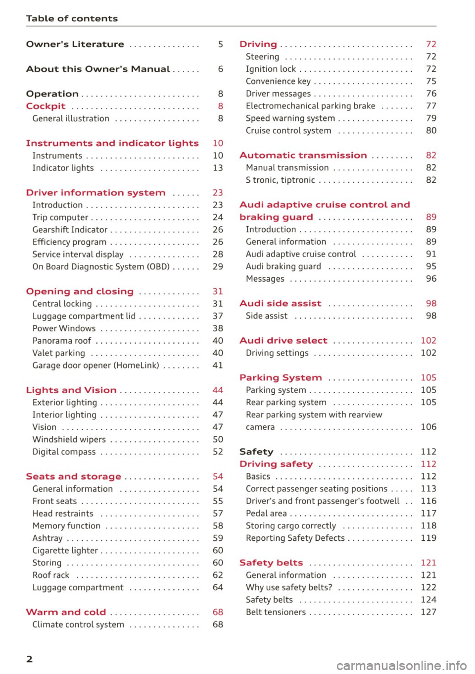
Table of contents
Owner's Literature
About this Owner's Manual ... .. .
Operation ....... ........... .. .. .. .
Cockpit ... .. ............... .. .. .. .
Gene ral illus tra tion . ..... ... .. .. .. .. . 5
6
8
8
8
Instrument
s and indicator lights 10
Instruments . . . . . . . . . . . . . . . . . . . . . . . . 10
Indicator ligh ts . . . . . . . . . . . . . . . . . . . . . 1 3
Driver information system . . . . . . 23
I n troduct ion . . . . . . . . . . . . . . . . . . . . . . . . 23
Trip computer . . . . . . . . . . . . . . . . . . . . . . .
24
Gearshift Indicator . . . . . . . . . . . . . . . . . . . 26
E fficiency program . . . . . . . . . . . . . . . . . . . 26
Service interval disp lay . . . . . . . . . . . . . . . 28
O n Board Diag nostic System (OBD) . . . . . . 29
Open ing and closing . . . . . . . . . . . . . 31
Centra l locking . . . . . . . . . . . . . . . . . . . . . . 31
Luggage compartment lid . . . . . . . . . . . . . 37
Powe r W indows . . . . . . . . . . . . . . . . . . . . . 38
P anorama roof . . . . . . . . . . . . . . . . . . . . . . 40
Va let par king . . . . . . . . . . . . . . . . . . . . . . . 40
G arage door ope ner (Home Link) . . . . . . . .
4 1
Lights and Vision . . . . . . . . . . . . . . . . . 44
E xte rior ligh ting . . . . . . . . . . . . . . . . . . . . .
4 4
Interior lighting . . . . . . . . . . . . . . . . . . . . . 47
V1s1on ... .... ... .. .. ..... ... .. .. .. .
Windshield wipers .. ..... ... .. .. .. .. .
Dig ita l compass ... ........... .. .. .. . 4
7
so
52
Seats and storage . . . . . . . . . . . . . . . . 54
Gene ral i nfo rmation . . . . . . . . . . . . . . . . . 54
Front seats . . . . . . . . . . . . . . . . . . . . . . . . . 55
H ead restraints . . . . . . . . . . . . . . . . . . . . . 57
Memory funct ion . . . . . . . . . . . . . . . . . . . .
58
Ashtray . . . . . . . . . . . . . . . . . . . . . . . . . . . . 59
Ciga rette lig hte r. . . . . . . . . . . . . . . . . . . . .
60
Sto ring . . . . . . . . . . . . . . . . . . . . . . . . . . . . 60
Roof rac k . . . . . . . . . . . . . . . . . . . . . . . . . . 6 2
L uggage compartmen t . . . . . . . . . . . . . . . 64
Warm and cold . . . . . . . . . . . . . . . . . . . 68
Climate con tro l sys tem . . . . . . . . . . . . . . . 6 8
2
Driving .... . .... .. .. ... . .. .... ... . .
Steering . ... .... .. .. .. .. .. .... ... . .
72
72
Ign it ion loc k . . . . . . . . . . . . . . . . . . . . . . . . 72
Convenience key . . . . . . . . . . . . . . . . . . . . . 75
Driver messages . . . . . . . . . . . . . . . . . . . . . 76
E lectromechan ical pa rking brake . . . . . . .
77
Speed warning system . . . . . . . . . . . . . . . . 79
Cru ise cont ro l system . . . . . . . . . . . . . . . .
80
Automatic transmission . . . . . . . . . 82
Manua l transm ission . . . . . . . . . . . . . . . . . 82
5 tronic , tiptronic . . . . . . . . . . . . . . . . . . . . 82
Audi adaptive cruise control and
braking guard . . . . . . . . . . . . . . . . . . . .
89
Introduc tion . . . . . . . . . . . . . . . . . . . . . . . . 89
Gener al informa tion . . . . . . . . . . . . . . . . . 89
Audi adaptive cruise contro l . . . . . . . . . . .
91
Audi braking guard . . . . . . . . . . . . . . . . . . 95
Messages . . . . . . . . . . . . . . . . . . . . . . . . . . 96
Audi side assi st . . . . . . . . . . . . . . . . . . 98
Side assist . . . . . . . . . . . . . . . . . . . . . . . . . 98
Audi drive select . . . . . . . . . . . . . . . . . 102
Driving settings . . . . . . . . . . . . . . . . . . . . . 102
Parking System . . . . . . . . . . . . . . . . . . 105
Pa rking system . . . . . . . . . . . . . . . . . . . . . . 105
Rear par king system . . . . . . . . . . . . . . . . . 105
Rear parking system w ith rearview
camera
106
Safety 112
Driving safety . . . . . . . . . . . . . . . . . . . . 112
Bas ics . . . . . . . . . . . . . . . . . . . . . . . . . . . . . 112
Correc t passenger seating positions . . . . . 113
D river 's and front passenger 's footwell . . 116
Pedal area . . . . . . . . . . . . . . . . . . . . . . . . . . 117
Stor ing cargo co rrectly . . . . . . . . . . . . . . . 118
Repo rting Sa fe ty Defe cts.......... .. .. 119
Safety belts . . . . . . . . . . . . . . . . . . . . . . 121
General informa tion . . . . . . . . . . . . . . . . . 1 2 1
Why use safety bel ts? . . . . . . . . . . . . . . . . 122
Safety be lts . . . . . . . . . . . . . . . . . . . . . . . . 12 4
Be lt tensioners . . . . . . . . . . . . . . . . . . . . . . 127
Page 11 of 264
M N
i? co ,...., \!) ..,.,
N l/'I ,....,
CD
@
®
©
®
®
(j)
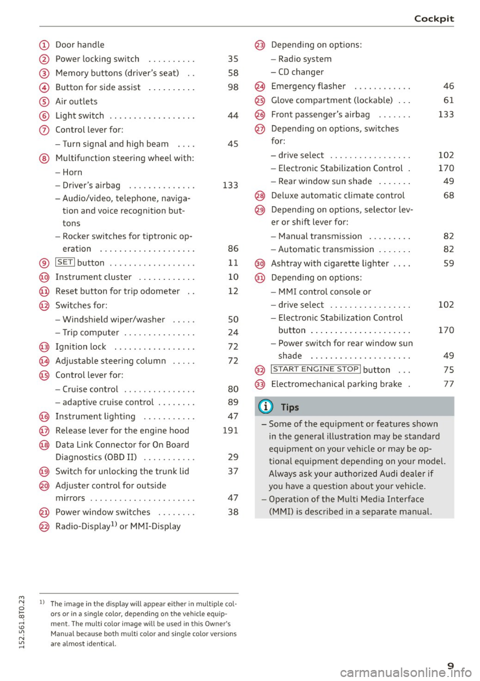
Door handle
Power locking swi tch
Memory buttons (driver's seat) . .
Button for side assist
A ir outlets
Light switch
Control lever for:
- Turn signal and high beam
@ Multifunction steering wheel with :
- Horn
- Driver' s airbag ....... .. .. .. .
- Audio/video , telephone, naviga-
tion and voice recognition but
tons
- Rocker switches for tiptronic op-
eration ............. .... .. .
® IS ETI button ................. .
@ Instrument cluster ........ ... .
@ Reset button for trip odometer
@ Switches for:
- Windshield wiper/washer
- Trip computer .............. .
Ignition lock . .......... ... .. .
Adjustable steering column
Control lever for:
- Cruise control ............ .. .
- adaptive cruise control ..... .. .
@ Instrument lighting ...... .. .. .
@ Release lever for the engine hood
@ Data Link Connector for On Board
Diagnostics (OBD II) ..... ... .. .
@ Switch for unlocking the trunk lid
@ Adjuster control for outside
mirrors ................ ... .. .
@ Power window switches . .. .. .. .
@ Radio-Display1l or MMI-Display
35
58
98
44
45
133
86
11
10
12
so
24
72
72
80
89
47
191
29
37
47 38
l) Th e im age in t he d ispl ay will app ea r e ither in mult ipl e col
or s or in a s ingle color, depending on the vehicle e quip
m ent. The mul ti color image w ill b e used in this Ow ne r's
Man ual bec ause both multi co lo r an d single color vers io n s
are a lmo st i de nti cal.
Cockpit
Depending on options:
- Radio system
- CD changer
Emergency flasher
Glove compartment (lockable) .. .
F ront p assenger's airbag . .. .. . .
Depend ing on options, switches
for:
- drive select .. ........... .. . .
- Electronic Stabilization Control .
- Rear window sun shade ...... .
@ Deluxe automa tic climate control
@) Depend ing on options, selector lev
er or shift lever for:
- Manual transmission ........ .
- Automatic transmission ...... .
@ Ashtray with cigarette lighter
@ Depend ing on options:
- MM I control console or
- drive select . ............... .
- Electron ic Stabilization Control
button . ..... .............. .
- Power switch for rear window sun
shade .... .. .............. .
@ I START ENG IN E STOPI button . . .
@) Electromechanical parking brake
(D Tips
46
61
133
102
170
49
68
82
82
59
102
170
49
75
77
- Some of the equipment or features shown
in the general illustration may be standard
equipment on your veh icle or may be op
tional equ ipment depending on your model.
Always ask your author ized Audi dealer if
you have a question about your vehicle.
- Operation of the Multi Media Interface
(MMI) is described in a separate manua l.
9
Page 15 of 264
M N
i? co ,...., \!) 1.1"1
N 1.1"1 ,....,
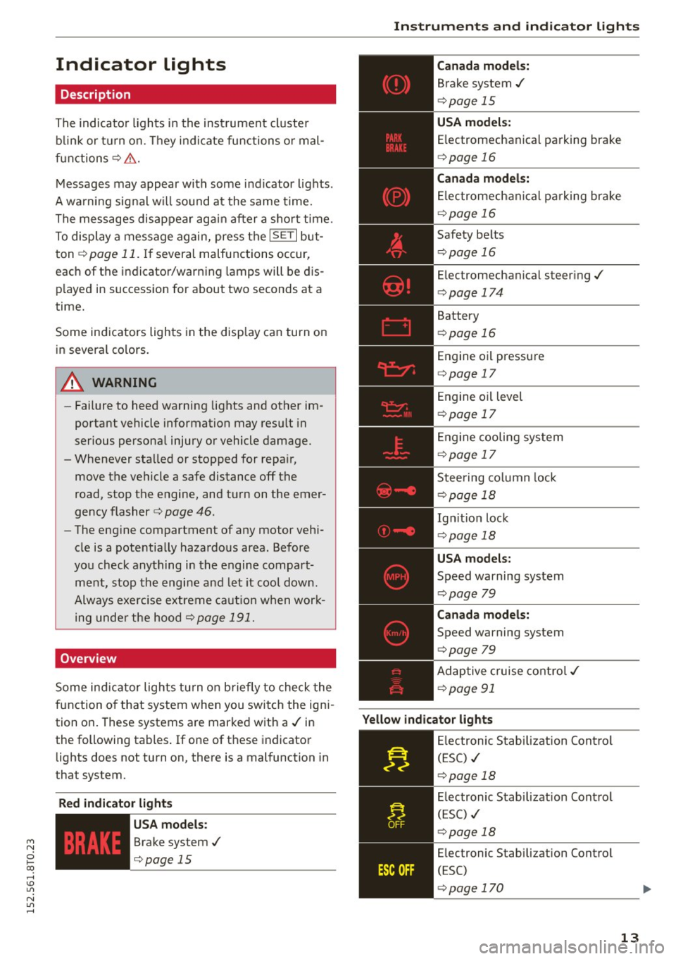
Indicator lights
Description
The indicator lights in the instrument cluster
blink or turn on. They indicate functions or mal
functions¢ &.
Messages may appear with some indicator lights .
A warning signal will sound at the same time.
The messages disappear again after a short time.
To display a message again, press the
I SE TI but
ton ¢
page 11. If several malfunctions occur,
each of the indicator/warning lamps will be dis
p layed in succession for about two seconds at a
time.
Some indicators lights in the display can turn on
in several colors.
8_ WARNING
- Failure to heed warning lights and other im
portant vehicle information may resu lt in
serious personal injury or vehicle damage.
- Whenever sta lled or stopped for repa ir,
move the vehicle a safe distance off the
road, stop the engine, and turn on the emer
gency flasher ¢
page 46.
-The engine compartment of any motor vehi
cle is a potentially hazardous area. Before
you check anything in the engine compart
ment, stop the engine and let it cool down.
Always exercise extreme caution when work
ing under the hood ¢
page 191.
Overview
Some ind icator lights turn on briefly to check the
function of that system when you switch the igni
tion on . These systems are marked with a./ in
the following tables .
If one of these indicator
lights does not turn on, there is a malfunction in
that system.
Red indicator light s
--------------
US A models:
Brake system./
¢page 15
Instruments and indicator lights
Canada models:
Brake system./
¢page 15
USA models:
Electromechanical parking brake
¢ page 16
Canada models:
Electromechanical parking brake
¢ page 16
Safety belts
¢page 16
Electromechanical steering./
¢page 174
Battery
¢page 16
Engine oil pressure
¢page 17
Engine oil level
¢page 17
Engine cooling system
¢page 17
Steering column lock
¢page 18
Ign it ion lock
¢ page 18
USA models:
Speed warning system
¢page 79
Canad a models:
Speed warning system
¢page 79
Adaptive cruise control./
¢page 91
Yellow indicator lights
--------------
Electronic Stabilization Contro l
(ESC) ./
¢page 18
Electronic Stabilization Contro l
(ESC) ./
¢page 18
Electronic Stabilization Control
(ESC)
¢page 170
13
Page 16 of 264
Instruments and indicator lights
TPMS
-~--
14
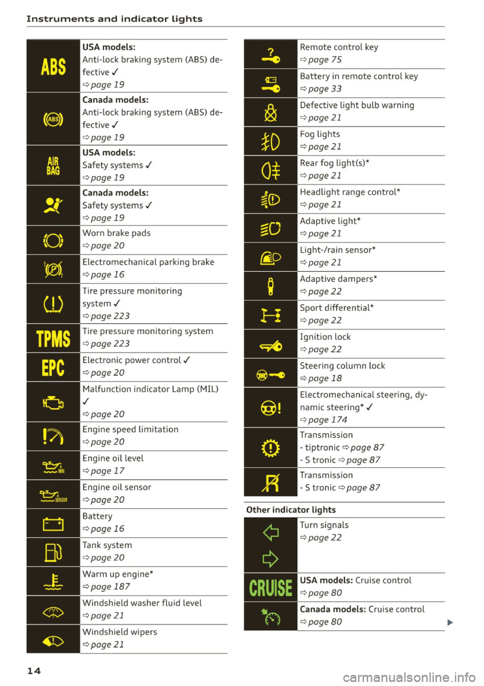
USA m odel s:
Anti-loc k braking system (ABS) de
fective,/
¢ page 19
Canada mod els :
Anti-lock braking system (ABS) de
fective,/
¢ page 19
USA models :
Safety systems./
¢page 19
Canada model s:
Safety systems ./
¢page 19
Worn brake pads
¢ page20
Elect romechanical parking b rake
¢page 16
Tire pressure monitoring
system,/
¢ page 223
Tire pressure monitoring system
¢page223
Electronic power control./
¢page20
Malf unct ion ind icator Lamp (MIL)
,I
c::>page 20
Engine speed limitat ion
c::> page20
Engine oil level
c::> page 17
Engine oil sensor
c::>page20
Battery
c::>page 16
Tank system
c::>page20
Warm up engine*
¢page 187
Windshield washe r flu id leve l
¢page 21
Windshield wipers
¢page 21
Remote cont ro l key
¢ page 75
Battery in remote control key
¢page 33
Defect ive light bulb wa rning
<=> page 21
Fog lights
¢page 21
Rear fog lig ht(s)*
c> page 21
Headlight range control*
c>page 21
Adaptive light*
c>page 21
Light-/rain sensor*
c>page 21
Adaptive dampers*
c>page22
Sport d ifferential *
<=>page22
Ig nition lock
c>page22
Steering co lumn lock
¢ page 18
Elec tromechanical s teer ing, dy
nam ic stee ring* ,/
c>page 174
Transmission
- tiptronic
c> page 87
-S tronic c::> page 87
Transmission
-5 tronic
<=> page 87
Other indicator light s
~--==------------Turn signals
<=>page22
USA mod els: Cruise cont rol
c> page80
Canada mod els : Cru ise contro l
c>page 80
Page 17 of 264
M N
i? co ,...., \!) 1.1'1
N 1.1'1 ,....,
Adaptive cruise control*
c:>page 91
Adaptive cruise control*
c:>page 91
High beam
c:>page45
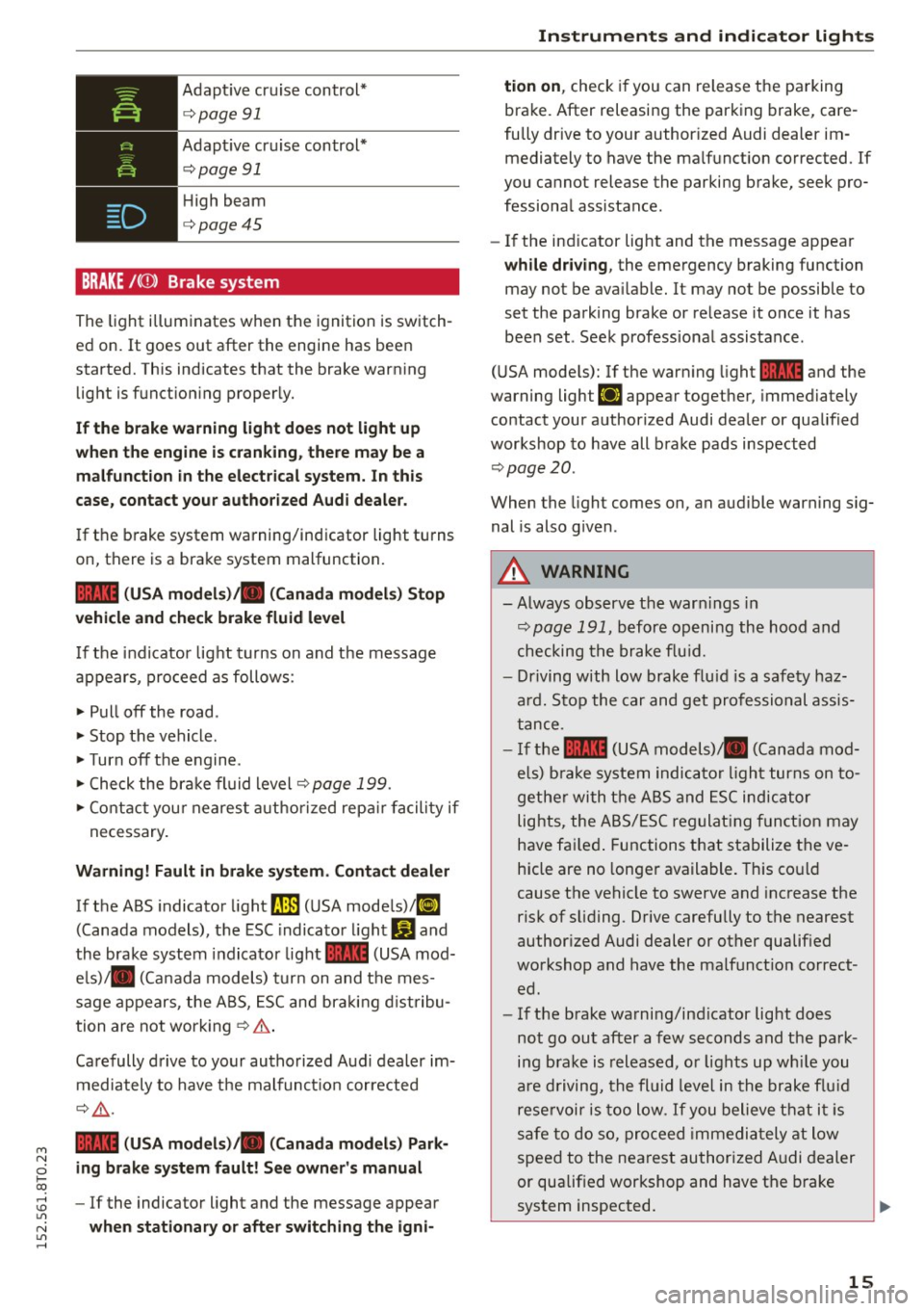
BRAKE /((J) ) Brake system
The light illuminates when the ignition is switch
ed on. It goes out after the engine has been
started. This indicates that the brake warning light is functioning properly.
If the brake warning light does not light up
when the engine is cranking, there may be a
malfunction in the electrical system. In this
case, contact your authorized Audi dealer.
If the brake system warning/indicator light turns
on, there is a brake system malfunction.
1111 (USA models)/ . (Canada models) Stop
vehicle and check brake fluid level
If the indicator light turns on and the message
appears, proceed as follows :
.,. Pull off the road .
.. Stop the vehicle.
.,. Turn off the engine .
.,. Check the brake fluid level
c:> page 199.
.,. Contact your nearest authorized repair facility if
necessary.
Warning! Fault in brake system. Contact dealer
If the ABS indicator light fl]) (USA models)/tl]
(Canada models), the ESC indicator light Gland
the brake system indicator light 1111 (USA mod
els)/ . (Canada models) turn on and the mes
sage appears, the ABS, ESC and braking distribu
tion are not working
c:> .&. .
Carefully drive to your authorized Audi dealer im
mediately to have the malfunction corrected
¢ .&,.
1111 (USA models)/ . (Canada models) Park
ing brake system fault! See owner's manual
- If the indicator light and the message appear
when stationary or after switching the igni-
Instruments and indicator lights
tion on, check if you can release the parking
brake. After releasing the parking brake, care
fully drive to your authorized Audi dealer im mediately to have the malfunction corrected. If
you cannot release the parking brake, seek pro
fessional assista nee.
- If the indicator light and the message appear
while driving, the emergency braking function
may not be available. It may not be possible to
set the parking brake or release it once it has
been set . Seek professional assistance .
(USA models): If the warning light
1111 and the
warning light
111 appear together, immediately
contact your authorized Audi dealer or qualified
workshop to have all brake pads inspected
c:>page20 .
When the light comes on, an audible warning sig
nal is also given .
A WARNING
--Always observe the warnings in
c:> page 191, before opening the hood and
checking the brake fluid.
- Driving with low brake fluid is a safety haz
ard. Stop the car and get professional assis
tance .
- If the
1111 (USA models) . (Canada mod
els) brake system indicator light turns on to
gether with the ABS and ESC indicator
lights, the ABS/ESC regulating function may
have failed. Functions that stabilize the ve
hicle are no longer available. This could
cause the vehicle to swerve and increase the
risk of sliding. Drive carefully to the nearest
authorized Audi dealer or other qualified
workshop and have the malfunction correct
ed.
- If the brake warning/indicator light does
not go out after a few seconds and the park
ing brake is released, or lights up while you
are driving, the fluid level in the brake fluid
reservoir is too low. If you believe that it is
safe to do so, proceed immediately at low
speed to the nearest authorized Audi dealer
or qualified workshop and have the brake
system inspected.
15
Page 34 of 264
Opening and closing
-If the power locking system should fail, you
can still open the fuel tank flap in an emer
gency ~
page 190.
-You are well advised not to keep valuables
inside an unattended vehicle, visible or not.
Even a properly locked vehicle cannot pro
vide the security of a safe.
- If the LED in the upper edge of the driver's
door panel comes on for about 30 seconds
after the vehicle is locked, there is a mal
function in the power locking or the anti
theft warning system. Have the malfunction
corrected by an authorized Audi dealership
or qualified repair facility.
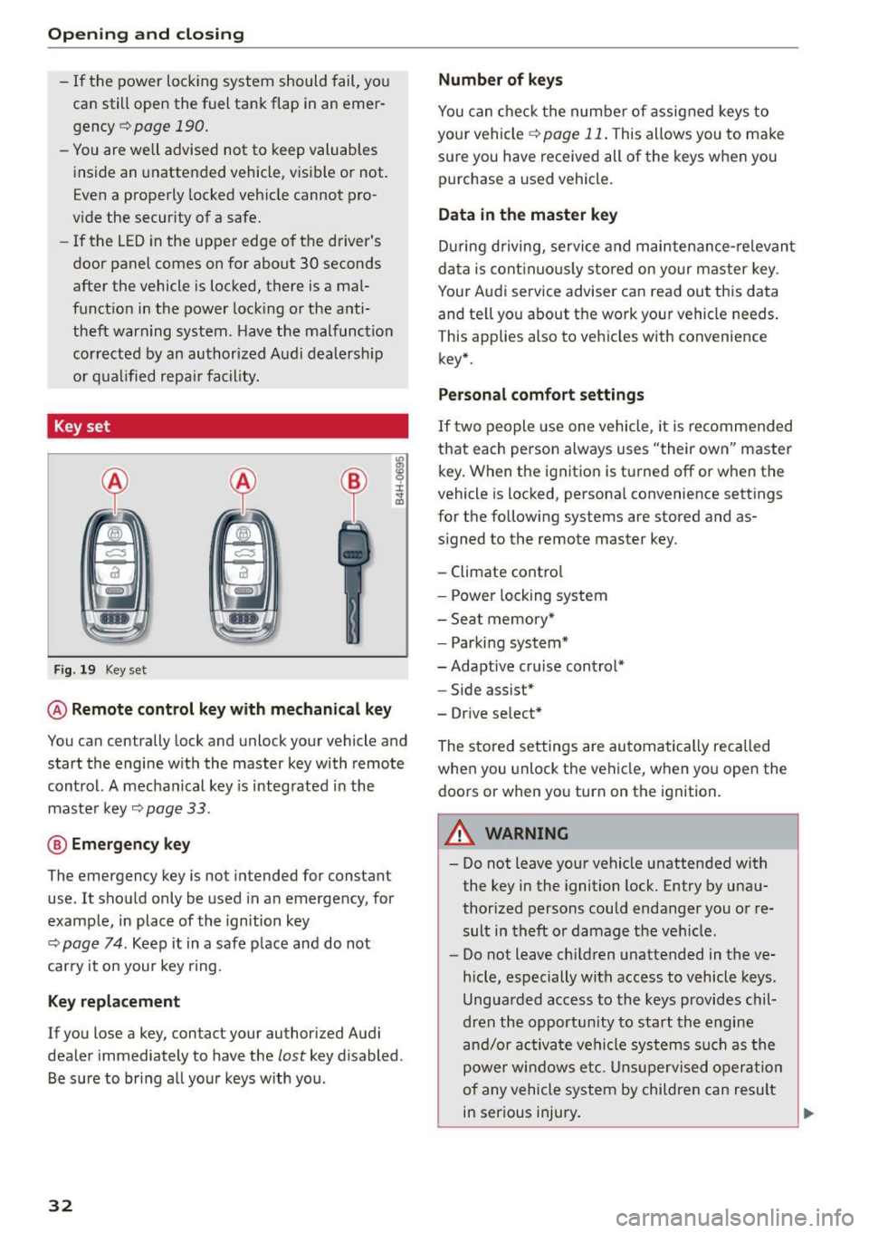
Key set
Fig . 19 Key set
m 0 ±
~
@ Remote control key with mechanical key
You can centrally lock and unlock your vehicle and
start the engine with the master key with remote
control. A mechanical key is integrated in the
master key
~ page 33.
@ Emergency key
The emergency key is not intended for constant
use . It should only be used in an emergency, for
example, in place of the ignition key
~ page 7 4 . Keep it in a safe place and do not
carry it on your key ring.
Key replacement
If you lose a key, contact your authorized Audi
dealer immediately to have the
lost key disabled.
Be sure to bring all your keys with you .
32
Number of keys
You can check the number of assigned keys to
your vehicle
¢ page 11. This allows you to make
sure you have received all of the keys when you purchase a used vehicle.
Data in the master key
During driving, service and maintenance-relevant
data is continuously stored on your master key .
Your Audi service adviser can read out this data
and tell you about the work your vehicle needs.
This applies also to vehicles with convenience
key*.
Personal comfort settings
If two people use one vehicle, it is recommended
that each person always uses "their own" master key. When the ignition is turned off or when the
vehicle is locked, personal convenience settings
for the following systems are stored and as
signed to the remote master key.
- Climate control
- Power locking system
- Seat memory*
- Parking system*
- Adaptive cruise control* - Side assist*
- Drive select*
The stored settings are automatically recalled
when you unlock the vehicle, when you open the
doors or when you turn on the ignition.
A WARNING
-Do not leave your vehicle unattended with
the key in the ignition lock. Entry by unau
thorized persons could endanger you or re
sult in theft or damage the vehicle.
- Do not leave children unattended in the ve
hicle, especially with access to vehicle keys.
Unguarded access to the keys provides chil
dren the opportunity to start the engine
and/or activate vehicle systems such as the
power windows etc. Unsupervised operation
of any vehicle system by children can result
in serious injury.
.
Page 82 of 264
Driving
Speed warning 1: setting a speed limit
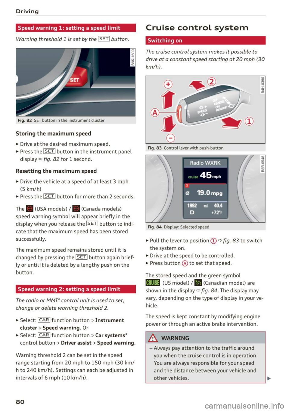
Warning threshold 1 is set by the I SE TI button.
F ig. 82 SET button in the instrument cluster
Storing the m aximum spe ed
• Drive at the desired maximum speed.
• Press the
!SET I button in the instrument p anel
display
c;, fig. 82 for 1 second .
Resetting the ma ximum speed
• Drive the vehicle at a speed of at least 3 mph
(5 km/h)
• Press the
i~S-ET~ I button for mo re than 2 seconds .
The . (USA models) /. (Canada models)
speed warn ing symbol will appear briefly in the
d isplay when you release the
!SETI button to indi
ca te that the max imum speed has been stored
successfully .
The max imum speed remains stored unti l it is
changed by pressing the
! SET I button again br ief
ly or unt il it is deleted by a lengthy p ush on the
button.
Speed warning 2: setting a speed limit
The radio or MMI* control unit is used to set,
change or delete warning threshold 2.
• Se lect: !CARI funct ion button> Instrum ent
clu ster > Sp eed warning .
Or
• Se lect: !CARI funct ion button> Car syste m s*
control button> Dri ver a ss is t> Speed warning .
Warning th reshold 2 can be set in the speed
r a nge starting from 20 mph to 150 mph (30 km/
h to 240 km/h). Settings can each be adjus ted in
interva ls of 6 mph (10 km/h) .
80
Cruise control system
Switching on
The cruise control system makes it possible to
drive at a constant speed starting at
20 mph (30
km/h).
0
f
®l
0
Fig . 83 Contro l lever with push-button
Fi g. 84 D isplay: Selected speed
g M 0 ±
~
Q)
~ ci: Q) m
• Pull the lever to position (D <::> fig. 83 to sw itch
the system on .
• Drive at the speed to be controlled .
• Press button ® to set that speed.
The stored speed and th e green symbol
til;\IJM4 (US mode l)/ El (Canadian model) are
shown in the display
c;, fig. 84. The display may
vary, depending on the type of display in your ve
hicle.
The speed is kept constant by modifying engine
power or through an act ive brake intervention.
A WARNING
-Always pay atte ntion to the traffic around
you when the cruise control is in operation.
You a re always respons ible for your speed
and the distance between your veh icle and
o ther veh icles.
-
Page 83 of 264
M N
i? co
-For reas ons of safety, cruise contro l should
not be used in the city, in stop-and-go traf
fic, on twisting roads and when road condi
t ions are poor (such as ice, fog, gravel,
heavy rain and hydrop laning) -risk of acci
dent .
- Turn off the cruise control temporari ly when
enter ing turn lanes, highway exit lanes or in
construction zones.
- Please note that inadvertent ly "rest ing"
yo ur foot on the accelerator peda l causes
the cruise control not to brake. This is be
c a use the cruise co ntro l is ove rri dden by the
dr iver's acceleration .
-If a brake system malfunc tion such as ove r
he ating occu rs when the c ruise control sys
tem is switche d on, the braking func tion in
the system may be switche d off . The other
c ruise control functions remain active as
long as the indicator light
[lj;(i)~i~ (US mod
els)
! Iii (Canadian mode ls) is on.
(D Tips
- Vehicles with manua l t ransmission: You can
attain the set speed only if the gear t hat is
currently engaged will allow it, or if it does
not tax t he engine and allows it to run
smooth ly. Therefore shift i nto a higher or
l ower gear in a time ly ma nner.
- The brake lights illuminate as soon as the
brakes app ly automatically .
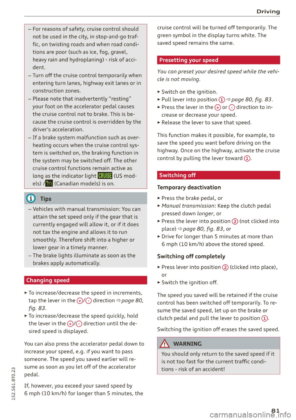
Changing speed
.,. To increase/dec rease the speed in increments,
tap the lever i n the
010 dir ection ¢ page 80,
fig. 83.
.,. To inc rease/de crease the s peed q uickly, hol d
the leve r in the
010 direction until the de
sired speed is displayed.
You c an a lso press the acceler ator peda l down to
increase your spee d, e .g . if you want to pass
someone . The speed you saved ea rlier will re
sume as soo n as yo u let off of the accelerator
pedal.
~ If , however, yo u exceed your saved speed by 1.1'1
~ 6 mph (1 0 km/h) for longe r than 5 mi nutes, the
......
Dri ving
cruise control will be turned off tempora rily. The
green symbo l in the d isp lay turns wh ite . The
saved speed rema ins the same .
Presetting your speed
You can preset your desired speed while the vehi
cle is not moving.
.,. Switch on the ign ition.
.,. Pull leve r into position
(D ¢ page 80, fig . 83 .
.,. Press the leve r in t he 0 o r O direction to in -
crease or decrease your speed .
.,. Release the lever t o save that speed .
This function makes it possib le, for examp le, to
save the speed you want before dr iving on the
highway. Once on the highway, activate the cru ise
control by p ulling the lever toward
(D .
Switching off
Temporary deactivation
.,. Press the brake pedal, or
.,. Manual transmission: Keep the clutch pedal
pressed down
longer, o r
.,. Press the leve r into posit ion @ (not clicked into
p lace) ¢
page 80, fig. 83, or
.,. Dr ive fo r longer t han 5 mi nutes a t more t han
6 mph (1 0 km/h) above the s tore d speed.
Switching off completely
.,. Press lever into position @ (clicked into place),
or
.,. Sw itch t he ignit ion off .
T he speed you saved will be retai ned if the cru ise
co ntrol has been switched off tempora rily . T o re
s u me the saved speed, let up on the brake or
cl utch pedal and pull the lever to position
(D .
Swi tch ing the ignition off erases the saved speed .
A WARNING
--
You should only re turn to the saved speed if it
i s not too f ast for the curren t traff ic condi
ti ons -ris k of an accident!
81
Page 88 of 264
Automatic transmission
¢ page 191. Otherwise, any increase in en
gine speed may set the veh icle in motion,
even with the parking brake applied.
(D Note
- When stopping on an incline, do not try to
hold the vehicle in place by pressing the ac
ce lerator pedal while a driving gear is se
lected. This can cause the transmission to
overheat and can damage it . Activate the
parking brake or press the brake pedal to
prevent the vehicle from rolling.
- Allowing the vehicle to roll when the engine
i s stopped and the selector lever is in
N w ill
damage the transm ission because it is not
lubr icated under those circumstances.
@ Tips
For safety reasons, the park ing brake is re
leased automatically only when the dr iver's
safety belt is engaged in the buckle.
Hill descent control
A pp lies to veh icles: w ith 5 tro nic/t iptronic
The hill descent control system assists the driver
when driving down declines.
Hill descent control is activated when the selec
tor lever is in D/S and you press the brake pedal.
The transmission automatica lly selects a gear
that is suitable for the incline. Hill descent con
trol tries to maintain the speed achieved at the
tim e of braking, within physical and technical
limitations. It may still be necessary to adjust the
speed with the brakes.
Hill descent control switches off once the decline
levels out or you press the acce lerator pedal.
On veh icles w ith the cruise control system*
¢ page 80, hill descent control is also act ivated
when the speed is set.
& WARNING
Hi ll descent control cannot overcome physical
limitations, so it may not be ab le to maintain
a constant speed under all conditions. Always
be ready to apply the brakes.
86
Manual sh ift program
App lies to vehicles: wit h S tron ic/tip tro nic
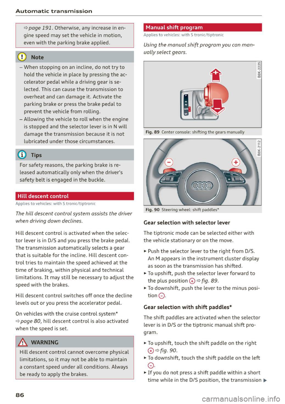
Using the manual shift program you can man
ually select gears.
'
Fig. 89 Center console: shifting the gears manually
Fig. 90 Steering wheel: sh ift padd les•
Gear selection with selector lever
The tiptronic mode can be selected either w ith
the vehicle stationary or on the move.
11> Push the se lector lever to the right from D/S.
An M appears in the instrument cluster display
as soon as the transmission has shifted .
"T o upshift, push the se lector lever forwa rd to
the plus position
G) ¢ fig. 89.
" To downshift, push the lever to the minus posi-
tion
0 .
Gear selection with shift paddles*
The shift paddles are activated when the selector
l ever is in D/S or the tiptronic manual sh ift pro
gram .
" To upshift, touch the shift padd le on the r ight
G) ¢fig. 90.
"To downshift, touch the shift paddle on the left
0 .
11o Ifyou do not press a shift p addle within a short
time while in the 0/5 position, the transmission .,.
Page 91 of 264
M N
0 loo
rl I.O
"' N
"' rl
Audi adapt ive crui se cont rol and bra king gu ard
Audi adaptive cruise
control and braking
guard
Introduction
App lies to vehicles: with Audi adaptive cruise co ntrol
The adaptive cruise control system assists the
driver by regu lating vehi cle speed and helping to
maintain a set distance to the vehicle ahead,
within the limits of the system.
If the system de
tects a moving vehicle up ahead, adaptive cruise
control can brake and then accelerate your vehi
cle. This helps to make driving more comfortable
on long highway stretches.
The braking guard system can warn you about an impend ing collision and initiate braking maneu
vers
¢ page 95.
Adaptive cruise control and braking guard have
technical limitations that you must know, so
p lease read this section carefu lly, understand
how the system works and use them properly at
all times.
General information
General information
A pp lies to vehicles: with Audi adaptive cruise co ntrol
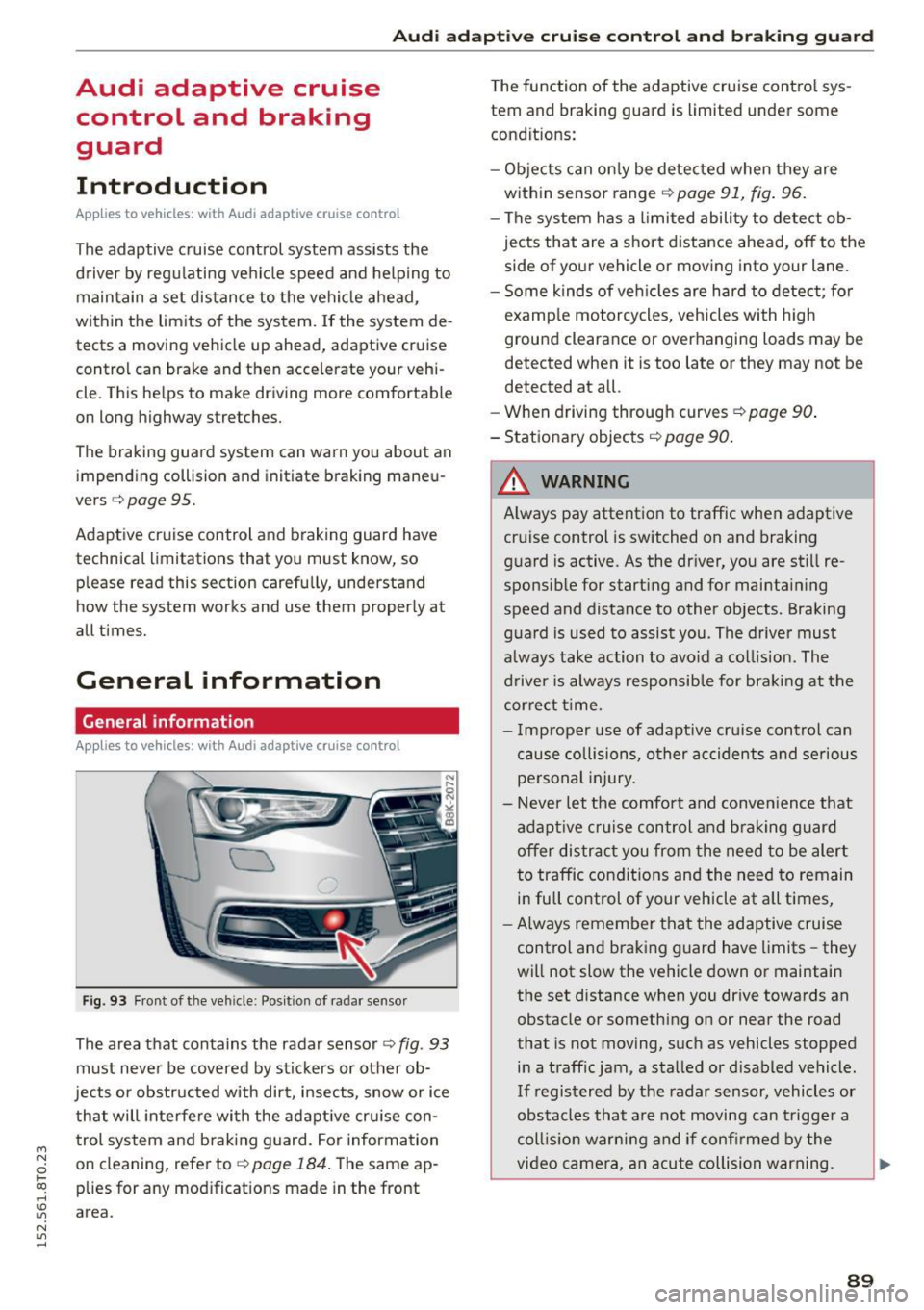
Fig. 93 Fr ont of th e veh icle : Posit ion of radar sensor
The area that contains the radar sensor¢ fig. 93
must never be covered by stickers or other ob
jects or obstructed with dirt, insects, snow or ice
that will inte rfe re with the adapt ive cr uise con
trol system and brak ing guard. For information
on cleaning, refer to ¢
page 184. The same ap
p lies for any mod ificat ions made in the front
area. T
he function of the adaptive cruise cont ro l sys
tem and braking guard is limited under some
condit ions:
- Ob jects can on ly be de tected when they are
with in sensor range¢
page 91, fig. 96.
-The system has a limited ability to de tect ob
jects that are a short distance ahead, off to the
side of your vehicle or moving into your lane .
- Some kinds of veh icles are hard to detect; for
examp le motorcycles, vehicles with high
ground clearance or overhanging loads may be
detected when it is too late or they may not be
detected at all.
- When driving through curves
¢page 90 .
-Stationa ry objects ¢ page 90.
,&_ WARNING
-= -Always pay attention to traffic when adaptive
cruise control is switched on and braking
g uard is active. As the driver, you are still re
sponsib le for start ing and for maintai ning
speed and distance to other objects. Braking
g uard is used to assist you . The drive r must
a lways take action to avo id a col lision . The
d river is always responsible for bra kin g at the
cor re ct t ime.
- I mp roper use of adaptive cruise control can
cau se collisions, o ther accidents and serious
pe rsonal injury.
- Never let the comfort and conve nience that
adapt ive cr uise control and braking guard
offer distrac t you from the need to be alert
to traffic con dit ions and the need to remain
i n full control of your vehicle at all times,
- Always remember that the adaptive cruise
control and braking guard have limits -they
will not slow the vehicle down or maintain
the set distance when you dr ive towards an
obstacle or somethi ng on or near the road
that is not moving, such as vehicles stopped
in a traff ic jam, a sta lled or d isabled vehicle.
If registered by the radar sensor, vehicles or
obstacles that a re not moving can t rigger a
coll is io n warning and if confi rmed by the
video came ra, an acute collision war ning.
~
89