steering AUDI A5 2021 Owners Manual
[x] Cancel search | Manufacturer: AUDI, Model Year: 2021, Model line: A5, Model: AUDI A5 2021Pages: 318, PDF Size: 85.96 MB
Page 4 of 318
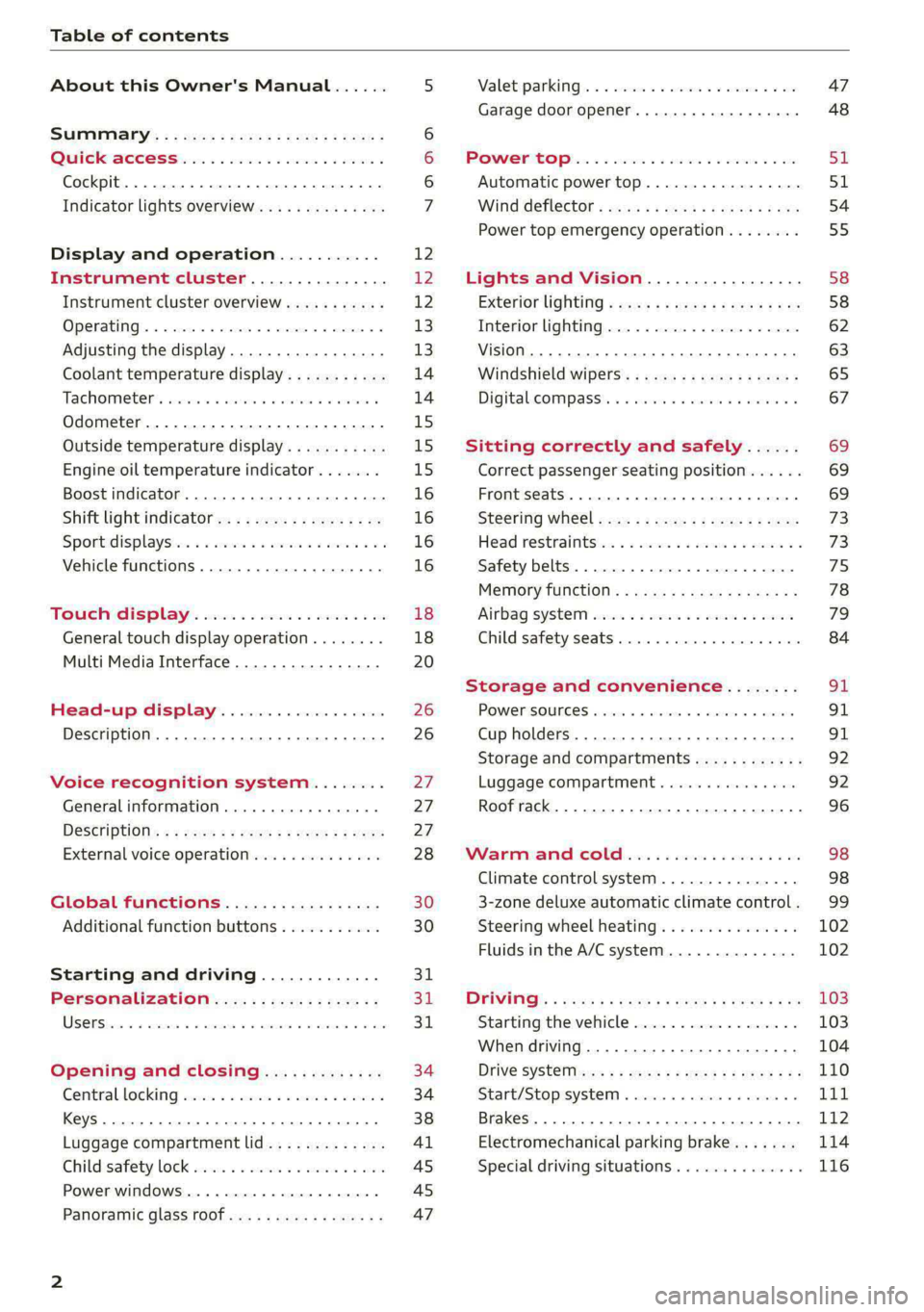
Table of contents
About this Owner's Manual......
SUMIMAry: < = exe : eens: Seen cs sens
QutckeaeCe ssh: «i esis se ois a eaves @
Cockpit. ...... 0... eee eee eee eee
Indicator lights overview...........4..
Display and operation...........
Instrument cluster...............
Instrument cluster overview...........
Operating. ecccuse w+ were oo wens oo ayes 9 ¥
Adjusting the display.................
Coolant temperature display...........
Tachometer’ series i ewe so snes ¥ & ome
Odometer.............. cee eee eee ee
Outside temperature display...........
Engine oil temperature indicator.......
Boost indicator...............0--000.
Shift light indicator..................
Sportidisplaystens « scwne x » eum os vomew «02
Vehicle functions ..............00000.
TOUCH AISPLAY ' sevece: 3 seisas 6 sessen 6 6 ws
General touch display operation........
Multi Media Interface................
Head-up display..................
Description............0.. ee cee eee
Voice recognition system........
General information..............00.
DESGriptiOns « = seen ¢ = seme xs eee st eee
External voice operation..............
Global functions.................
Additional function buttons...........
Starting and driving.............
Personalization..................
Opening and closing.............
Central locking) sani x x swasien © x sponae 2 aaaonor
Keys... eee
Luggage compartment lid.............
Childisafety lock seis 2 « sere ¥ © were 3 ¢ overs
Power windows............000eeeeee
Panorartiic glass roof 0... ieee s ieee es
12 12 12
13
13
14 14
15
15
15
16
16
16
16 18
18
20 26 26 27 27 27
28
30
30
311.
Bi
3,
34
34
38
Al 45 45
47
Valetiparking = s ssse «x cscs ov crue a ¥ oe 47
Garage door opener..........--.00 eee 48
POWOEPRtOP lies. 5 6 sisi. ae sic ao oie & wae 51
Automatic power top................. 51
Wind deflect6r « cccs ss pees sv eeea sv ees 54
Power top emergency operation........ 55
Lights and Vision................. 58
Exteriorlighting « css < «sees < ¢ caew soars 58
Interior lightinGpenis « « sen 0 mew © 2 amore 62
VISION. 2... eee ee eee eee 63
Windshield wipers..................- 65
Digital. compass’. « . ceria ss caw s cei es 67
Sitting correctly and safely...... 69
Correct passenger seating position...... 69
Front seats ....... 0c eee 69
Steering Wheel sows » s wou sg wane x x see 73
Head restraintsti:. «ose a a nase ao oan ae 73
Safety belts. .............0...00000. 75
Memory function..............ee sees 78
‘Airbag SYSteM eviscie co soaae es werae oo eee 79
Child
safety seats... ...... 00... eee eee 84
Storage and convenience........ 91
POWEPISQUIGES vases + arouse « 6 eomaime « + eects 91
Cup holders............. eee eee eee 91
Storage and compartments............ 92
Luggage compartment............... 92
Roof rack... 2.0.2... 2c eee eee eee 96
Warmandicoled ioc. es isco & 6 anes 9 5 ae 98
Climate control system............... 98
3-zone deluxe automatic climate control. 99
Steering wheel heating............... 102
Fluids in the A/C system.............. 102
DYPIVITVE: « eens ¢ & cars ¢ & seme 4 2 HasEE Ee 103
Starting the vehicle.................. 103
When driving.............00eeee eens 104
Drive SYStE Misses ¢ = sawe + « mee se eee sb 110
Start/Stopisystei « sso so aceon 4 @ suena a 111
Brakes... . 2.2.2.0... 2c eee ee eee eee 112
Electromechanical parking brake....... 114
Special driving situations.............. 116
Page 8 of 318
Quick access
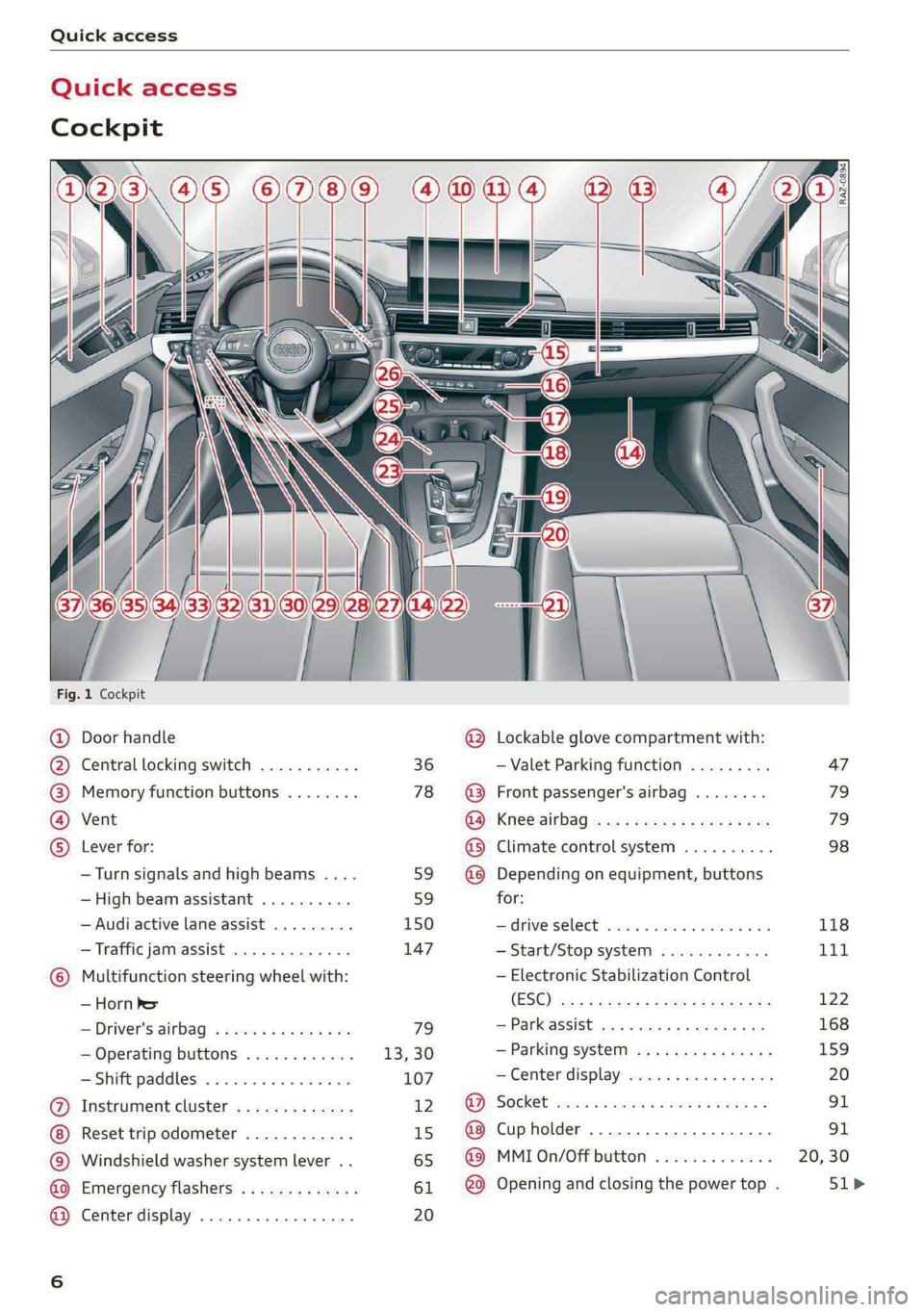
Quick access
Cockpit
Fig. 1 Cockpit
@ @ @ @ ©
©
OO©eCS9
Door handle
Central locking switch
Memory function buttons
Vent
Lever for:
—Turn signals and high beams ....
— High beam assistant ..........
— Audi active lane assist .........
— Traffic jam assist .............
Multifunction steering wheel with:
— Horn he
— Driver's airbag
— Operating buttons
—Shift paddles ................
Instrument cluster .............
Reset trip odometer ............
Windshield washer system lever ..
Emergency flashers .............
Center display .................
36
78
59 59
150 147
79
13,30
107
12 15
65
61 20
®
OOO®
©OO®
Lockable glove compartment with:
— Valet Parking function
Front passenger's airbag
Knee airbag
Climate control system ..........
Depending on equipment, buttons
for:
drive SELCCE cassis «6 sossan © 4 esr © 6s
— Start/Stop system
— Electronic Stabilization Control
(ESC)
— Parkassist os 5 & enies so acs x ¢ ee
— Parking system
—Center display ................
Cup holder ...............0000.
MMI On/Off button
Opening and closing the power top .
[RAZ-0894)
47
79
79
98
118
Tit
122
168
159
Page 9 of 318
8W7012721BB
Quick access
@) Center armrest with storage com-
partment. Depending on vehicle
equipment, it may have:
— Audi music interface .......... 211
—Audi phone box ............... 173
— Starting the engine if there is a
MALFUMERION since oo sxosoue x 2 seems ss 103
@) Electromechanical parking brake
BUGGOT sieves so cman « 2 ewes 2s men 2 114
@) Selector lever (automatic transmis-
SIOM) seo so neon & v Howe & eRe Fa 105
@4 Storage compartment .......... 92
@) [START ENGINE STOP]button .... 103
@6 Audi music interface ............ 211
@) Steering wheel adjustment ...... 73
Lever for:
— Cruise control system ......... 136
— Audi adaptive cruise control .... 139
@9) Button for switching the head-up
display on and off, adjusting the
height ........ 2... cee eee eee 26
60 Instrument illumination ......... 63
@) Connection port for the On Board
Diagnostic System (OBD) ........ 290
@2 Headlight control switch ........ 58
@3) Hood release .............-.0-% 231
@4 All-weather lights button ........ 58
@5) Luggage compartment lid button . 41
G8 Exterior mirror adjustment ...... 63
6 Buttons for:
— Power windows ...........00. 45
— Central power window switch ... 45
—Child safety lock .............. 45
G@) Tips
Some the equipment listed here is only instal-
led in certain models or is available as an op-
tion.
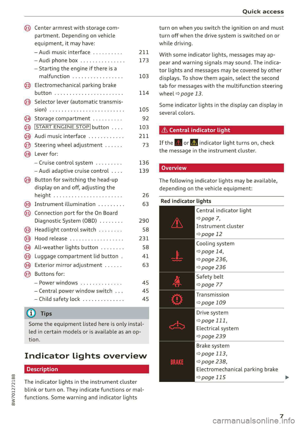
Indicator lights overview
The indicator lights in the instrument cluster
blink or turn on. They indicate functions or mal-
functions. Some warning and indicator lights
turn on when you switch the ignition on and must
turn off when the drive system is switched on or
while driving.
With some indicator lights, messages may ap-
pear and warning signals may sound. The indica-
tor lights and messages may be covered by other
displays. To show them again, select the second
tab for messages with the multifunction steering
wheel > page 13.
Some indicator lights in the display can display in
several colors.
OMe ere ella Uf
If the wA or AN] indicator light turns on, check
the message in the instrument cluster.
(oT T\ i
The following indicator lights may be available,
depending on the vehicle equipment:
Red indicator lights
Central indicator light
=> page 7,
Instrument cluster
=>page 12
Cooling system
=> page 14,
=> page 236,
=> page 236
Safety belt
=> page 77
Transmission
=> page 109
Drive system
> page 111,
Electrical system
=> page 239
Brake system
= page 113,
> page 238,
Electromechanical parking brake
=>page 115 >
Page 10 of 318
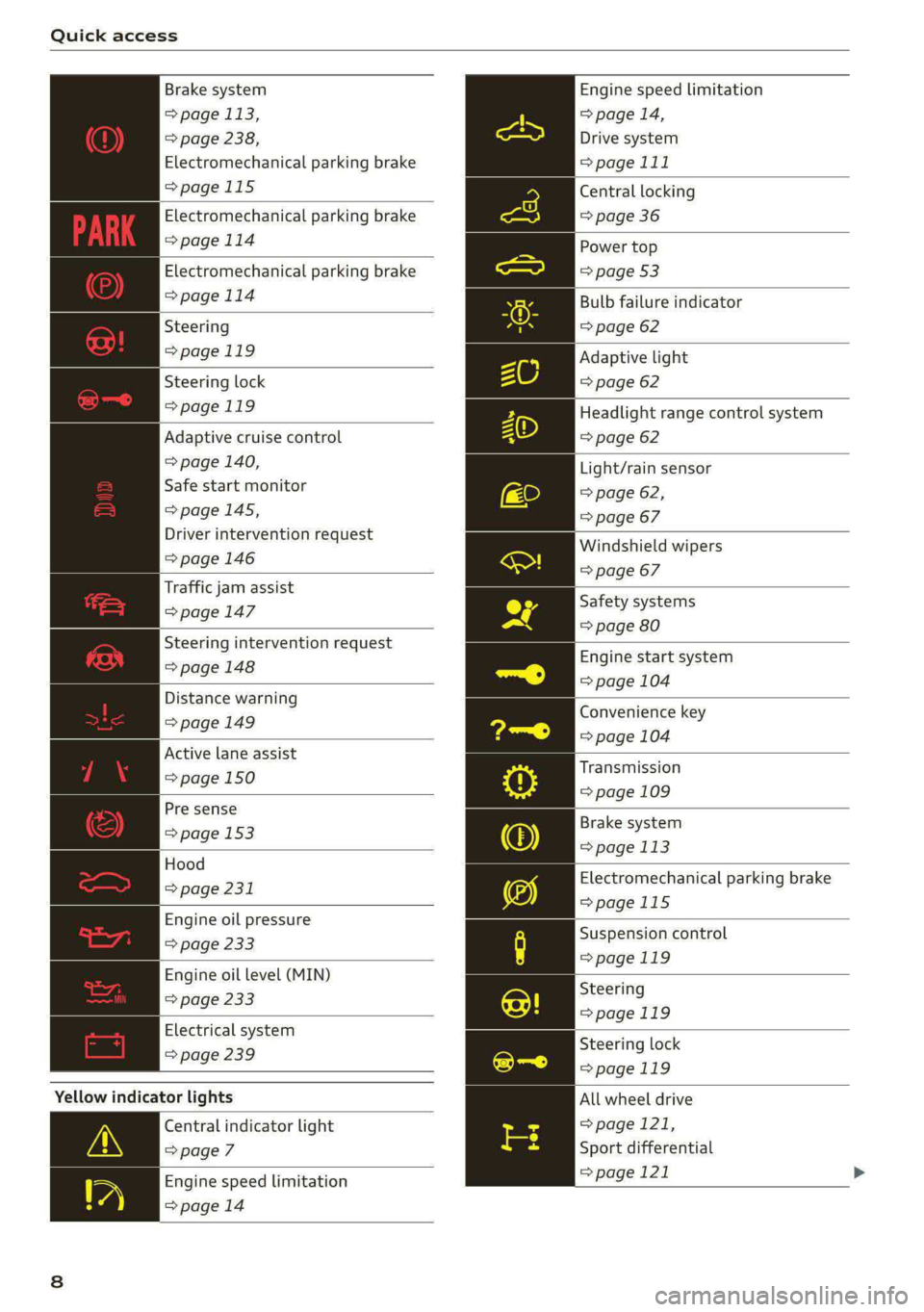
Quick access
Brake system
> page 113,
> page 238,
Electromechanical parking brake
>page 115
Electromechanical parking brake
=>page 114
Electromechanical parking brake
>page 114
Steering
=>page 119
Steering lock
>page 119
Adaptive cruise control
=> page 140,
Safe start monitor
=>page 145,
Driver intervention request
=>page 146
Traffic jam assist
=>page 147
Steering intervention request
=>page 148
Distance warning
=>page 149
Active lane assist
=> page 150
Pre sense
> page 153
Hood
> page 231
Engine oil pressure
=> page 233
Engine oil level (MIN)
=> page 233
Electrical system
> page 239
Yellow indicator lights
Central indicator light
=> page 7
Engine speed limitation
=>page 14
Engine speed limitation
> page 14,
Drive system
>page 111
Central
locking
=> page 36
Power top
=> page 53
Bulb failure indicator
=> page 62
Adaptive light
=> page 62
Headlight range control system
=> page 62
Light/rain sensor
=> page 62,
=> page 67
Windshield wipers
=> page 67
Safety systems
=> page 80
Engine start system
=> page 104
Convenience key
=> page 104
Transmission
=> page 109
Brake system
=> page 113
Electromechanical parking brake
=>page 115
Suspension control
=>page 119
Steering
>page 119
Steering lock
>page 119
All wheel drive
> page 121,
Sport differential
=> page 121
Page 11 of 318

8W7012721BB
Quick access
Electronic Stabilization Control
(ESC)
=> page 122
Electronic Stabilization Control
(ESC)
=> page 122
Electronic Stabilization Control
(ESC)
=> page 122
Anti-lock Braking System (ABS)
=>page 122
Anti-lock Braking System (ABS)
=> page 122
Adaptive cruise control
> page 147,
Traffic jam assist
=> page 148
Steering intervention request
=> page 148,
=>page 151
Distance warning
=> page 149
Active lane assist
=> page 150,
=> page 152
Pre sense
> page 152
Side assist, exit warning
>page 157
Parking systems
=>page 161
Rear cross-traffic assist
>page 165
Park assist
=>page 170
Emergency call function
> page 188
Tank system
=> page 227
Malfunction Indicator Lamp (MIL)
=> page 227,
> page 229
Engine oil level (MIN)
=> page 233
Engine oil level (MAX)
=> page 233
Engine oil sensor
=> page 233
Engine warm-up request
=> page 233
Electrical system
> page 239
Washer fluid level
=> page 242
Tire pressure
=> page 262,
=> page 263,
=> page 265,
=> page 265,
=> page 266
Tire pressure
=> page 263,
=> page 266
Other indicator lights
Low beam headlights
=> page 58
Parking lights
=>page 58
Turn signals
=> page 59,
=> page 61
Turn signals
=>page 59,
=> page 61
Start/Stop system
=> page 111
Cruise control system
=> page 136
Cruise control system
=> page 136
Efficiency assist
=> page 138,
> page 138
Efficiency assist
=> page 138
Page 12 of 318

Quick access
Efficiency assist
=> page 138
Efficiency assist
=> page 138
Efficiency assist
=> page 138
Efficiency assist
=> page 138
Efficiency assist
> page 138
Adaptive cruise control
=> page 140
Adaptive cruise control
=> page 140
Adaptive cruise control
=> page 140
Adaptive cruise control
=> page 140
Adaptive cruise control
=> page 145
Traffic jam assist
=> page 147
Traffic jam assist
=> page 147
Active lane assist
=> page 150
High beam headlights
=> page 59,
=>page 59
High beam assistant
=> page 59,
=> page 60
Laser lights
=> page 60
Child safety lock
=>page 45
Child safety lock
=> page 45
Child safety lock
=>page 45
10
Power top
=> page 53
High beam assistant
=> page 59,
=> page 60,
=> page 62
Convenience key
=> page 104
Transmission
=> page 109
Start/Stop system
> page 112
Electromechanical parking brake
>page 115
Electromechanical parking brake
=>page 115
Hold assist
=>page 115
Steering
=>page 119
Speed warning system
=> page 130
Speed warning system
= page 130
Camera-based traffic sign recog-
nition
> page 131
Cruise control system
=> page 136,
=> page 137,
=> page 137
CRUISE
Cruise control system
=> page 136,
=> page 137,
=> page 137
Efficiency assist
=> page 138,
Predictive control
> page 143,
Adaptive cruise control
=> page 147,
Traffic jam assist
=>page 148
Adaptive cruise control
=> page 143
Page 15 of 318
8W7012721BB
Instrument cluster
vehicle safely. See an authorized Audi dealer
or authorized Audi Service Facility for assis-
tance.
G) Tips
— The following pages primarily show illustra-
tions of the Audi virtual cockpit*. The dis-
play or location of the items that are shown
may vary on the different versions of the in-
strument cluster.
— You can select the units used for tempera-
ture, speed, and other measurements
=> page 221.
— Speeds are displayed in mph (miles per
hour) or km/h (kilometers per hour).
— Certain instrument cluster content can also
be displayed in the head-up display*
=> page 26.
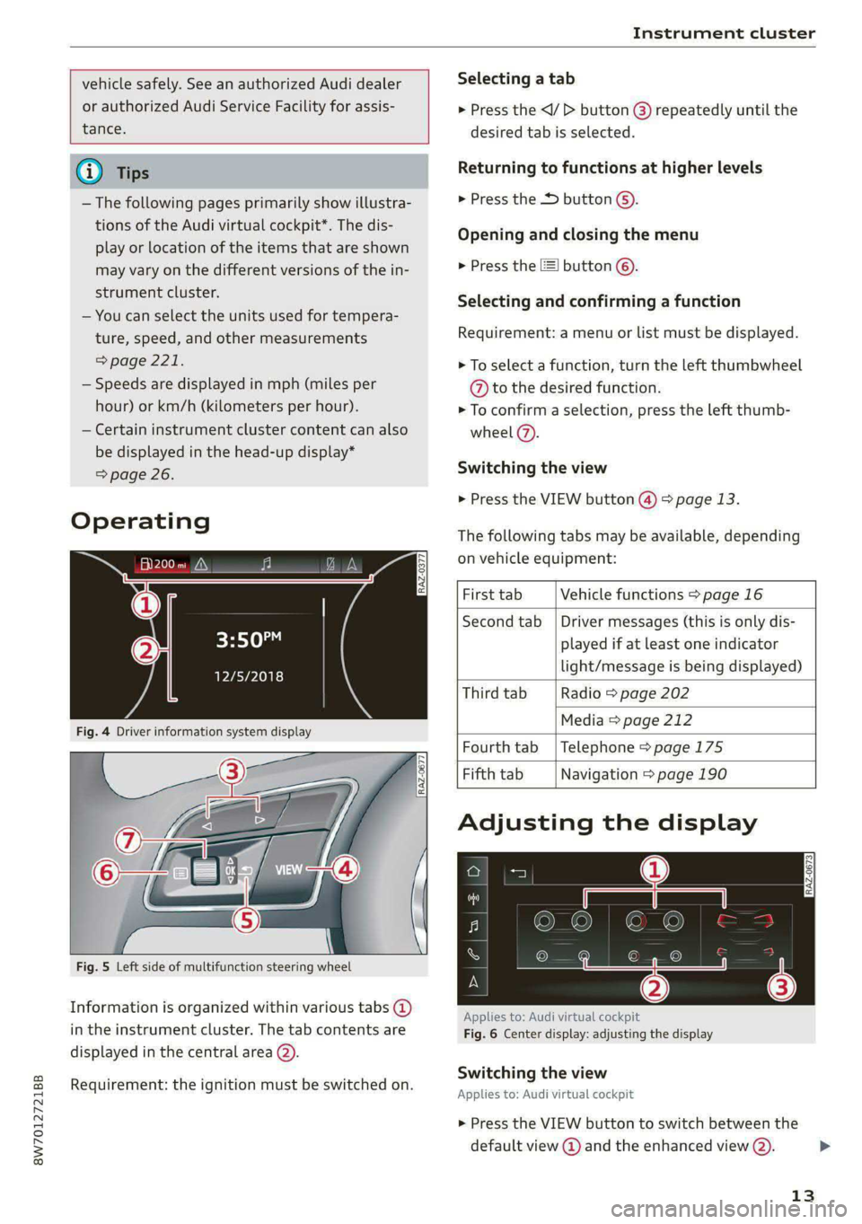
Operating
Fig. 5 Left side of multifunction steering wheel
Information is organized within various tabs @)
in the instrument cluster. The tab contents are
displayed in the central area (2).
Requirement: the ignition must be switched on.
RAZ-0377
Selecting a tab
> Press the
desired tab is selected.
Returning to functions at higher levels
> Press the D button ©).
Opening and closing the menu
» Press the [=] button ©).
Selecting and confirming a function
Requirement: a menu or list must be displayed.
> To select a function, turn the left thumbwheel
@ to the desired function.
> To confirm a selection, press the left thumb-
wheel (7).
Switching the view
> Press the VIEW button @) > page 13.
The following tabs may be available, depending
on vehicle equipment:
First tab Vehicle functions > page 16
Second tab | Driver messages (this is only dis-
played if at least one indicator
light/message is being displayed)
Third tab Radio > page 202
Media > page 212
Fourth tab | Telephone > page 175
Fifth tab Navigation > page 190
Adjusting the display
RAZ-0673
Applies to: Audi virtual cockpit
Fig. 6 Center display: adjusting the display
Switching the view
Applies to: Audi virtual cockpit
> Press the VIEW button to switch between the
default view @ and the enhanced view (2).
13
Page 16 of 318

Instrument cluster
Adjusting the layout
Applies to: Audi virtual cockpit
Depending on the vehicle equipment, various lay-
outs may be available.
> Applies to: MMI: Select on the home screen:
SETTINGS > Display & brightness > Audi virtu-
al cockpit.
> To adjust the desired layout, press @).
Setting the automatic layout change
Applies to: RS model with Audi virtual cockpit
Requirement: depending on vehicle equipment,
the RS Performance or RS Runway layout must
be set.
> Applies to: MMI: Select on the home screen:
SETTINGS > Display & brightness > Audi virtu-
al cockpit > Configure > Automatic activation
of RS layout.
Depending on vehicle equipment, the RS Per-
formance or RS Runway layout will be automati-
cally set when switching into the RS modes
=>page 118.
Adjusting the additional display
Applies to: Audi virtual cockpit
Depending on the vehicle equipment, the addi-
tional displays that can be selected may vary.
> Applies to: MMI: Select on the home screen:
SETTINGS > Display & brightness > Audi virtu-
al cockpit > Configure.
> Select the desired additional display.
Reducing the display
Depending on the vehicle equipment, you can
hide the central area in the instrument cluster.
> Select on the instrument cluster: vehicle func-
tions tab > [I] button > Reduced display, or
> Press the VIEW button on the multifunction
steering wheel.
Coolant temperature
display
Applies to: vehicles with a coolant temperature indicator
The coolant temperature display @) > page 12
only functions when the ignition is switched on.
14
To reduce the risk of engine damage, please ob-
serve the following notes about the temperature
ranges.
Cold range
If only the LEDs at the bottom of the gauge turn
on, the engine has not reached operating tem-
perature yet. Avoid high engine speeds, full accel-
eration, and heavy engine loads.
Normal range
The engine has reached its operating tempera-
ture once the LEDs up to the center of the gauge
turn on. If the BB indicator light in the instru-
ment cluster display turns on, the coolant tem-
perature is too high > page 236.
C) Note
— Auxiliary headlights and other accessories in
front of the air intake impair the cooling ef-
fect of the coolant. This increases the risk of
the engine overheating during high outside
temperatures and heavy engine load.
— The front spoiler also helps to distribute
cooling air correctly while driving. If the
spoiler is damaged, the cooling effect will
be impaired and the risk of the engine over-
heating will increase. See an authorized
Audi dealer or authorized Audi Service Fa-
cility for assistance.
Tachometer
The tachometer (@) 9 page 12 displays the engine
speed in revolutions per minute (RPM). The be-
ginning of the red zone in the tachometer indi-
cates the maximum permissible engine speed for
all gears once the engine has been broken in. Be-
fore reaching the red zone, you should shift into
the next higher gear, select the "D" or "S" selec-
tor lever position, or remove your foot from the
accelerator pedal.
Engine speed limitation
If the tA indicator light turns on, the engine will
be automatically limited to the RPM displayed in >
Page 18 of 318
Instrument cluster
cause for concern as long as the B or 3 indica-
tor lights do not turn on.
Boost indicator
Applies to: vehicles with boost indicator
Depending on vehicle equipment, the current en-
gine load (meaning the current boost pressure)
may be indicated by a bar in the instrument clus-
ter.
> Applies to: vehicles with Audi virtual cockpit:
Open the vehicle functions tab and switch to
the enhanced view > page 13.
> Applies to: vehicles with analog instrument
cluster: Open the lap timer > page 133.
Shift light indicator
Applies to: RS models
The shift light indicator informs the driver when
the RPM limit is reached.
» Applies to: vehicles with Audi virtual cockpit:
Set the RS Performance or RS Runway layout if
necessary > page 13.
» Applies to: vehicles with analog instrument
cluster: Open the lap timer > page 133.
The shift light indicator is displayed with green,
yellow and red ranges in the upper areas of the
tachometer. The shift light indicator will blink red
when approaching the engine speed limit. Shift
to the next highest gear at the right time.
Sport displays
Applies to: RS models
Various sport displays, such as a G meter or tire
pressure indicator, may be available depending
on vehicle equipment.
Opening sport displays in the instrument
cluster
Applies to: vehicles with Audi virtual cockpit
> Select in the instrument cluster: Vehicle func-
tions tab > EE] button > Sport displays.
> Turn the left thumbwheel on the multifunction
steering wheel until the desired sport display
appears in the instrument cluster.
16
Opening sport displays in the MMI
> Applies to MMI: Select on the home screen: VE-
HICLE > RS monitor.
> Browse to the desired display if necessary.
G meter
Applies to: vehicles with Audi virtual cockpit
The G meter displays the longitudinal and lateral
acceleration. The current values are displayed in
the instrument cluster while driving. The maxi-
mum values that are reached are stored and dis-
played when the vehicle is stationary. Only the
maximum values that are reached are displayed
in the MMI.
> To reset the stored values, press and hold the
left thumbwheel on the multifunction steering
wheel for one second.
Tire pressure
The tire pressure monitoring system displays the
current tire pressures and temperatures. Also see
=> page 263, Tire pressure monitoring system.
Engine data
Applies to: vehicles with Audi virtual cockpit
The engine data in the instrument cluster shows
which percentage of the maximum output or
maximum torque is currently being used.
Temperature
The temperature display in the MMI shows the
temperature of various fluids and vehicle compo-
nents, such as the engine oil or sport differential.
Vehicle functions
(OTe TWN]
The trip computer is displayed in the first tab of
the driver information system. Additional vehicle
functions can be accessed depending on the vehi-
cle equipment.
> Press the =] button on the multifunction steer-
ing wheel.
— On-board computer > page 17
— Sport displays > page 16
— Lap times > page 133
Page 19 of 318

8W7012721BB
Instrument cluster
— Lap statistics > page 133
— Acceleration measurement > page 134
— Reduced display > page 14
On-board computer
Resetting values to zero
Requirement: the Consumption, Short-term
memory, or Long-term memory display must be
selected.
> To reset the values in the respective memory to
zero, press and hold the left thumbwheel on
the multifunction steering wheel for one sec-
ond.
Depending on the vehicle equipment, you can call
up the following displays in the on-board com-
puter one at a time by turning the left thumb-
wheel on the multifunction steering wheel:
—Time and date > page 221
— Level
— Digital speedometer
— Average consumption > page 17
— Range
— Short-term memory overview
— Long-term memory overview
— Energy consumers > page 17
— Driver assistance
— Traffic sign recognition and traffic light infor-
mation
Short-term memory and long-term memory
The short-term memory collects driving informa-
tion from the time the ignition is switched on un-
til it is switched off. If you continue driving within
two hours after switching the ignition off, the
new values will be included when calculating the
current trip information.
Unlike the short-term memory, the long-term
memory is not erased automatically. You can se-
lect the time period for evaluating trip informa-
tion yourself.
Average consumption
The current consumption can be shown using a
bar graph. The average consumption stored in
the short-term memory is also displayed. If the
bar is green, your vehicle is saving fuel (for exam-
ple, using recuperation).
Energy consumers
The Energy consumers view lists other equip-
ment that is currently affecting fuel consump-
tion. The display shows up to three equipment
items. The equipment using the most power is
listed first. If more than three items using power
are switched on, the equipment that is currently
using the most power is displayed. A gauge also
shows the current total consumption of all other
equipment.
G) Tips
The date, time of day, and time and date for-
mat can be set > page 221.
17