Engine AUDI A5 CABRIOLET 2011 Owners Manual
[x] Cancel search | Manufacturer: AUDI, Model Year: 2011, Model line: A5 CABRIOLET, Model: AUDI A5 CABRIOLET 2011Pages: 364, PDF Size: 86.48 MB
Page 331 of 364
__________________________________________ __!F~U!_.:!S~e:.:s~ a~n~d:!_..!:b~u:!!l~b~s~ _J
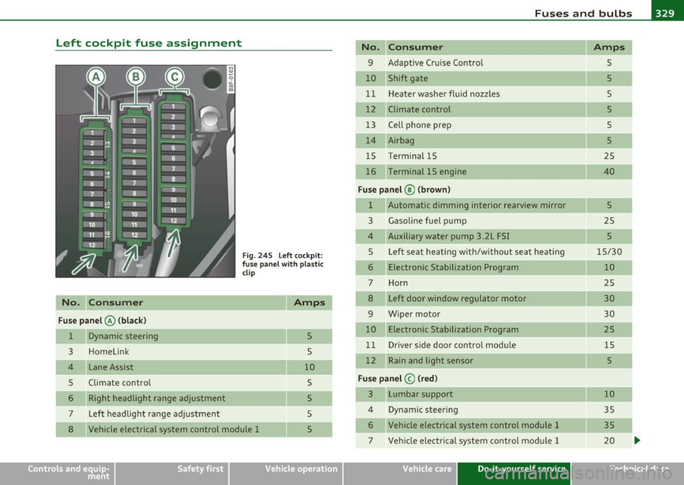
Left cockpit fuse assignment
No. C onsumer
Fus e pa nel @ (black )
1 Dynamic steering
3 Homelink
4 Lane Assist
5 Climate control Right headlight range adjustment
7 Left headlight range adjustment
Fig. 2 4 5 Left cock pit :
fuse pan el with plastic
cl ip
5
5
10 5
5
5
8 Vehicle electrical system control module 1 5
Vehicle OP-eration
No. Consumer Amps
9 Adaptive Cruise Control
5
10 Shift gate 5
1 1 Heater washer fluid nozzles
5
12 Climate control 5
13 Ce lt phone prep
s
14 Airbag
5
15 Term
inal 15
25
16 Terminal 15 engine 40
Fus e pa nel ® (brow n)
1 Automatic dimming interior rearview mirror 5
3 Gasoline fuel p ump 25
4 Auxiliary water pump 3 .2L FSI 5
5 Left seat heating with/wi tho ut seat heat ing 15/30
6 Electronic Stabilization Program
10
7 Horn 25
8 Left door window regulator motor 30
9 Wiper motor 30
10 Electronic Stabilization Program
25
11 Driver side door control modu le 15
12 Rain and light sensor 5
Fuse panel © (red)
3 Lumbar support 10
4 Dynamic steer
ing
35
6 Vehicle electrical system control module 1 35
7 Veh icle elect rical system control module 1 20
Vehicle care Do-it-yourself service iTechnical data
Page 334 of 364

-Fuses and bulbs Pf":I..._ ______________ _
No. Consumer
11 Rear seat hea ting
1 2 T ermin al 15 con trol modules
Fuse panel © (black)
3 D SP am plifi er, radio
4 MMI
5 Radio/navigation/cell phone prep
6 Rearvie w camer a
7 cell phone p rep
Bulbs
Replacing bulbs
Amps
5
5
30
7,5
5
5
5
F or your safety, we recomm end that you have your autho
riz ed Audi dealer replace any bulbs for you .
It is becoming increasing ly mo re and more d ifficult to replace vehicle
light bulbs since in many cases, other parts of the car must f irst be
removed before yo u are ab le to get to the bu lb. This app lies especially
to the light bulbs in the front of your car which you can only reac h
t hrough the eng ine comp artment.
Sheet metal and bu lb holders can have sharp edges that can cause
serious c uts, parts must be correctly taken apart and then properly
put back together to he lp prevent breakage of parts and long term
damage from water t hat can enter housings that have not been prop
erly resea led.
For your safety, we recommend that you have your authorized Audi
dealer replace a ny bu lbs for yo u, since yo ur dealer has the proper
too ls, t he cor rect bu lbs and the expertise.
Gas discharge lamps (Xenon lights)*:
•
Due to the high electrical voltage, have the bulbs replaced by a qua l
ified techn ici an . Hea dligh ts w ith Xenon light are i dent ified by t he
hig h voltage sticker.
& WARNING
Changing Xenon lamps without the necessa ry equipment can
c aus e seriou s personal injury.
• Bulbs are pressurized and can e xplode when being changed.
Potential risk of injury!
• On veh icle s equipped with gas discharge bulbs (Xenon light)*
life-threatening injuries can result from improper handling of the
high- voltage portions of such lamps!
• Only your authorized Audi dealer or a qualified workshop
should change the bulbs in gas discharge lamps. There are parts
with sharp edges on th e openings and on the bulb holder s that can
cause serious cuts. If you are uncertain about what to do , have the
work performed by an authorized Audi dealer or other qualified
workshop . Serious personal injury m ay result from improperly
performed work.
[ i ] Tips
• If yo u still p refer to rep lace the l igh t bul bs yourself, be aw are t hat
the engine compartment is a hazardous area to work in~
page 272,
"En gine compartment" ~& .
• It is best to ask your authorized Audi dealer whenever you want to
c h ange a bulb. •
Page 335 of 364
Emergency situations --------------=----Efffll
Emergency situations
General
This chapter is intended for trained emergency crew s and working
personnel who ha ve the necessar y tools and equipment to perform
the se operations . •
Starting by pushing or towing
(D Note
Vehicles with an automatic transmis sion cannot be started by
pushing or towing .•
Starting with jumper cables
If necess ary, the engine can be started by connecting it to
the battery of an other vehicle .
If the engine shou ld fai l to start because of a discharged or weak
battery, t he battery can be co nnecte d to the battery of
another
vehicle, using a pair of jumper cable s to start the engine .
Jumper cables
Use only jumper cables of suffic ient ly large cross section to carry the
sta rter cur ren t safely . Refe r to the manufacture r's specifications.
Use on ly j umper cab les with
insulated te rm ina l clamps w hich are
distinct ly marked :
plus(+) cable in most cases colo red red
minus (-) cable i n most cases colored black.
Safety first
& WARNING
Batterie s contain electricity, acid, and gas . Any of these can cause
very serious or fatal injury . Follow the inst ructions below for safe
handling of your vehicle 's battery .
• Always shield your eyes and avoid leaning over the battery
whenever possible.
• A discharged battery can freeze at temperatures just below
32 °F (0 °C). Before connecting a jumper cable, you must thaw the
frozen battery completely , otherwise it could explode.
• Do not allow battery acid to contact eyes or skin . Flush any
contacted area with water immediately .
• Improper use of a booster battery to start a vehicle may cause
an e xplosion.
• Vehicle batteries generate e xplos ive gases. Keep spa rks, flame
and lighted cigarettes away from batteries.
• Do not try to jump start any vehicle with a low acid level in the
battery.
• The voltage of the booster battery must also h ave a 12 -Volt
rating. The capacity (Ah) of the booster battery should not be
lower than that of the discharged battery. Use of batter ies of
different voltage or sub stantially different "Ah " rating may cau se
an explosion and personal injury.
• Never charge a frozen battery . Ga s trapped in the ice may cause
an e xplosion.
• Never charge or use a battery that has been frozen. The battery
case may have be weakened.
• Use of batteries of different voltage or substantially different
capacity (Ah ) rating may cause an explosion and injury . The
capacity (Ah ) of the booster battery should not be lower than that
of the discharged battery. _..
Vehicle care Do-it-yourself service Technical data
Page 336 of 364
,..,___E_ m_ e_r -=g :.. e_ n_c -=y '-- s_i_t _u _a _ t_ i_ o _ n_ s ____________________________________________ _
& WARN ING (con tin ue d)
• Before you che ck anything in the engine compartment, always
read and heed all WARNINGS~
page 272, "Engine compart
ment ".
0 Note
• App lying a higher vo ltage booster battery will cause expens ive
damage t o sens it ive e lec tron ic compone nts, such as contro l units,
re lays, rad io, etc.
• The re must be no elect rical contact between the veh icles as othe r
w ise current could already start to flow as soon as the pos it ive( +)
t erminals a re connected.
[ i ] Tips
Th e d ischarged ba ttery mus t be p roper ly connec ted to t he veh icle's
electrical system. When jump starting or charging the battery , never
conne ct the negative grou nd ca ble to the ba ttery negative post
because the battery manager system must be ab le to detect the
ba ttery's state of charge. A lways connec t the negat ive g round cable
to the negative ground post of t he battery manager cont rol un it .•
Use of jumper cables
fvf ake sure t o con nect the j umpe r ca ble clam ps i n ex a ctly
the order describ ed belo w!
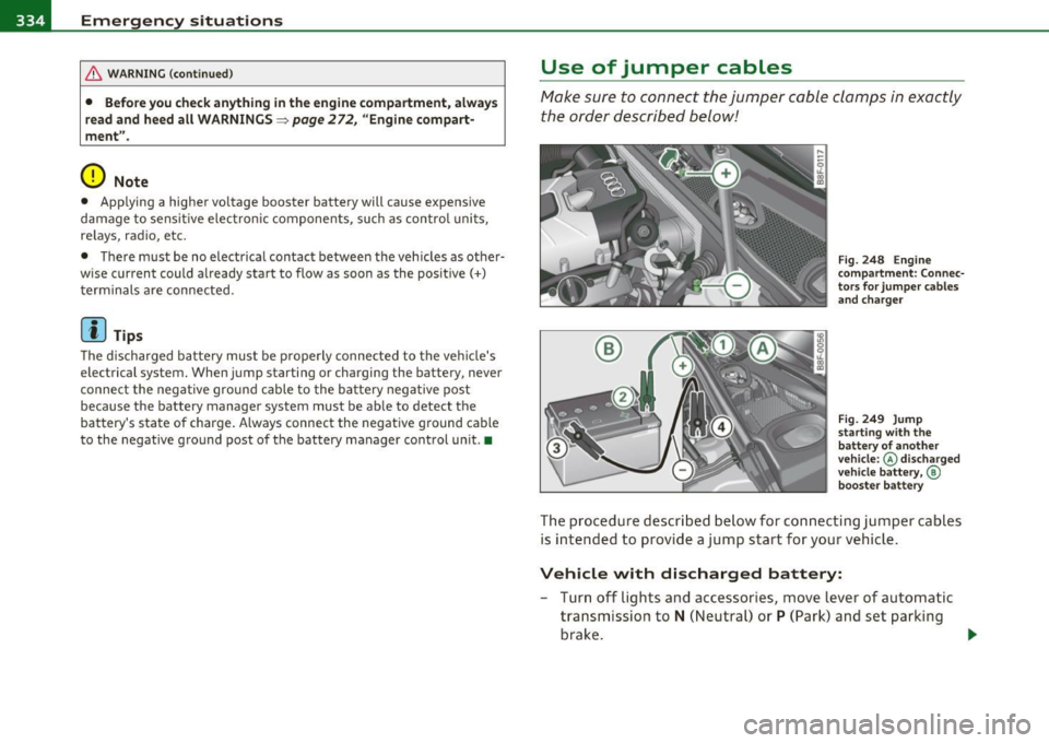
Fig. 248 Engine
comp artment : Co nnec
t o rs f or jump er cabl es
a nd c harger
Fig . 249 Jump
sta rtin g with the
b at tery of another
ve hicle :@ disc harge d
v ehicle battery ,©
bo oste r battery
The procedure descri bed below for con nec ting ju mper cables
is i nten ded to prov ide a jump start for your veh icle .
Vehicle with discharged battery:
-Turn off lights and accesso ries, move l ever of au to m atic
tra nsmi ssio n to
N (Ne utr al) or P (Park) an d se t parking
bra ke .
~
Page 337 of 364

Emergency situations Ill
-------------=----
Connect POSITIVE (+) to POSITIVE (+) (red)
- Remove the cover above the jump start connectio n.
- Open the red cover o n the positive pole~
page 334,
fig. 248.
1 . Connect one e nd of the pos it ive cable ( red) on the
jump
start bolt~
page 334, fig. 249 (D (Bolts under red cover
= "positive") of the veh ic le to be started @.
2 . Connect the other end to the positive te rminal @ of the
booster ba ttery @.
Connect NEGATIVE(-) to NEGATIVE(-)
(black)
3. Con nect o ne end to the negative ter minal ® of the
boost er batte ry @ .
4. Connect the other end o f the nega tive cab le (black) to the
jump start bolt© (Bolts with hex head = "ne gative") of
the vehicle to be starte d @ .
Starting the engine
- Start the e ngine of t he ve hic le w ith the boos ter ba ttery.
Run the engine at a moderate speed.
- Start eng ine w it h discharged ve hicle bat tery in t he usu al
manner .
- If the engine fai ls to sta rt: do not k eep the s tarter
c ra nki ng for longer tha n 1 0 seco nds. Wait for a bou t
30 se conds and then t ry again.
- With engine ru nni ng, remove jumper cables from bot h
ve hicle s in th e exac t
re verse ord er.
- Close t he red cover on the pos it ive po le.
Safety first
T he battery is vented to the outside to prevent gases from enter ing
t he ve hicl e inter ior. Make su re tha t the ju mper clamps are we ll
connected with the ir
metal parts in full contact with the battery
terminals .
& WARNING
To avoid serious personal injury and damage to the vehicle, heed
all warnings and instructions of the jumper cable manufacturer . If
in doubt, call for road service .
• Jumper cables must be long enough so that the vehicles do not
touch.
• When connecting jumper cables , make sure that they cannot
get caught in any moving part s in the engine compartment .
• Do not bend over the batteries · danger of chemical burns!
• The battery cell locking screws mu st be tightened securely .
• Before you che ck anything in the engine compartment, always
read and heed all WARNINGS=>
page 272, ''Eng ine compart
ment ".
0 Note
Imprope r hoo k-up o f jumpe r cab les can ruin the gene rator.
• Always connect POSITIVE( +) to POSITIVE(+), and NEGATIVE( -)
t o NEG ATI VE( -) ground pos t of the ba tte ry m anag er cont rol unit.
• Check that all sc rew p lugs on the battery cells are screwed in
fi rm ly . If no t, tig hten plugs prio r to con nectin g clamp on neg ative
battery terminal.
• P lease note that the proced ure for connecting a jumper cable as
described above app lies specifically to the case of your vehicle being
jum p st arted. When you a re giving a jump sta rt to anot her vehicle, do
not connect the negative( -) cab le to the negative (-) terminal on the
discharge d batte ry © =>
page 334, fig. 249 . Instea d, sec urely
connect the negative( -) cable to either a solid meta l component t hat
is f irm ly bolted to t he eng ine b lock or to the eng ine b lock itself. If the .,_
Vehicle care Do-it-yourself service Technical data
Page 338 of 364
lffll.,___E_ m_ e_r-=g :.. e_ n_c -=y '-- s_i_t _u _a _ t_ i_ o _ n_ s ____________________________________________ _
battery that is being charged does not vent to the outside, escaping
battery gas could ignite and explode! •
Emergency towing with
commercial tow truck
General hints
Your Audi requires special handling for towing.
The following information is to be used by commercial tow truck
operators who know how to operate their equipment safely.
• Never tow your Audi, towing will cause damage to the engine
and transmission.
• Never wrap the safety chains or winch cables around the brake
lines.
• To prevent unnecessary damage, your Audi must be transported
with a flat bed truck.
• To load the vehicle on to the flat bed, use the towing loop found
in the vehicle tools and attach to the front or rear anchorage
~ page 336 and ~ page 33 7.
& WARNING
A vehicle being towed is not safe for passengers. Never allow
anyone to ride in a vehicle being towed, for any reason. •
Front towing loop
Do not install the front towing loop until it is needed.
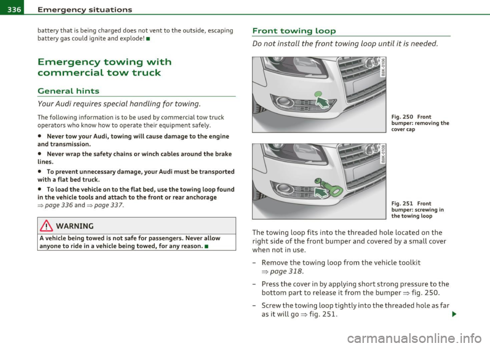
Fig. 250 Front
bumper: removing the
cover cap
Fig. 251 Front
bumper: screwing in
the towing loop
The towing loop fits into the threaded hole located on the
right side of the front bumper and covered by a small cover
when not in use.
- Remove the towing loop from the vehicle toolkit
~page 318.
- Press the cover in by applying short strong pressure to the
bottom part to release it from the bumper~ fig. 250.
- Screw the towing loop tightly into the threaded hole as far
asitwillgo~fig. 251. ..,
Page 341 of 364

_____________________________________________ E_ m_ e_r-= g ::.. e_ n_c-= y'- s_ i_t _u _a_ t_ i_ o _ n_ s __ _
& WARNING
• To reduce the risk of serious injury and vehicle damage.
-Always lift the vehicle only at the special workshop hoist and
floor jack lift points illustrated=>
page 338, fig. 254 and
=> page 338, fig. 255.
- Failure to lift the vehicle at these points could cause the
vehicle to tilt or fall from a lift if there is a change in vehicle
weight distribution and balance. This might happen, for
example, when heavy components such as the engine block or
transmission are removed .
• When removing heavy components like these, anchor vehicle
to hoist or add corresponding weights to maintain the center of
gravity. Otherwise , the vehicle might tilt or slip off the hoist ,
causing serious personal injury.
0 Note
• B e aw are of the following poi nts b efo re li fting the ve hicl e:
- The vehicle should never be lifted or jacked up from under
neath the engine oil pan, the transmission housing , the front or
rear axle or the body side members . This could lead to serious
damage.
- To avoid damage to the underbody or chassis frame, a rubber
pad must be inserted between the floor jack and the lift points.
- Before driving over a workshop hoist, check that the vehicle
weight does not exceed the permissible lifting capacity of the hoist.
- Before driving over a workshop hoist, ensure that there is
sufficient clearance between the hoist and low parts of the
vehicle. •
Safety first Vehicle care Do-it-yourself service Technical data
Page 342 of 364
___ G_ e_n_ e_r _a _ l_ in_ f_o _r_ m_ a_ t_io _ n _______________________________________________ _
General information
Explanation of technical data
Some of the technical data listed in this manual requires
further explanation.
The technical data for your vehicle is listed in the charts starting on
~ page 342 . This sect ion prov ides genera l information, notes and
restrictions which app ly to this data .•
Veh icle identification
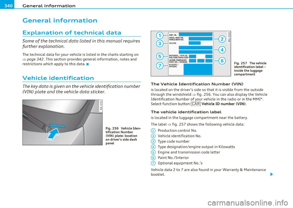
The key data is given on the vehicle identification number
(VIN) plate and the vehicle data sticker.
F ig. 256 V ehicle I den
t ifi ca tion Nu mbe r
(V IN ) pl ate: locat io n
o n d river's s id e d ash
p an el Fi
g. 257 The vehi cle
i d enti ficati on l abel -
in side the l ugga ge
co mpa rtme nt
The Vehicle Id ent ifi cat ion Number (VlN )
is located on the driver's s ide so that it is visible from the outside
throug h the windsh ield ~ fig . 256 . You can also d isp lay the Vehicle
Identification Number of your vehicle in the radio or in the MMI*.
Select function button [ CAR
l Veh icle ID numb er (VIN) .
The vehicle identifica tion label
is located in the luggage compartment near the battery .
The label~ fig . 257 shows the following vehicle data:
© Production control No.
@ Vehicle identification No.
® Type code n umber
@ Type designat io n/eng ine output in Kilow atts
© Engine and transmission code letter
© Paint No./Interior
(j) Optional equipment No.'s
Vehicle data 2 to 7 are also found in your Warranty
& Maintenance
booklet . .,,
Page 344 of 364
___ D_ a_t _a _____________________________________________________ _
Data
Applie s to ve hicle s: with 2 .0 lit er 4- cyl. engin e
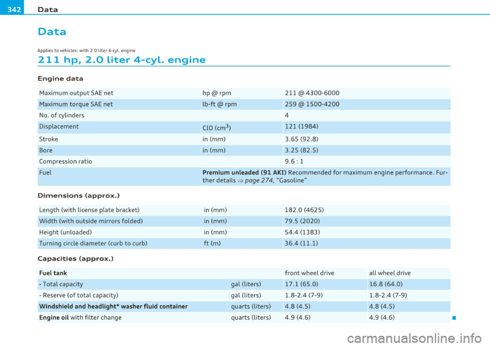
211 hp, 2.0 liter 4-cyl. engine
Engine data
Max imum outpu t SAE net
Max imum torque SAE net
No. of cy linde rs
Displacement
Stroke
Bore
Compression rat io
Fu el
Dimensions (approx .)
Length (with license plate bracket)
Width (with outside mirrors fol ded)
He ight (un loaded)
Turning circle d iameter (curb to curb)
Capacities (approx.)
Fuel tank
- Total capacity
- Reserve (of to tal c apaci ty)
Windshield and headlight * washer fluid container
Engine oil
with filter change hp@rpm
lb-ft@
rpm
C ID (cm
3
)
in (mm)
in (mm) 2
11 @ 4300- 6000
259@ 1500-4200
4
12 1 (198 4)
3.65 (92.8)
3.25 (82.5)
9 .6 : 1
Premium unleaded (91 AKI) R eco mmend ed for maximum engi ne per formanc e. Fur
ther details ~
page 274, "Gasoline"
in (mm)
in (mm)
i n (mm)
ft (m)
gal (Liters)
g al (Liters)
qua rts (liters)
quar ts (lite rs) 182
.0 (4625)
79 .5 (2020)
54.4 (1383)
36.4 (11. 1)
front wheel drive 17.1 (65.0)
1.8 -2.4 ( 7-9)
4.8 (4 .5)
4.9 (4.6) all whee
l drive
16.8 (64 .0)
1.8- 2.4 (7 -9)
4 .8 (4 .5)
4 .9 (4.6)
•
Page 345 of 364
______________________________________________ C _o_ n _ s_u_ m_ e_r_ I_n _f_ o_ r_m _ a_t_ i_ o _ n __ _
Consumer Information
Warranty coverages
Your Audi i s covered by the following warrantie s:
• New Vehicle Limited Warranty
• Limited Warranty Against Corrosion Perforation
• Emissions Control System Warranty
• Emissions Performance Warranty
• California Emissions Control Warranty (USA vehicles only)
• California Emissions Performance Warranty (USA vehicles only)
Detailed in forma tion reg ard ing yo ur war ran ties can be fo und in your
Warranty & Maintenance booklet .•
Operating your vehicle outside the
U.S.A. or Canada
Government regulations in the United States and Canada req uire that
au tomobile s mee t sp eci fic emi ssio n regula tions and safety s tan
dards . Therefore, vehicles b uilt for the U .S .A . and Canada d if f er from
vehicles sold in othe r countr ies .
If you plan to take your veh icle outs ide the con tinen tal lim its of the
United States o r Canada , there is the poss ibility that
• unle ade d fu els for veh icles wi th c atal ytic conve rter m ay no t be
available;
• fue l may have a conside rably lowe r octane rat ing. Im proper f ue l
may cause engine damage;
• serv ice may be inadeq uate due to lack of proper service facilities,
too ls o r testing eq uipment;
• replacemen t parts may not be read ily avai lab le .
Safety first
• N aviga tion syst ems for ve hicles built fo r th e U .S.A . and Canada
will not necessar ily work in Europe, and may not work in other coun
tr ies o utside of North America.
0 Note
Audi c annot be responsible for me ch anic al d am age t hat cou ld re su lt
from inadequate fuel, service or parts ava ilability. •
Audi Service Repair Manuals and
Literature
Audi Off icial Factory Service Manuals and L iterature are published as
soo n as po ssib le a fter m ode l intr oduc tion. Serv ice Ma nuals and li ter
ature are avai lable to order from the Audi Tech nica l Lite rature
O rd er in g Center at:
www.audi.techliterature.com •
Maintenance
General
Your vehicle has been desi gned to help keep main tenance re quire
ments to a minimum. Howeve r, a certa in amount of regular ma inte
n ance is s till necess ary to assure your ve hicle's sa fety, eco nomy and
reliab ility . For deta iled ve hicle maintenance co nsu lt yo ur Warranty
&
Maint enance booklet .
Under difficult operating conditions, for example at ext reme ly low
outs ide temperatures, in very dusty regions, when towing a trai ler
very freque ntly, etc., some se rv ic e w ork s hou ld be perf ormed
between the intervals speci fied . T hi s applies particular ly to: .,_
Do-it,yourself service Technical data