display AUDI A5 CABRIOLET 2011 Workshop Manual
[x] Cancel search | Manufacturer: AUDI, Model Year: 2011, Model line: A5 CABRIOLET, Model: AUDI A5 CABRIOLET 2011Pages: 364, PDF Size: 86.48 MB
Page 127 of 364
____________________________________________ A_ d_ a.:.p _t_ i_ v _e_ c_r_u _ i_ s _e_ c_o_ n_ t_r _o _l __ _
Appli es to ve hicl es: wi th a daptive cruise cont rol
System status indicator
The text messages and symbols shown in this area of the
display are not displayed permanently .
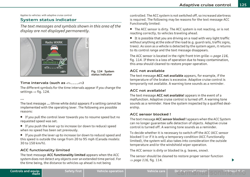
Time intervals (such as e::::, ____ e::::,)
Fig. 124 System
status indicator
The different symbols for the time intervals appear if you change the
sett ings => fig. 124 .
Th e text message ... (three white dots) appears if a setting cannot be
implemented with the operating lever. The following are possible
reasons:
• If you pull the control lever towa rds you to resume speed but no
requested speed was set .
• If you push the lever up to increase (or down to reduce) speed
when no speed has been set previously.
• If you push the lever up to increase (or down to reduce) speed and
this speed is outside the range from 20 to 95 mph (Canada mode ls:
30 to 150 km/h) .
ACC functionality Limited
The text message ACC functionality limited appears when the ACC
system does not detect any objects over an extended time period. For
the time being, the d istance to veh icles up ahead is not being
Controls and equip
ment Safety first
controlled
. The ACC system is not switched off, so increased alertness
is required. The following may be reasons for the text message ACC
Functionally limited:
• The ACC sensor is dirty. The ACC system is not reacting, or is not
reacting correctly, to vehicles traveling ahead.
• It is possible that you are driving on a road with very light traffic
without anything at the s ide of the road (e .g . guard rails, traff ic s igns,
trees). As soon as a vehicle is detected by the system again, it returns
t o its contro l range and the text message disappears.
The ACC sensor is located in the r ig ht front trim grille
=> page 116,
fig. 114 . If there is a loss of operation due to heavy contamination,
this area should cleaned to restore proper operat ion .
ACC not available
The text message ACC not available appears, for examp le, if the
t empe rature of the brakes is excessive. Adaptive cruise control is
temporarily not available. A warning tone sounds as a rem inder .
ACC not available!
The text message ACC not available! appears in the event of a
ma lf unct ion. Adaptive cruise control is turned off. A warn ing tone
sounds as a reminder . Have the system inspected by a qualified deal
ersh ip.
ACC sensor blocked !
The text message ACC sensor blocked ! appears when the ACC System
can no longer guarantee safe detection of objects. Adaptive cruise
control is turned off. A warning tone sounds as a reminder.
To decide whether it is necessary to switch off the ACC (ACC sensor
blocked
!) or if it is only a temporary condition (ACC Functionally
limited), the system w ill also takes into consideration the outside
temperature and/or the windshield wiper operation .
Th e ACC sensor is d irty or blocked (e.g. leaves, snow).
Th e sensor should be cleaned to restore prope r sensor funct ion
=> pagell6,fig.114.
Vehicle care Technical data
Page 128 of 364
BI..__A_ d_a_ p,__ t_iv _ e_ c_r _ u _i _ s _e _ c_o _n _ t_ r_ o_ l ___________________________________________ _
Parking brake!
The text message Parking brake! appears if emergency braking was
manually initiated with the Electromechanical Parking Brake (EPB).
The adapt ive cruise control is turned off. This is accompanied by a
warning tone.
Stabilisation program
The text message Stabilisation program appears if the Elect ronic
Stabilization Program (ESP) has intervened. In this case the adaptive
cruise control is automat ica lly turned off. This is accompanied by a
warning tone.
Speed
The set speed in mph (Canada km/h) always appears when saving or
changing the speed in adaptive cruise control~
page 119, "How is
the speed stored?" and~
page 119, "Changing stored speed".
Speed too low
The text message Speed too low appears if the current speed is too
low
to set or to hold the requested speed.
When setting a desired speed, it must be at least 20 mph (30 km/h).
At speeds below 12 mph (20 km/h), the cruise control is turned off .
In speeds over 95 mph (150 km/h), the system remains active and
resumes the speed of 95 mph (150 km/h) if the driver removes the
foot from the accelerator .
Selector lever position!
The text message Selector lever position! appears when the selector
lever is moved to position
N. In this position , adaptive cruise control
is not available .•
A pplie s to veh icles : wit h adap tive cru ise contro l
Driver intervent ion prompt
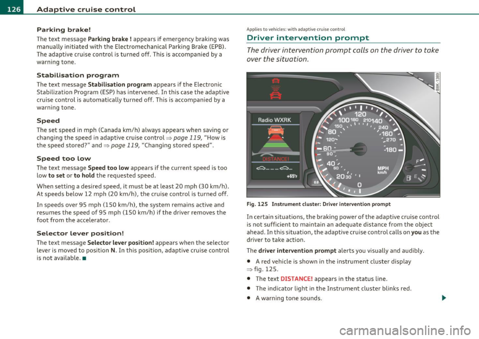
The driver intervention prompt calls on the driver to take
over the situation .
Fig. 125 Instrument cluster: Driver intervention prompt
In certain situations, the braking power of the adaptive cruise control
is not sufficient to maintain an adequate distance from the object
ahead . In th is s ituation, the adaptive cruise control calls on you as the
driver to take action.
The
driver intervention prompt alerts you visua lly and audibly.
• A red vehicle is show n in the instrument cluster display
=> fig . 125.
• The text
DISTANCE! appears in the status line .
• T he indicator light in the Instrument cluste r blinks red.
• A warning tone sounds.
Page 131 of 364
____________________________________________ A_ d_ a___,_ p_t_ i_v _e _ c_r _u _ i_ s _e _ c_o _ n_ t_r _o _l _ __.ffl'I
A pp lies to vehicl es : wi th a daptiv e cr uise c ontro l
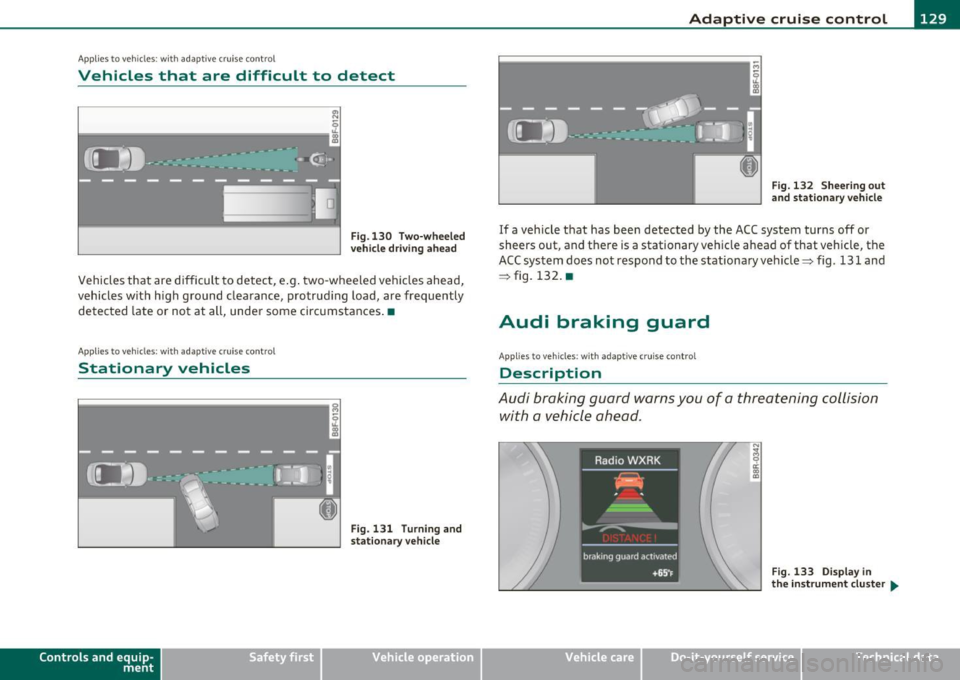
Vehicles that are difficult to detect
OJ
Fig .130 Two-wheeled
vehicle driving ahead
Vehicles that are difficult to detect, e .g . two-wheeled vehicles ahead,
vehicles with h igh ground clearance, protrud ing load, are frequently
detected late or not at all, under some circumstances .•
A ppli es to ve hicl es: with ad apti ve c rui se cont rol
Stationary vehicles
k-----------------· g
Con tro ls a nd e quip
m en t
;
Fig. 131 Turn ing and
stat ionary v ehicle
Vehicle OP-eration
Fig. 132 Sheering out
and stationary vehicle
If a vehicle that has been detected by the ACC system turns off or
sheers out, and there is a stationary veh icle ahead of that vehicle, the
ACC system does not respond to the stationary vehicle=> fig. 131 and
=> fig. 132. •
Audi braking guard
Applies to vehicles: with ada ptiv e cr uise con trol
Description
Audi braking guard warns you of a threatening collision
with a vehicle ahead .
N
I
Fig. 133 Display in
the in strum ent cluster ...
Vehicle care Do-it-yourselt service iTechnical data
Page 132 of 364
IIII.___A_ d_ a,.:.p _ t_ i _v _ e_ c_ r _u _ is_ e_ c_o _n_ t_r _o _l _____________________________________________ _
The Audi braking guard is active from a speed of approx. 20 mph
(30 km/h) and works within the system limits=>
page 12 7 even when
the adaptive cruise control is deactivated.
A radar sensor is built into the front of the vehicle=>
page 116,
fig. 114. The system is intended to measure the distance to reflective
surfaces. If a measurement is not possible, the system does not
respond.
When the measurement has taken place, the system can assess a
hazardous situation, when a vehicle ahead suddenly brakes or when
your own vehicle is dr iving at high speed towards a much slower
vehicle ahead. As soon as the system assumes that a possible colli
sion w ith the vehicle ahead can only be avoided by immediate all-out
braking or by an avoiding maneuver, a warning appears .
Th e system has a pre-set response time to be able to warn in good
time. This system response time is automatically reduced if you accel
erate actively, for example to join a highway. Braking, transverse
acceleration and the steering angle can lead to a reduced system
response time. The warning is deactivated if you begin to overtake
with full accelerat ion.
The system draws your attention to two different hazardous situa
tions:
Distance
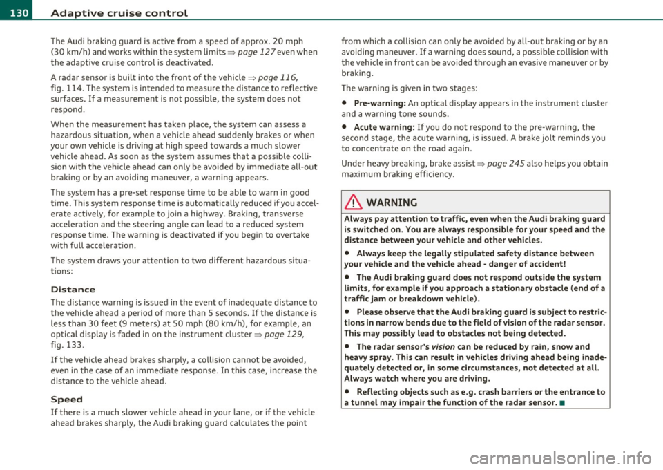
Th e distance wa rning is issued in the event of inadequate distance to
the vehicle ahead a period of more than S seconds. If the distance is
less than 30 feet (9 meters) at SO mph (80 km/h), for example, an
optical display is faded in on the instrument cluster=>
page 129,
fig. 133.
If the vehicle ahead brakes sharply, a collision cannot be avoided,
even in the case of an immediate response. In this case, increase the
distance to the vehicle ahead.
Speed
If there is a much slower vehicle ahead in your lane, or if the vehicle
ahead brakes sha rply, the Audi braking guard calculates the point from which a collision can only be avoided by all-out braking or by an
avoiding maneuver. If a warning does sound, a possible collision with
the vehicle in front can be avoided through an evasive maneuver or by
braking.
Th e warn ing is given in two stages:
• Pre-warning: An optical display appears in the instrument cluster
and a warning tone sounds.
• Acute warning: If you do not respond to the pre-warning, the
second stage, the acute warning, is issued. A brake jolt reminds you
to concentrate on the road again.
Under heavy breaking, brake assist =>
page 245 also helps you obtain
maximum braking effic ien cy.
& WARNING
Always pay attention to traffic, even when the Audi braking guard
is switched on. You are always resp onsible for
your speed and the
distance between your vehicle and other vehicles.
• Always keep the legally stipulated safety distance between
your vehicle and the vehicle ahead -danger of accident!
• The Audi braking guard does not respond outside the system
limits, for example if you approach a stationary obstacle (end of a
traffic jam or breakdown vehicle).
• Please observe that the Audi braking guard is subject to restric
tions in narrow bends due to the field of vision of the radar sensor.
This may possibly lead to obstacles not being detected.
• The radar sensor's
vision can be reduced by rain, snow and
heavy spray . This can result in vehicles driving ahead being inade
quately detected or, in some circumstances, not detected at all.
Always watch where you are driving.
• Reflecting objects such as e.g. crash barriers or the entrance to
a tunnel may impair the function of the radar sensor.•
Page 133 of 364
Adaptive cruise control -____________ __._ __ _
App lies to ve hicl es: wi th a daptive cruise co ntro l
Settings in the MMI
The settings of the Audi braking guard are performed in
the MMI* .
Settings regarding the system and the early warning can be
adjusted to the respective user and saved in the MM!*.
Switching the syst em on and off
- Press the [CAR]function button .
- Select
Audi brak ing guard . The Audi b raking gua rd menu
appears.
- Select
System on to switch the system on or off to switch
the system off .
Switching the early warning on and off
- Press the [ CAR] function button .
- Select
Audi braking guard . The Audi braking guard menu
appea rs .
- Select
Early warning on to switch the acoustic and optical
warning on or
off to switch the system off .
(I) Tips
When handing over the keys to another person , the p revious settings
are adopted if the Audi braking guard is activated~
page 43. •
Controls and equip
ment Safety first
A
pp lies to ve hicles : w ith ada ptiv e cr uise cont ro l
Driver's information in the instrument
cluster display
braking guard ac tiv at ed
This driver's information appears when a brake jolt has been carried
out due to an acute war ning .
brak ing guard off
T his dr iver's info rmation appears when the system has been deacti
vated via the MMI. Furthermore the information appears each t ime
shortly after the beginning of the jou rney when the system is
switched off.
T his driver's information also appears when the system is not avai l
able due to a malfunct ion or if you switch the ESP/ ASR off
~ page 240. In this state the system no longer warns of a pending
collision .•
Vehicle care Technical data
Page 135 of 364
Audi lane assist ml
----------------
Not ready: The yellow indicator light shows that the system is
turned on but unable to send a warning. This can be due to the
following:
• Th ere are no boundary lines, or there is only one boundary line
present.
• The boundary lines are not detected (e .g . due to snow, dirt, wet
conditions or light shining into the camera lens).
• More than two boundary lines (such as at construction sites) are
located in the vehicle's lane.
• Th e vehicle's speed is below the speed needed to activate it, which
is about 40 mph (65 km/h) .
• Th e lane is narrowe r than about 8
ft. (2.5 m), or wider than about
16 ft. (5 m).
• The curve is too sharp.
Notes on the instrument cluster display
When the lane assist turns off automatically, the instrument cluster
indicator goes out and one of the fo llowing messages appears on the
display:
Audi lane assist not available: currently no sensor vision
This message appears when the camera can no longer function
because it cannot detect the boundary lines. This may be due to the
following:
• Th e exte rior side of the camera viewing window=>
page 132,
fig. 135 is covered with dirt or ice. Clean this part of the windsh ield.
• Th e came ra viewing window is fogged up on the inside. In this
case, wait until the fog disappears before turning lane assist on
again.
• Th e system was unable to detect boundary lines over an extended
period of time due to road conditions (such as snow-cove red lanes).
Do not turn lane assist on aga in until the lines can be more easily
detected.
Audi lane assist currently not available
Controls and equip
ment Safety first
A temporary malfunction
is preventing lane assist from operating .
Tr y turning on lane assist again at a lat er time.
Audi lane assist: system fault
The system shou ld be checked by an authorized Audi dealer or other
qualified wo rkshop.
[ i ] Tips
• Make sure that the camera viewing window =>
page 132, fig. 135
is not covered by stickers or similar objects.
• Always keep the camera viewing w indow clean. This can us ually be
done by operating the windshie ld wipers. •
Applies to ve hicles : with lane assist and trip comp ute r
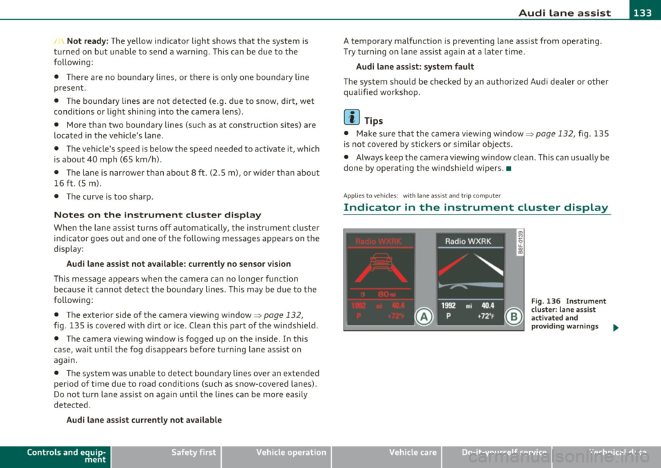
Indicator in the instrument cluster display
Vehicle care
Fig. 136 I nstrument
cluster: lane assist
ac tiva ted and
provid in g warning s ...
Technical data
Page 136 of 364
1111....__A_ u_ d_i_ l_ a_ n_ e_ a_s_ s_ is_t _________________________________________________ _
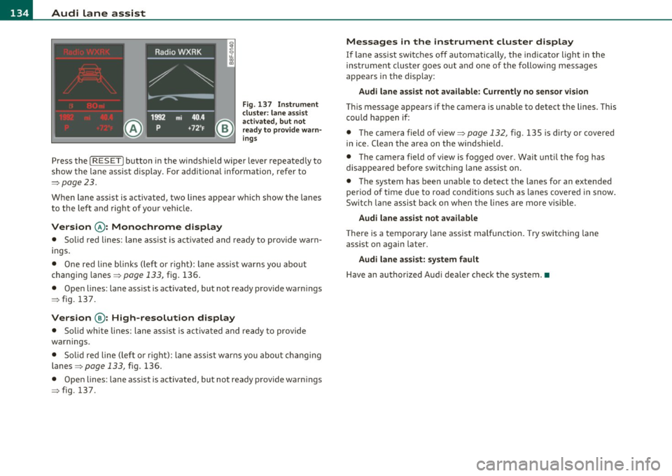
Fig. 137 Ins trume nt
clu ster : lane assis t
ac tiv ated , bu t n ot
ready to provid e warn
ing s
Press the [ RESET] button in the winds hield wipe r lever repeated ly to
show the lane assist display . For ad ditiona l information, refer to
:::>pag e 23.
When lane assist is activated, two lines appear which show the lanes
t o the le ft and right of yo ur vehi cle.
Version @ : Monochrome display
• Solid red lines: lane ass ist is activa ted and ready to prov ide war n
ings.
• One red line bli nks (left or r ight) : lane ass ist warns you abou t
changin g lanes =>
page 133, fig. 136 .
• Open lines: lane assist is activated, but not ready provide warn ings
=> fig. 137 .
Version @: High-resolution display
• Solid whi te lines: lane ass is t i s activa ted and ready to p rovide
wa rnings.
• Solid red line (left o r rig ht): lane ass ist w arns you about changi ng
lanes=>
page 133, fig. 136.
• Ope n lines: lane assist is activated, but no t ready p rovide warn ings
=> fig. 137.
Messages in the instrument cluster display
If lane assis t sw itches o ff automatically, the indicator light in the
ins tru men t cluste r goes ou t and one of the following messages
appears in the disp lay:
Audi lane as sist not available: Currently no sensor vi sion
T hi s message appears if t he camera is unab le to detect the lines. This
c o uld h appen i f:
• Th e came ra field of view=>
page 132, fig. 135 is dirty or covered
in ice. Clean the area on the windshie ld.
• Th e came ra field of vi ew is fogged over . Wait unt il the fog has
disappea red befo re switching lane assist on .
• The system has been unable to detect the lanes for an extended
period of time due to road cond it ions s uch as lanes covere d in snow .
Switch la ne assist back on when the li nes are mo re vis ible.
Audi lane assist not available
Th ere is a temporary lane assist malfunction. Try switching lane
assist on again later.
Audi lane assist: system fault
H ave an au thor ized A udi deale r check the syste m.•
Page 143 of 364
_________________________________________________ A_ u _ d_ i_ s_ id_ e_ a _ s_s _ i_s _t _--J_
A pplie s to ve hicles : wi th s id e ass ist
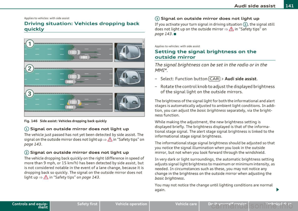
Driving situation: Vehicles dropping back
quickly
@
I
- (OIDJ -
•. _ ...
' I
- Q•n
-~---
Fig. 146 Side assist: Vehicles dropping back quickly
(D Signal on outside mirror does not light up
The vehicle just passed has not yet been detected by side assist. The
signal on the outside mirror does not light up~
& in "Safety tips" on
page 143.
@ Signal on outside mirror does not light up
The vehicle dropping back quickly on the right (difference in speed of
more than 9 mph, or 15 km/h) has been detected by side assist, but
is not considered notable in the event of a lane change, because it is
dropping back so quickly . The signal on the outside mirror does not
light up~
& in "Safety tips" on page 143.
Con tro ls a nd e quip
m en t Vehicle
OP-eration
® Signal on outside mirror does not light up
If you activate your turn signal in driving situation @, the signal still
does not light up on the outside mirror~
& in "Safety tips" on
page 143. •
App lies to ve hicles : with side assis t
Setting the signal brightness on the
outside mirror
The signal brightness can be set in the radio or in the
fv1fv1I*.
- Select: Function button I CAR] > Audi side assist.
- Rotate the control knob to adjust the displayed brightness
of the signal Light on the outside mirrors.
The brightness of the signal light for both the informational a nd alert
stages is automatically adjusted to ambient light conditions. In addi
tion, you can adjust the
basic brightness separately, via the bright
ness function.
While making the adjustment, the new brightness setting is
displayed briefly. The brightness displayed is that of the informa
tional stage signal. The alert stage signal brightness is linked to the
informational stage signal brightness.
The informational stage signal brightness should be adjusted so that
you notice the signal illumination when you look in the outside
mirror, but not when you look forward through the windshield .
In very dark or light surroundings, the automatic brightness setting
adjusts signal light brightness to maximum or minimum intensity, as
needed. In circumstances such as these, you may not notice any
change in the brightness on the outside mirror when adjusting the
basic brightness.
You may not notice the change until lighting conditions are normal
again.
Vehicle care Do-it-yourselt service iTechnical data
Page 145 of 364
_________________________________________________ A_ u_d _ i_ s_id _ e_ a_s _s_ i_s _t __ _
Notes
Applies to veh icles: w ith s ide ass ist
Messages in instrument cluster display
If side assist turns off automatically, the indicator lig ht on the butto n
w ill go out and yo u w ill see a message in the instrument cl uster
display:
Audi side assist not available: sensors blocked
Th e side ass ist senso rs a re b uilt in to the rear bum per o n the left and
r ight (not v is ible on the outside)=>
page 136, fig. 139. To e nsure
that you do not adve rsely affect the way side assist f unctions, foreign
objec ts (such as stic ke rs or b icycle racks) should not be attached to
the a rea on the rear bumper where t he sensors are located. If side
as sis t fu nctions a re adverse ly affe cted , you will see thi s me ssa ge in
the instrume nt cl uster disp lay. Remove anything that may b e
bl ockin g the sensor s.
If no ve hicle is detected for a lo nger p eriod of t ime w hile driving, side
assist w ill also switch off automatically .
Audi side assist currently not available
If the re is a te mp orary p rob lem (such as the vehicle 's batt ery ch arg e
bei ng low) , side assist ca nnot be act ivated temporar ily.
Audi side assist : system fault
Have the system checked by an auth orized Audi dealer or qualified
wo rkshop .•
Applies to veh icles: w ith s ide ass is t
Safety tips
T he side assist detect io n may be limited when driving a ro u nd na rrow
s tr ee t co rner s, on hilly stree ts, and und er poor we ather cond itio n s.
Controls and equip
ment Safety first
It
is possible that the rada r senso rs may a lso detect o ther objects,
such a s high or stag gere d guar drails.
S ide assis t does not measure actua l lane w idth. The system assum es
a fi xed la ne w idt h. Detection in the left and right lanes is based on
t hi s a ssumed lane w id th. Wh en driving o n narrow ro ads or w he n
dr iv ing to the left or rig ht of the center of a travel lane, it is poss ible
t h at vehicles will be de tected tha t a re
no t in th e lan e nex t to th e l an e
you are using.
& WARNING
• Improper reliance on the side assist system can cause collisions
and serious personal injury:
-Never rely only on side assist when changing lanes .
- Always check rear view mirrors to make sure that it is safe to
change lanes.
• Side assist cannot detect all vehicles under all conditions
danger of accident!
• Side assist cannot detect vehicles in time to alert you when
they approach from behind at very high speed , or fall drop back
very quickly .
• The radar sensor's
vision can be reduced or entirely blocked by
rain, snow, and heavy spray. This can result in side assist not
adequately detecting vehicles or, in some cases , not detecting
them at all. Always keep an eye on the direction you are traveling and the relevant area around the vehicle .
• Please note that side ass ist indicates there are approaching
vehicles, or vehicles in your blind spot, only after your vehicle has reached a driving speed of at least 19 mph (30 km/h).
• Side assist signal does not work around tight corners (turning
radius less than 328 feet, or 100 m ).
• Side assist is no replacement for the driver's full attention . The
driver alone is responsible for lane changes and similar driving
maneuvers. Always keep an eye on the direction you are traveling
and the relevant area around the vehicle. .,,
Vehicle care Technical data
Page 151 of 364

____________________________________________________ T_r_a _ n_ s_m_ i_ s _s_ i_ o _ n __ _
The selector lever must be in Nor P . If one o f the dr iv in g positions is
e n gag ed a saf ety s witch will preven t the engin e from b eing sta rt e d.
S ee also=>
page 106.
Be fore you move t he se lecto r lever from t he P position, yo u m ust
a lw ay s a ppl y the b rake pedal before and while depr ess ing the bu tton
in t he handle of the selector lever.
_& WARNING
• Unintended vehicle movement can cause serious injury.
- When the selector lever is
in a driving position, the vehicle
may creep, even at idle speed. Therefore do not release the
parking brake
or foot brake until you are ready to move,
because power is transmitted to the wheels as soon as a driving
position is engaged.
- Do not accelerate while selecting a driving position . At this
time the engine must be at idle speed so that undue stress is
not placed on the clutches in the transmission.
- Remember : · even when stopped briefly with the automatic
transmission
in " D", "S" or "R", engine power is being trans
mitted to the wheels. Your vehicle could "creep " forward or
backward. When stopped, keep the brake pedal fully
depressed and use the parking brake if necessary to keep the
vehicle from rolling .
• If the selector lever is unintentionally moved into N while you
are driving, take your foot off the accelerator pedal and wait for
the engine to return to idle speed before selecting a driving posi
tion.
• Never shift into "R" or "P " when the vehicle is in motion .
• Never get out of the d river's seat when the engine is running.
• If you must get out of the vehicle , move the selector lever
securely into the P position and apply the parking brake firmly .
• If the engine must remain running, never have any driving
position engaged when checking under the hood. Make sure the
selector lever has securely engaged and is locked in "P " with the
Controls and equip
ment Safety first
& WARNING (
cont inued)
parking brake firmly set=> page 272, "Engine compartment ".
Otherwise, any increase in engine speed may set the vehicle in
motion, even with the parking brake applied. •
App lies to vehicles : w it h auto mat ic t ransmiss ion
Selector lever positions
T his s ection d escrib es the s ele ct or l eve r posi tions and
drivin g ran ges.
Fig. 152 Di splay in
the instrum ent cluster:
selector lever In posi
tio n P
Th e sele ctor lever posi tion engaged appe ars ne xt to the se le ct or lever
as well as in the instr umen t cluster display .
P -Park
In this selector lev er position the transmiss ion is mecha nica lly
l oc ked. Engage
P only when the vehi cle is comple tely sto pp ed=> &
in " Driving t he automatic transmiss io n" on page 148.
T o sh ift in o r o ut of position P , yo u must first press an d hold the brake
peda l
and th en press t he r elease b utton in t he se lec to r l eve r hand le
wh ile moving the selector lever to or from
P. Yo u can s hif t out of thi s
posit ion on ly with t he ignit ion on . .,,
Vehicle care Technical data