sensor AUDI A5 CABRIOLET 2013 Owner's Manual
[x] Cancel search | Manufacturer: AUDI, Model Year: 2013, Model line: A5 CABRIOLET, Model: AUDI A5 CABRIOLET 2013Pages: 290, PDF Size: 72.35 MB
Page 113 of 290
_& WARNING
-Sensors have dead spaces in which ob
jects cannot be detected. Be especially
alert for small children and animals,
since they are not always detected by the
sensors.
- The acoustic park ing system is not a sub
st itute for the driver 's own caution and
alertness. Ultimate responsibi lity always
remains with the driver during parking
and simi lar maneuvers . Always watch
where you are driving.
- You should always adjust the volume and
frequency of the warning tones so that
yo u can easily hear the acoustic distance
warning even if the radio is p laying, the
air-cond itioner blower is on High or there
is a high level of outside noise .
- Check the settings whenever anyone
else has driven the vehicle before you.
(D Note
-Remember that low obstacles for which
a warn ing has already been issued may
"dive" below the system's sensing zone if
the vehicle is being backed up closer. In
this case, the warning sound shutting off
does
not in dicate that you have cleared
the obstacle . Instead, impact is immi
nent.
- Objects such as trailer hitches, chains,
narrow posts or fences covered by a th in
l ayer of paint may not always be detect
ed by the system. They can still damage
your vehicle without warning .
@ Tips
Keep the sensors in the rear bumper clean
and free of snow and ice so that the acous
tic parking assist system can function
properly.
Park assist 111
Adjusting the warning tones
Applies to vehicles: with parking system (rear)
The warning tones can be adjusted in the
MM!*.
.. Select: I CAR ! function button > Parking sys
tem .
Or
.. Select:
I CAR I function button > Car sys
tems *
control button > Driver assist > Park
ing aid .
- Rear volume -
rear sensor volume
-Rear frequency -rear sensor frequency
-Music volume while parking -when the
parking system is switched on, the volume
of the active audio source is lowered.
The newly ad justed value is briefly heard from
the signal generator. The settings are auto
matically stored and assigned to the master
key with remote control.
Parking system (rear,
with rear view camera)
Introduction
Applies to vehicles: with parking system (rear, with rear
v iew camera}
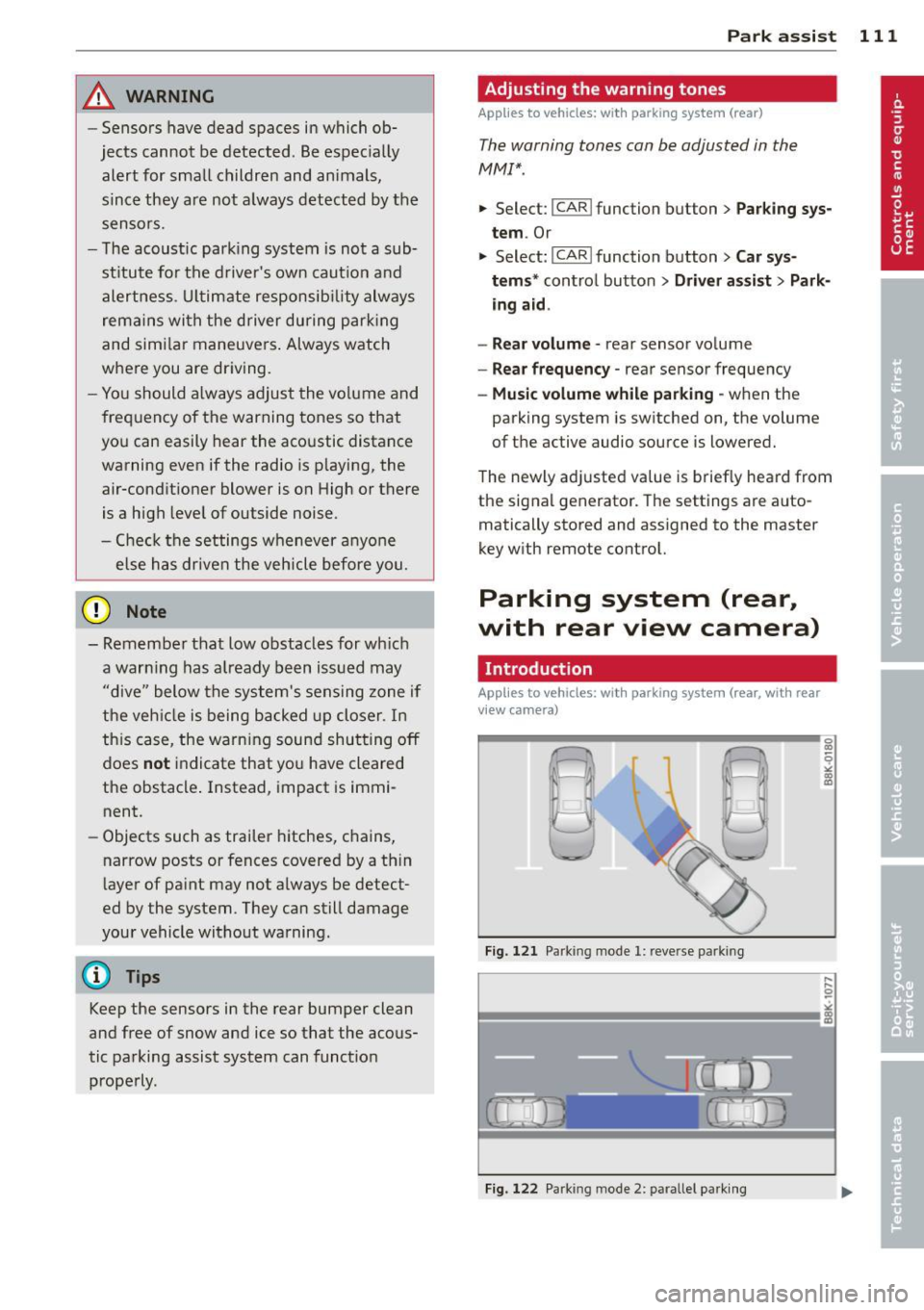
Fig. 121 Parking mode 1: reve rse park ing
Fig. 122 Park ing mode 2: parallel parking
Page 114 of 290
112 Park assist
Vehicles with the parking system are equipped
with a rear view camera in addition to the
acoustic parking system.
You can choose between two modes to assist
you with parking. For example, you can use
"parking mode 1" when parking in a parking
space or garage
c;;, fig . 121. When you want to
park parallel to the edge of the street, select
"parking mode 2" ¢fig .
122.
The rear acoustic park assist system is inte
grated in the rear of the vehicle and the rear
view camera is integrated in the rear lid
c;;, page 113.
A WARNING
- T he rear view camera has blind spots, in
wh ich objects cannot be detected . Be es
pecially careful to check for small chil
dren and animals before backing up.
Small children and animals will not al
ways be detected by the sensors.
General Information
Applies to vehicles: with parking system (rear, with rear
view camera)
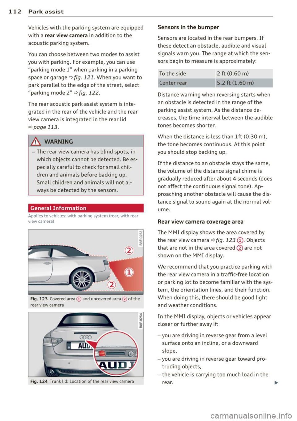
Fig. 123 Cove red area (!) and uncovered area @ of the
rea r view came ra
F ig. 124 Trun k lid : Location of the rear view camera
Sensors in the bumper
Sensors are loca ted in the rear bumpers. If
these detect an obstacle, audible and visual
signals warn you. The range at which the sen
sors begin to measure is approx imately:
To the side 2
ft (0.60 m)
Center rear 5.2 ft (1.60 m)
Distance warning when reversing starts when
an obstacle is detected in the range of the parking assist system . As the distance de
creases, the time interval between the audible
tones becomes shorter.
When the distance is less than 1ft (0.30 m),
the tone becomes continuous. At this point
you should stop backing up.
If the distance to an obstacle stays the same,
the volume of the distance signal chime is
gradually reduced after about 4 seconds (does
not affect the contin uous signa l tone) . Ap
proaching another obstacle will cause the dis
tance signal to sound again at the normal vol
ume.
Rear view camera coverage area
The MMI display shows the area covered by
the rear view camera
c:> fig. 123 (D . Objects
that are not in the area covered @are not
shown on the MMI display .
We recommend that you practice parking with
the rear view camera in a traffic-free location
or parking lot to become familiar with the sys
tem, the orientation lines, and the ir function.
When doing this, there should be good light
and weathe r cond itions.
In the MMI display, objects or vehicles appear
closer or further away if:
- you are driving in reverse gear from a leve l
surface onto an incline, or a downward
slope,
- you are driving in reverse gear toward pro
trud ing objects,
- the vehicle is carrying too much load in the
rear.
Page 116 of 290
114 Park assist
@ Tips
-The rear view camera picture is available
as soon as the MMI Display or the MMI is
switched on, or the start-up phase is
completed.
- Keep the sensors in the rear bumper and
the rear view camera lens clean and free
of snow and ice, so that the parking sys
tem can work properly. Please follow the
additional notes on
~page 116.
Reverse Park ing
Appl ies to vehicles: with parking system (rear, wit h rear
view came ra)
Parking mode 1 can be used when parking in
a garage or parking space.
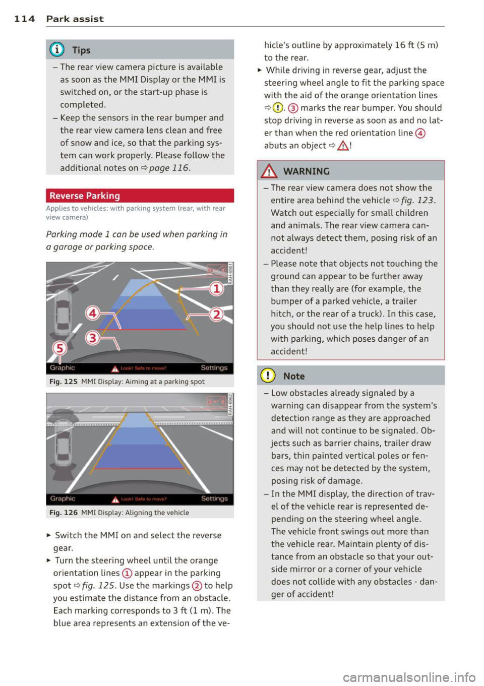
Fig. 125 MMI Display : Aiming at a parking spot
Fig. 126 MMI Display: Alig ning the vehicle
"' Switch the MMI on and select the reverse
gear.
"' Turn the steering wheel until the orange
orientation lines
(D appear in the parking
spot ¢
fig. 125 . Use the markings @to help
you estimate the distance from an obstacle .
Each marking corresponds to 3
ft (1 m) . The
blue area represents an extension of the ve- hicle's outline by approximately
16
ft (5 m)
to the rear.
"' While driving in reverse gear, adjust the
steering wheel angle to fit the parking space
with the aid of the orange orientation lines
¢ 0 . @ marks the rear bumper . You should
stop driving in reverse as soon as and no lat
er than when the red orientation line©
abuts an object¢_&. !
_& WARNING
-The rear view camera does not show the
entire area behind the vehicle
¢ fig. 123.
Watch out especially for small children
and animals. The rear view camera can
not always detect them, posing risk of an
accident!
- Please note that objects not touching the
ground can appear to be further away
than they really are (for example, the
bumper of a parked vehicle, a trailer
hitch, or the rear of a truck). In this case,
you should not use the help lines to help
with parking, which poses danger of an
accident!
(D Note
- Low obstacles already signaled by a
warning can disappear from the system's detection range as they are approached
and will not continue to be signaled. Ob
jects such as barrier chains, trailer draw
bars, thin painted vertical poles or fen
ces may not be detected by the system,
posing risk of damage.
- In the MMI display, the direction of trav
el of the vehicle rear is represented de
pending on the steering wheel angle.
The vehicle front swings out more than
the vehicle rear . Maintain plenty of dis
tance from an obstacle so that your out side mirror or a corner of your vehicle
does not collide with any obstacles -dan
ger of accident!
Page 118 of 290
116 Park assist
In the MMI display, the direction of travel
of the vehicle rear is represented depending on the steering wheel angle. The vehi
cle front swings out more than the vehicle
rear. Maintain plenty of distance from an
obstacle so that your outside mirror or a
corner of your vehicle does not collide with
any obstacles -danger of accident!
@ Tips
The left or right orientation lines and sur
faces will be displayed, depending on the turn signal being used.
Adjusting the display and warning tones
Applies to vehicles: with parking system (rear, with rear
view camera)
The display and warning tones are adjusted in
the radio or MM!*.
"' Select: I CARI function button > Parking sys·
tern.
Or
"' Select: ~I C~A~RI function button > Car sys
tems*
control button > Driver assist > Park·
ing aid.
Display
- Off -when the parking system is switched
off, only audible signals are given.
- On -when the parking system is switched
on, the picture from the rear view camera is
displayed.
Warning tones
- Rear volume -
rear sensor volume
-Rear frequency -rear sensor frequency
-Music volume while parking -when the
parking system is switched on, the volume
of the active audio source is lowered.
The newly adjusted value is briefly heard from
the signal generator. The settings are auto
matically stored and assigned to the remote
control key.
A WARNING
- Always make sure that the volume and
frequency of the warning tones is adjust
ed so that you can easily hear the acous
tic distance signal even if the radio is
playing, the air-conditioner blower is on
High or there is a high level of outside
noise.
- Check the settings whenever someone
else has driven the vehicle before you.
@ Tips
- The warning tones can also be adjusted
directly from the rear view camera im
age. Simply press the Settings* control
button.
- Changed settings are activated when
parking assist is switched on again.
Error messages
Applies to vehicles: with parking system (rear, with rear
view camera)
-
If a warning tone is audible for about five sec
onds when you turn on the ignition, there is a
malfunction in the system. Have the problem
corrected by your authorized Audi dealer.
Keep the sensors in the rear bumper clean and
free from ice so that the acoustic park assist system can function properly.
Page 119 of 290
Homelink®
Universal remote
control
Description
Applies to vehicles: with Home link
The HomeLink universal remote control con
be programmed with the remo te control for
devices that ore already present.
With Home Link, you can control devices such
as the garage door, secu rity systems, ho use
lights , etc. comfortably from the inside of you
veh icle .
H omelink makes it poss ible for you to rep lace
t hree different remote controls from dev ices
in your home with one un ive rsal remo te. Th is
featu re works for most garage door and exte
rior door motor signals. Programming the in
d ividual remote control for your remote con
trol takes p lace near the center of the radiator
grille. There is a control module attached at
this location .
A one-t ime programm ing of the sensor must
be performed before you are able to use sys
tems with Homelink. If the system does not activate after performing the one-t ime pro
gramming, check whether the system uses a rolling code
¢ page 120 for veh ides without
the MMI*.
& WARNING
-
-Never use the Homelink ® transmi tter
with any garage door opener that does have not the sa fety stop and reverse fea
ture as requ ired by federa l safety stand
ards. Th is includes any garage door open
er mode l manufactured before April 1,
1982.
- A garage door opener which cannot de
tect an object, signaling the door to stop
and reverse does not meet current feder
al safety standards . Us ing
a garage door
opener without these features increases
r isk of serious inj ury or death.
Homelink ® 11 7
-For safety reasons never re lease the
parking brake or start the eng ine while
anyone is standing in front of the vehicle .
- A garage door or an estate gate may
sometimes be set in motion when the
Homelink ® remote control is being pro
grammed. If the device is repeatedly ac
tivated, th is can overstrain motor and
damage its e lectrical compon ents -an
overheated mo to r i s
a fire hazard!
- To avo id possib le injuries or property
damage, please always make abso lutely
certa in that no person s or objects are lo
cated in the range of motion of any
equ ipment being operated .
(0 Tips
-If you would like more information on
Homelink ®, where to purchase the
Home link ® compatib le products, or
would like to purchase the Homelink ®
Home Lighting Package, please ca ll toll
free: l-800-355-3515.
- For Declaration of Compliance to United
States FCC and Industry Canada reg ula
tions ¢
page 2 72.
- For security reasons, we recommend that
you clear the programmed b uttons be
fore selling the veh icle.
Operation
App lies to vehicles : with Homeli nk
Fig . 1 29 Head li ner: controls
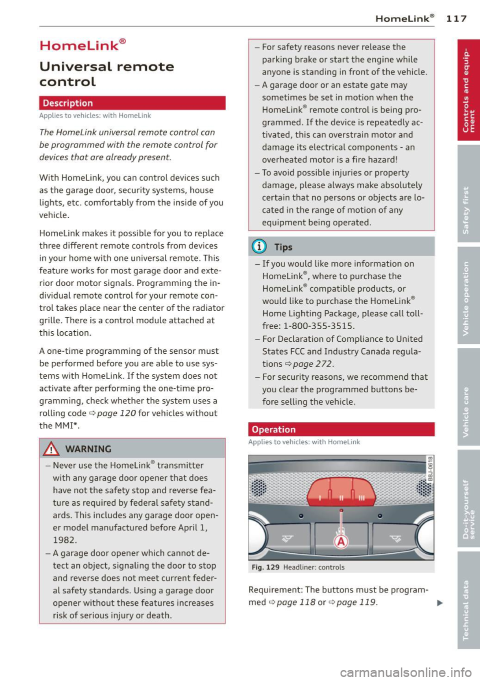
Req uirement : The buttons must be program-
med
c!) page 118 or ¢ page 119. ..,_
Page 132 of 290
130 Driving Safely
Tel.: 1-800-333-0510 or
Tel.: 1-819-994-3328 (Ottawa region and from other coun
tries)
TTY for hearing impaired: Tel.:
1-888-675-6863
or contact Transport Canada by
mail at:
Transport Canada Motor Vehicle Safety Investiga
tions Laboratory 80 Noel Street
Gatineau, QC
J8Z 0Al
For additional road safety infor
mation, please visit the Road
Safety website at:
http:/ /www.tc .gc.ca/eng/
roadsafety/menu. htm
Active rollover
protection system
Function
The rollover protection system helps protect
vehicle occupants in the event of a rollover.
l '1
I j 1 !
I i I
Fig. 135 Rear seats: Rollbar deplo yment ra nge
Fig. 136 Rear seats: rollbar deploye d
; 0 ii. II) ID
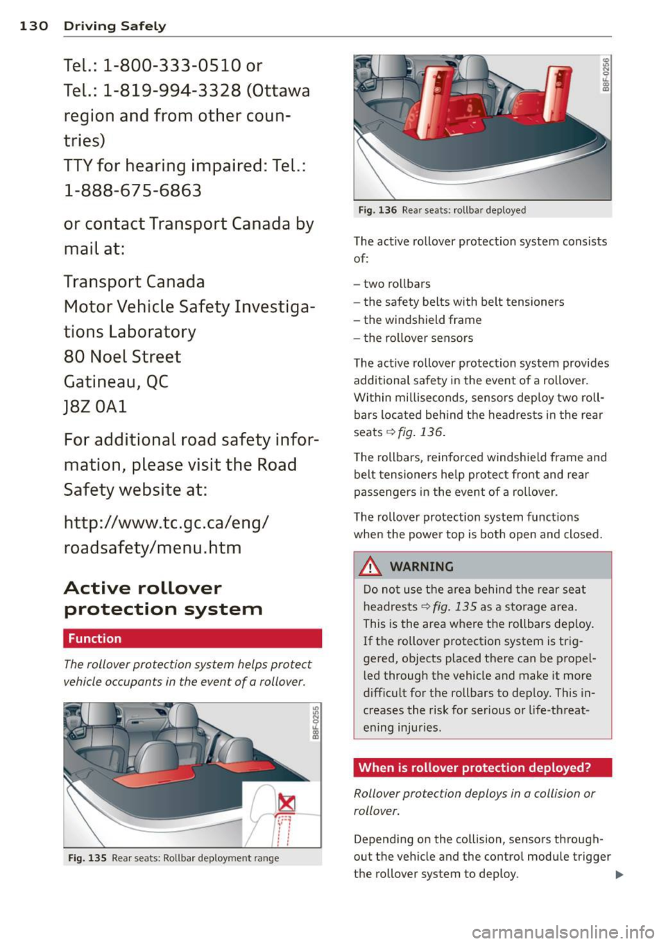
The active rollover protection system consists
of:
- two rollbars
- the safety belts with belt tensioners
- the windshield frame
- the rollover sensors
The act ive rollover protection system provides
additional safety in the event of a rollover.
Within milliseconds, sensors deploy two roll
bars located behind the headrests in the rear
seats r:!)fig.
136.
The rollbars, reinforced windshield frame and
belt tensioners help protect front and rear
passengers in the
event of a rollover.
The rollover protection system functions
when the power top is both open and closed.
A WARNING
Do not use the area behind the rear seat
headrests
I:!) fig. 135 as a storage area.
This is the area where the rollbars deploy.
If the rollover protection system is trig
gered, objects placed there can be propel
led through the vehicle and make it more
difficult for the rollbars to deploy. This in
creases the risk for serious or life-threat
ening injuries.
When is rollover protection deployed?
Rollover protection deploys in a collision or
rollover.
-
Depending on the collision, sensors through
out the vehicle and the control module trigger
t he rollover system to deploy.
ll>-
Page 149 of 290
-Always move the passenger seat into its
rearmost position in the seat's fore and
aft adjustment range, as far away from
the a irbag as poss ible, before insta lling
the forward-facing child restraint. The backrest must be adjusted to an upr ight
posit ion.
- Make sure that the
PASSENGER AIR BAG
OFF
light comes on and stays on all the
t ime w henever the ignition is sw itched
o n.
Advanced Airbag System components
The fron t passenger seat in your vehicle has a
lot of very important parts of the Advanced
Airbag System in it. These parts include the
weight-sens ing mat, sensors, wiring, brack
ets, and more. The function of the system in
the front passenger seat is checked by the
e lectronic control u nit when the ignit ion is on .
The control un it mon itors the Advanced Air
bag System and turns the airbag indicator
l ight on whe n a ma lfunction in t he sys tem
components is de tected. The function of the
airbag indicator light is described in greater
detai l below . Because the front passenger
seat contains important parts of the Ad
vanced A irbag System, you m ust take care to
prevent it from being damaged. Damage to
the seat may prevent the Advanced Airbag for
the front passenger seat from doing its job in
a crash .
The front Advanced Airb ag Sy stem
consists of the following:
- Crash sensors in the front of the veh icle that
measure veh icle acceleration/decele ration
to provide information to the Advanced Air
bag System about the seve rity of the crash.
- An electronic co ntrol unit, with integrated
c rash se nsors for front and side impacts .
T he cont ro l unit " decides " whethe r to fire
the front airbags based on the inform ation
received from the crash senso rs . The contro l
unit a lso "decides" whether the safety belt
pretensioners should be activated .
Airbag system 147
-An Advanced A irbag w ith gas gene rator and
contro l valve fo r the driver ins ide the steer
ing wheel h ub.
- An Advanced Airbag w ith gas gene rator and
contro l valve inside the instrument pane l for
the front passenger.
- A weight-sensing mat under the upholstery
padding of the front passenger seat cushion
that measures the total weight on the seat.
The informat ion reg istered is sent continu
ously to the electronic control unit to regu
late deployment of the front Advanced Air
bag on the passenger side.
- An airbag monitor ing system and ind icator
light in the instrument cluster
q page 151 .
-A sensor in each front seat registers the dis
tance between the respective seat and the
steer ing whee l o r inst rument panel. The in
forma tion registered is sent cont inuo usly to
t he elect ron ic cont ro l uni t to regula te de
ployment o f the front Advance d Airbags .
- The
PASSENGER AIR BAG OFF ligh t comes
on and st ays on in the cen ter o f th e instr u
ment panel
q fig . 153 and te lls yo u when
the front Advanced Airbag on the passenge r
side has been t urned
off .
-A sensor below the safety be lt latch fo r the
front seat passenger to measure the tension on the safety be lt . The tension on the safety
be lt and the weight registered by the
weight-sensing mat he lp the control unit
"decide" whether the front a irbag for the
front passenge r seat should be turned
off or
not
<=;> pag e 141, Child restraints on the
front seat -some important things to
know.
- A senso r in the safety belt latch fo r the d riv
er a nd fo r the fro nt sea t passenger tha t
senses w hethe r that safe ty belt is latched or
no t and transmi ts this informa tion to the
electronic control unit.
_&. WARNING
Damage to the front passenger seat can
prevent the front airbag from work ing
properly.
-
•
•
Page 150 of 290
148 Airbag sys tem
-Improper repair or disassembly of the
front passenger and driver seat will pre
vent the Advanced A irbag System from
functioning properly.
- Repairs to the front passenger seat must
be performed by qualified and properly
trained workshop personnel.
- Never remove the front passenger or
dr iver seat from the veh icle .
- Never remove the upholstery from the
front passenger seat.
- Never disassemble or remove parts from the seat or disconnect wires from it.
- Never carry sharp objects in your pockets
or place them on the seat. If the weight
sensing mat in the passenger seat is punctured it cannot work properly.
- Never carry things on your lap or carry
objects on the passenger seat. Such
items can increase the weight registered
by the weight-sens ing mat and send the
wrong info rmation to the airbag control
unit.
- Never store items under the front pas·
senger seat. Parts of the Advanced Ai r
bag System under the passenge r seat
cou ld be damaged, prevent ing them and
the airbag system from wo rking proper
ly .
- Never place seat covers or replacement upholstery that have not been specifical
ly approved by A udi on the front seats.
- Seat covers can prevent the Advanced Airbag System from recognizing child re
straints or occupants on the front pas
senger seat and prevent the side airbag in the seat backrest from deploy ing prop
erly.
- Never use cush ions, pillows, blankets or
similar items on the front passenger
seat. The add itiona l padd ing will prevent
the weight-sensing mat in the seat from
accu rately reg iste ring the c hild restra int
or person on the seat and prevent the
Advanced Airbag System from function ing properly .
-If you must use a child restra int on the
front passenger seat and the ch ild re- straint manufacturer's instructions
re
qu ire the use of a towel, foam cushion or
something e lse to properly pos ition the
child restraint, make certain that the
PASSENGER AIR BAG OFF light comes
on and stays on whenever the ch ild re·
straint is installed on the front passen
ger seat.
- If the PASSENGER AIR BAG OFF light
does not come on and stay on, immed i
a tely insta ll child restrain t in a rear se at
ing position and have the airbag system
inspected by your authorized Audi dealer.
How the Advanced Airbag System
components work together
The front Advanced Airbag System and the
s ide airbags supp lement the protection of
fered by the front three-point safety belts
with pretensioners and load limiters and the
adjustable head restraints to help redu ce the
risk of inju ry in a wide range of accident and
c rash situations. Be s ure to read the impor
tant information about safety and heed the
WARNINGS in this chapter.
Deployment of the Adv a need A irbag System
and the activation of the safety belt preten
sioners depend on the deceleration measured
by the crash sensors and registered by the
electron ic control unit. The amount of infla
tion of the front airbags can a lso be adapted
to the front seat pos ition, depending on the
distance between the respect ive front seat
and the steer ing w heel or instrument panel as
registered by sensors in the seats. Crash se·
verity depends on speed and deceleration as
well as the mass and st iffness of the vehicle
o r object involved in the crash .
On the passenger side, regardless of safety
belt use, the ai rbag w ill be tu rned off if the
we ight on the passenger seat is less than the
amount programmed in the e lectronic control
u nit. The front airbag on the passenger side
will a lso be turned off if one of the child safe -
ty seats that has been certified under Federal Motor Vehicle Safety Standard 208 has been
recogni zed on the seat . The
PAS SENGER AIR .,..
Page 153 of 290
Monitoring the
Advanced Airbag
System
Airbag monitoring indicator light
Two separate indicators monitor the function
of the Advanced Airbag System: the airbag
monitoring indicator light and the
PAS SEN
G ER AIR B AG
OFF light.
The Advanced Airbag System (including the
e lectronic control unit, sensor circuits and sys
tem wiring) is monitored continuously to
make sure that it is functioning properly
whenever the ignit ion is on . Each t ime you
turn on the ignition, the
I airbag monitoring
i ndicator light w ill come on for a few seconds
(self diagnostics) .
The system mu st be in spected when the
I indicator l ight:
- does not come on when the ignit ion is
switched on,
- does not go out a few seconds after yo u
have switched on the ignition, o r
- comes on while driving .
If an airbag system malfunction is detected,
the indicator light will first start flashing to
catch the driver's attention and then stay on
continuously to serve as a constant reminder
to have the system inspected immediately.
If a malfunction occurs that turns the front
airbag on the passenger side off, the
PASSEN
GER AIR BAG
OFF li ght will come on and stay
on whenever the ignition is on.
_& WARNING
An airbag system that is not funct ioning
properly cannot provide supp lemen tal p ro
tection in a frontal crash.
- If the airbag indicator l ight c::> page 20
comes when the vehicle is be ing used,
have the system inspected immediately
by your authorized Audi dea ler .
It is pos
sible that the airbag will inflate when it is not supposed to, or w ill not inflate
when it should.
-
A irba g sy stem 151
PASSENGER AIR BAG OFF light
Fig. 153 Sect io n fro m the instrument panel: PASSEN
GER AIR BAG OFF light
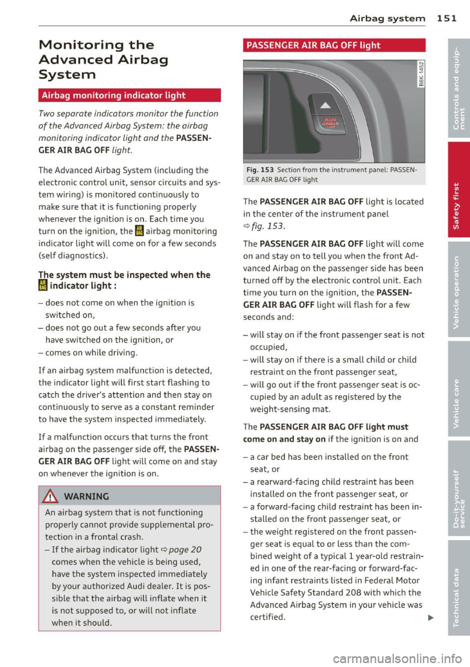
The PAS SENG ER AIR BAG OFF light is located
in the center of the instrument pa ne l
¢ fig. 153 .
The PAS SENG ER AIR BA G OFF light will come
on and stay on to tell you when the front Ad
vanced Airbag on the passenger s ide has been
tu rned off by the electronic cont rol unit. Each
time you turn on the ignition, the
PASSEN
GE R AIR BA G OFF
light will flash for a few
seconds and:
- wi ll stay on if the front passenger seat is not
occupied,
-w il l stay on if there is a small ch ild or child
restraint on the front passenger seat,
- w ill go out if the front passenger seat is oc
cupied by an adult as registered by the
weight-sensing mat .
The
PAS SEN GER AIR BAG OFF li ght mu st
co m e on and st ay o n if the ignition is on and
- a car bed has been installed on the front
seat, or
- a rearward -facing child restraint has been
installed o n the front passenger seat, or
- a forward-fac ing child restraint has been in
stalled on the front passenger seat , or
- the weight registered on the front passen
ger seat is equal to or less than the com
bined weight of a typical 1 year-old restra in
ed in one of the rear-facing or forward-fac
ing infan t restra ints listed in Federal Motor
Veh icle Safety Standard 208 wi th which the
Advanced A irbag System in your vehicle was
certified.
111-
Page 157 of 290
dealer is familiar with these requirements
and we recommend that you have your
dealer perform this service for you.
Other things that can affect Advanced
Airbag performance
Changing the vehicle's suspension system can
change the way that the Advanced Airbag Sys
tem performs in a crash. For example, using
tire-r im combinations not approved by Audi,
lowering the vehicle, changing the stiffness of
the suspension, including the springs, suspen
sion struts, shock absorbers etc. can change
the forces that are measured by the airbag sensors and sent to the electronic control
unit. Some suspension changes can, for exam
ple, increase the force levels measured by the
sensors and make the airbag system deploy in
crashes in which it would not deploy if the
changes had not been made . Other kinds of
changes may reduce the force levels meas
ured by the sensors and prevent the airbag
from deploying when it should .
The sensors in the safety belt buckle for the
d river and front passenger seat tell the elec
tronic control module if the safety belt is
latched or not. If the safety belt is being used,
the front airbag will deploy at a slightly high
er rate of vehicle deceleration than if the safe
ty belt is not being used. Therefore, in a par
ticular collision, it is possible that an airbag
will not deploy at a seating position where the safety belt is being used but will inflate at the
position where the safety belt is not being
used. It is important that nothing interfere
with the safety belt buckles so that the sen
sors can send the correct information about
safety belt use to the electronic control unit.
.&_ WARNING
Changing the vehicle 's suspension includ
ing use of unapproved tire-rim combina
tions can change Advanced Airbag per
formance and increase the risk of serious personal injury in a crash.
- Never install suspension components
that do not have the same performance
Airbag system 155
characteristics as the components origi
nally installed on your vehicle .
- Never use tire-rim combinations that
have not been approved by Audi.
.&_ WARNING
= -
Items stored between the safety belt buckle and the center console can cause
the sensors in the buckle to send the
wrong information to the electronic con
trol module and prevent the Advanced Air bag System from working properly.
-Always make sure that nothing can inter-
fere with the safety belt buckles and that
they are not obstructed.
Knee airbags
Description of knee airbags
Applies to vehicles: wit h knee airbags
The knee airbag system can provide supple
mental protection to properly restrained
front seat occupants.
Fig. 154 Driver 's knee airbag
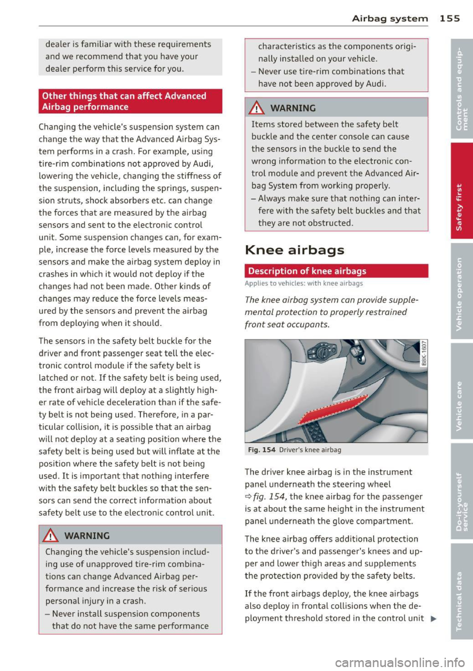
The driver knee airbag is in the instrument
panel underneath the steering wheel
Q fig . 154, the knee airbag for the passenger
is at about the same height in the instrument
panel underneath the glove compartment .
The knee airbag offers additional protection
to the driver's and passenger's knees and up
per and lower thigh areas and supplements
the protection provided by the safety belts.
If the front airbags deploy, the knee airbags
also deploy in frontal collisions when the de ployment threshold stored in the control unit
I),-