rear view mirror AUDI A5 CABRIOLET 2015 Owners Manual
[x] Cancel search | Manufacturer: AUDI, Model Year: 2015, Model line: A5 CABRIOLET, Model: AUDI A5 CABRIOLET 2015Pages: 268, PDF Size: 66.88 MB
Page 56 of 268
Lights and Vision
Q/P -Adjusting the left/right exterior mirror .
Move the knob in the des ired direction.
4ill -Heat ing the m irror g lass depending on the
outside temperature*.
.9 -Folding exterior mirrors* . In the Infotain
ment system, you can select if the mirrors fold in
automatically when you lock the vehicle
¢ page 34.
Front passenger's exterior mirror tilt
function*
To help you see the curb when backing into a
parking space, the surface of the mirror t ilts
slightly . Fo r this to happen, the knob must be in
the position for the front passenger 's outside
mirror.
You can adjust the tilted mirror su rface by turn
ing the knob in the des ired direction . When you
move out of reverse and into another gear, the
new mirror position is stored and assigned to the
key you are using.
The mirror goes back into its origina l position
once you drive forward faster than 9 mph (15 km/h) or turn the ignition off.
A WARNING
Curved mirror surfaces (convex or spherical*)
increase your field of view. Remember that
vehicles or other objects will appear smaller
and farther away than when seen in a flat mir
ror. If you use this mirror to estimate distan
ces of following vehicles when changing
lanes, you cou ld estimate incorrectly and
cause an accident.
(D Note
-If the mirror hous ing was moved by force
(for example, by running into an object
when maneuvering the vehi cle), the mirror
must be folded all the way in using the pow
er folding function. The mirror housing
must not be moved back into place by hand
because this would impair the function of
the mirror mechanism.
- If you wash the vehicle in an automatic car
wash, you must fold the exterior mirrors in
54 to reduce
the risk of damage to the mirrors.
Never fold power folding exterior mirrors*
by hand. Only fold them in and out using
the power controls.
(D Tips
-If the power adjusting function malfunc
tions, the g lass in both mirrors can be ad
justed by pressing on the edge of it by hand.
- The exterior mirror settings are stored with
the memory function* ¢
page 63.
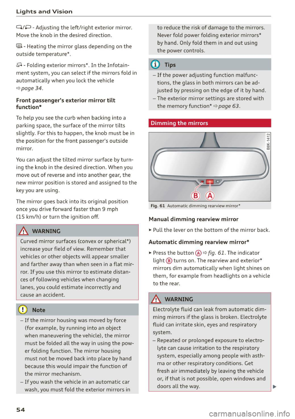
Dimming the mirrors
Fig. 61 Auto mat ic dimmin g rearv iew mirro r•
Manual dimming rearview mirror
.,. Pull the lever on the bottom of the m irror back .
Automat ic dimming rearview mirror*
.,. Press the button@¢ fig. 61. The indicator
light @ turns on . The rearview and exter ior*
mirrors dim automatically when light shines on
them, for example from headlights on a vehicle
to the rear.
~ WARNING
Electro lyte fluid can leak from automatic dim
ming mirrors if the glass is broken. Electrolyte
fluid can irritate skin, eyes and respiratory system.
- Repeated or prolonged exposure to e lectro
lyte can cause irritation to the respiratory
system, especially among people with asth
ma or other resp iratory conditions . Get
fresh a ir immediately by leaving the vehicle
or, if that is not possible, open windows and
doors all the way.
~
Page 57 of 268
M N
ci LL co
rl I.O
"' N
"' rl
-If electrolyte gets into the eyes, flush them
thoroughly with large amounts of clean wa
ter for at least 15 minutes; medical atten
tion is recommended .
- If electrolyte contacts skin, flush affected
area with clean water for at least 15 mi nutes and then wash affected area with
soap and water; medical attention is recom
mended. Thoroughly wash affected clothing
and shoes before reuse.
-If swallowed and person is conscious, r inse
mouth with water for at least 15 minutes.
Do not induce vomit ing unless instructed to
do so by medical professional. Get medical
attention immediate ly .
(D Note
Liquid electrolyte leaking from broken mirror
glass will damage any plastic surfaces it
comes in contact with. Clean up spilled elec
trolyte immediate ly with clean water and a
sponge .
@ Tips
-Switch ing off the dimming function of the
i nside rear view mirror also deactivates the
automatic dimming function of the exterior
mirrors .
- Automatic dimming for the mirror only op
erates properly if the light striking the in
side mirror is not h indered by other objects.
- The automatic dimming mirrors do not dim
when the interior lighting is turned on or
the reverse gear is selected.
Sun visors
T.__~l
Fig. 62 Dr ive r"s side: su n visor
Lights and Vision
The sun visors for the driver and passenger can
be pulled out of their brackets in the center of
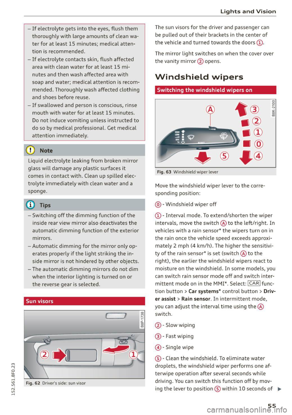
the vehicle and turned towards the doors@.
The mirror light switches on when the cover over
the vanity mirror @opens .
Windshield wipers
Switching the windshield wipers on
®
Fig. 63 Winds hield w iper leve r
Move the windshield wiper lever to the corre
sponding position:
@ -Windshield wiper off
(D-Interval mode . To extend/shorten the wiper
intervals, move the switch @to the left/right. In
vehicles with a ra in sensor* the wipers turn on in
the rain once the vehicle speed exceeds approxi mately 2 mph (4 km/h). The higher the sensitivi
ty of the rain sensor* is set (switch @to the
right), the earlier the windshield wipers react to
moisture on the windshield . In some models, you
can switch ra in sensor mode off and switch inter
mittent mode on in the MMI* . Select :
ICARI func
t ion button
> Car systems* control button > Driv
er assist> Rain sensor .
In intermittent mode,
you can adjust the interval time using the@
switch.
@ -Slow w iping
@ -Fast wip ing
@ -Single wipe
® -Clean the w indshield. To elim inate water
droplets, the windsh ield wiper performs one af
terwipe operation after several seconds while driving. You can switch this function off by mov -
ing the lever to posit ion ® within 10 seconds of ..,.
55
Page 59 of 268
M N
ci LL co
rl I.O
"' N
"' rl
.. Select: ICARI function button> Car systems*
control button > Servicing & checks > Wiper
service position
> On/Off .
Removing the wiper blade
.. Lift the windshie ld wiper arm up from the wind
shield.
.. Press the locking knob
@¢fig . 64 on the wiper
blade. Hold the wiper b lade firm ly.
.. Remove the wiper blade in the direction of the
arrow .
Attaching the wiper blade
.. Install the new wiper blade in the retainer on
the wiper arm@ unti l you hear it click into
place on the wiper arm .
.. Place the wiper arm back on the windshie ld.
.. Turn the service pos ition off.
A WARNING
For your safety, you should replace the wiper
blades once or twice a year. See your author
ized Aud i dea ler for replacement blades.
(D Note
-The windshield wiper blades must only be
replaced when in the service position! Oth
erwise, you r isk damaging the paint on the
hood or the windshield wiper motor.
- You should not move your vehicle or press
the windshie ld w iper lever when the wiper
arms are folded away from the windshield .
The windshield wipers would move back in
to their original position and could damage
the hood and windshield.
- To he lp prevent damage to the wiper sys
tem, always loosen blades which are frozen
to the windshie ld before operating wipers .
- To he lp prevent damage to w iper blades, do
not use gasoline, kerosene, paint thinner, or
other solvents on or near the wiper blades.
- To he lp prevent damage to the wiper arms
or other components, do not attempt to
move the wipers by hand .
Lights and Vision
(D Tips
-Commercial hot waxes applied by automatic
car washes affect the how easily the glass
surface can be cleaned.
- You can also use the service position, for ex
ample, if you want to protect the windshield
from icing by using a cover .
Digital compass
Switching the compass on and off
Appl ies to veh icles : w ith dig it a l co mp ass
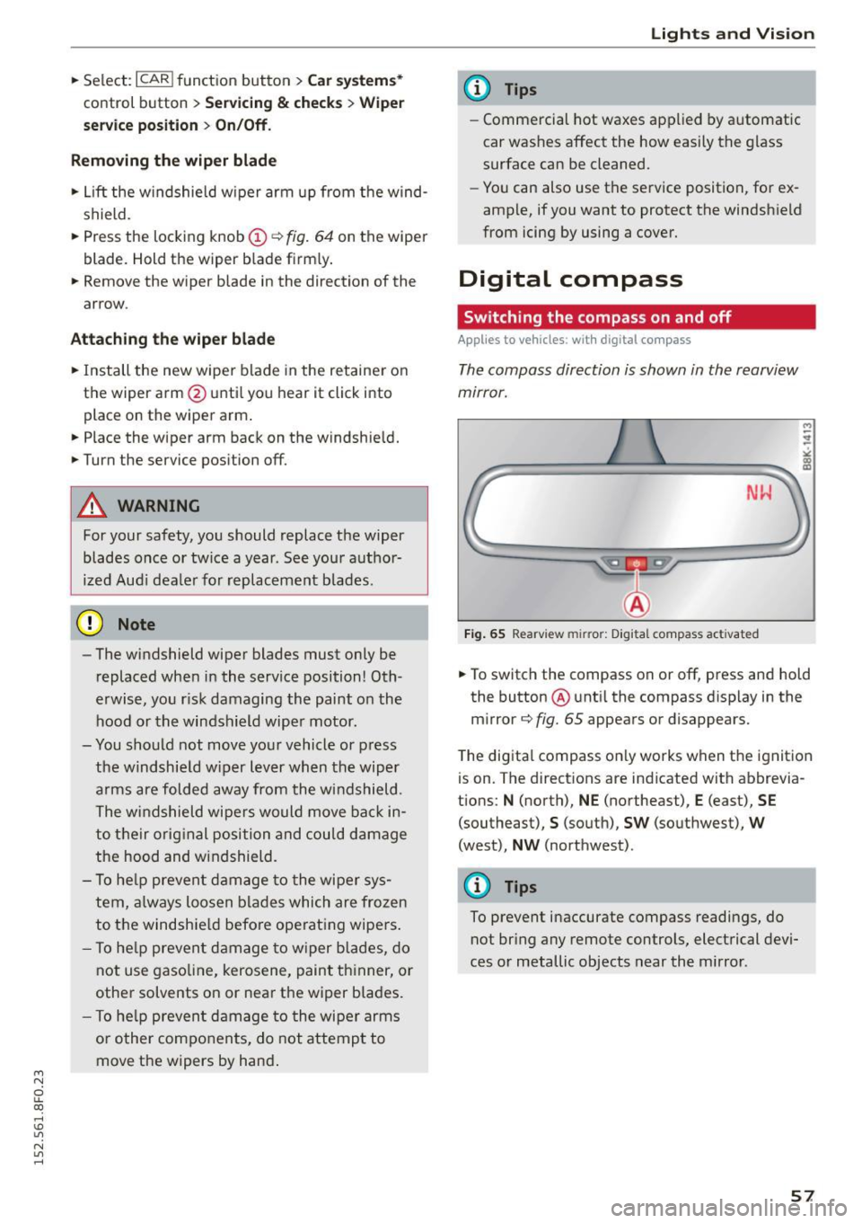
The compass direction is shown in the rearview
mirror.
Fig. 65 Rearv iew mirr or: Digita l compass act ivated
M
-
.. To switch the compass on or off, press and hold
the button @ unti l the compass d isplay in the
mirror¢
fig. 65 appears or disappears.
The digita l compass only works when the ignition
is on. The directions are indicated with abbrevia
tions: N (north), NE (northeast), E (east), SE
(southeast),
S (south), SW (southwest), W
(west), NW (northwest) .
@ Tips
To prevent inaccurate compass readings, do
not bring any remote controls, electrical devi
ces or metallic objects near the mirror .
57
Page 60 of 268
Lights and Vi sion
Adjusting the magnetic zone
Applies to vehicles: with digital compass
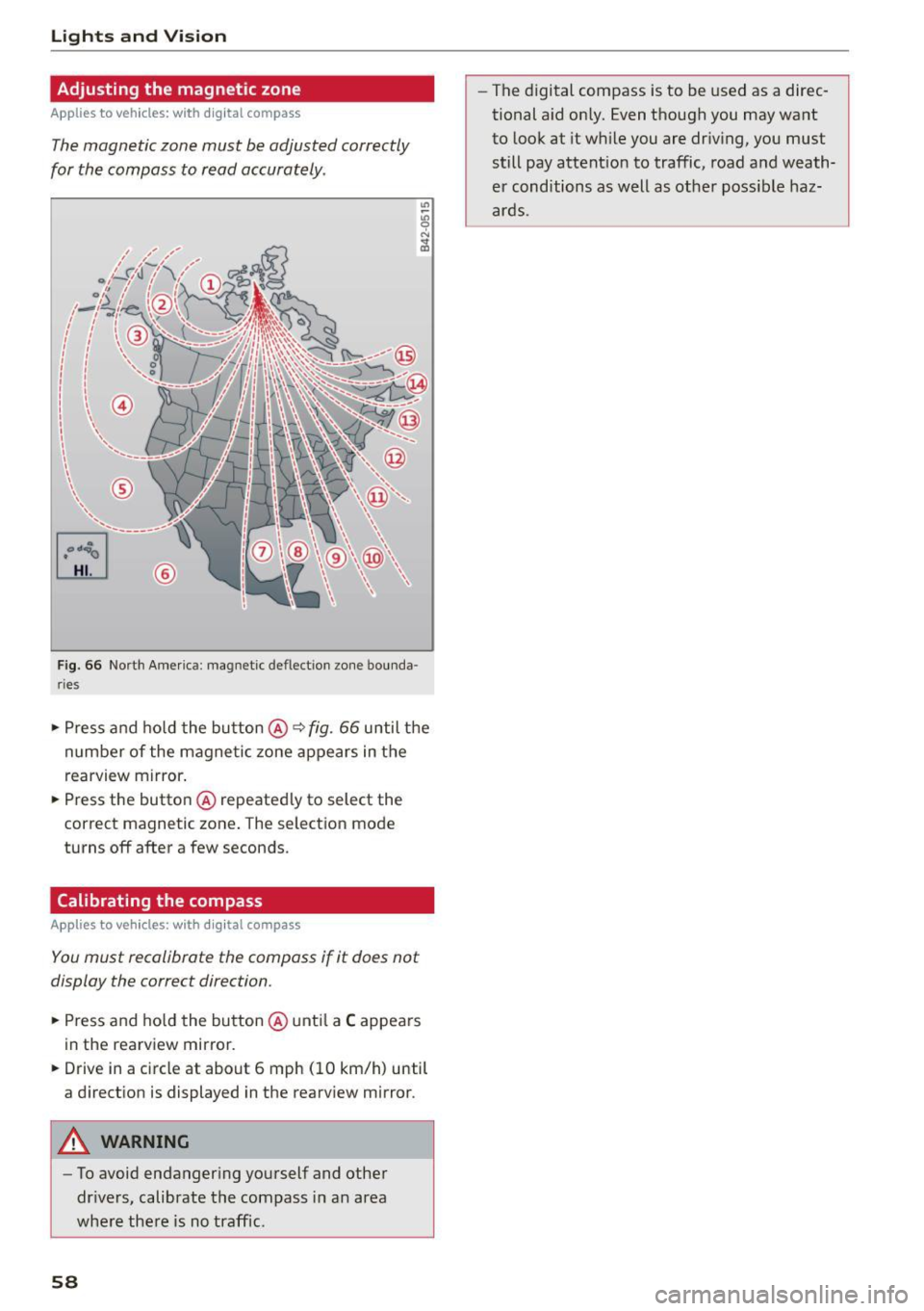
The magnetic zone must be adjusted correctly
for the compass to read accurately .
~
LIU ®
Fig . 6 6 No rth A meri ca: magnet ic deflection zo ne bo unda
ri es
"' Press a nd ho ld the button @~ fig. 66 until the
number of the magne tic zone ap pears in the
rearview mirror .
"' Press the butto n @ repeated ly to select the
correct magnetic zone . The selection mode
turns off after a few seconds.
Calibrating the compass
Applies to vehicles: w ith d ig ital compass
You must recalibrate the compass if it does not
display the correct direction.
"'Press and ho ld the bu tton @unt il a C appea rs
in the rearview mirror.
"' Drive in a circle at about 6 mph (10 km/h) until
a direct ion is displayed in the rearv iew m irror .
A WARNING
-To avoid endanger ing yo urself and othe r
dr ivers, calibrate the compass i n an area
whe re the re is no traffic.
58
- The digital compass is to be used as a direc
tional a id on ly. Even though you may want
to look at it wh ile you are dr iv ing, you must
still pay attent io n to traffic, road a nd weath
er cond itions as well as other poss ible haz
ar ds.
Page 101 of 268

M N
ci LL co
rl I.O
"' N
"' rl
Audi side assist Side assist
Description
Applies to vehicles: with Audi side assist
Fig. 114 Se nsor detection range
Fig. 1 15 Display o n the exterio r m irro r
Side assist helps you monitor your blind spot and
traffic behind your veh icle . With in the limits of
the system, it wa rns you about vehicles that are
coming closer or that are traveling w ith you with
i n sensor range
(D c::, fig. 114 : if a lane change is
classified as crit ical , the disp lay @ in the exter io r
mirror ¢
fig. 115 turns on.
The display i n the left exterior mirror provides as
sistance when making a lane cha nge to the left,
while the d isp lay in the right exterio r mir ror pro
vides assistance whe n mak ing a lane change to
the r ight .
Information stag e
As long as you do not activate the turn signal,
side assist
informs you about ve hicl es that a re
detected and class ified as crit ica l. The display in
the respective mirror tu rns on, but is dim.
Aud i side assist
The display remains d im intentionally in the in
formation stage so that your view toward the
front is not d isturbed .
Warning sta ge
If you activ ate the turn s ignal, s ide ass ist warns
you about vehicles that are detected a nd classi
fied as critica l. The d isplay in the respective mir
ror blinks brightly . If this happens, check traffic
by g lancing in the rearview mirror and over your
shoulder
c::, .&. in General information on
page 100.
{!) Tips
- Yo u can adjust the brightness of the display
@ c:;, page 101.
-Please refer to the instructions for towing a
trailer located in
c::, page 100 .
99
Page 103 of 268

M N
ci LL co
rl I.O
"' N
"' rl
-Improper reliance on the side assist system
can cause collisions and serious personal in
jury:
- Never rely only on side assist when chang
ing lanes .
- Always check rear view mirrors to make
sure that it is safe to change lanes.
- Sid e assist cannot detect a ll vehicles under
all conditions- danger of accident!
- Please note that side assist indicates there
are approaching vehicles, or vehicles in your
blind spot, only after your vehicle has
reached a driving speed of at least 19 mph
(30 km/h).
- In certain situations, the system may not
function or its function may be limited. For
example:
- if vehicles are approaching or being left
behind very quickly. The display may not
turn on in time.
- in poor weather conditions such as heavy
rain, snow or heavy m ist .
- on very wide lanes, in tight curves or if
there is a rise in the road surface . Vehicles
in the adjacent lane may not be detected
because they are outside of the sensor
range.
(D Note
The sensors can be displaced by impacts or
damage to the bumper, wheel housing and
underbody. This can affect the system . Have
your authorized Audi dealer or authorized
Audi Service Facility check their function.
(D Tips
-If the window g lass in the driver's door or
front passenger's door has been tinted, the
display in the exterior mirror may be misin
terpreted.
- For Declarat ion of Compliance to United
States FCC and Industry Canada regulations
~page 251.
Audi side assist
Activating and deactivating
Applies to vehicles: wit h Audi side ass ist
Fig. 118 Driver 's doo r: Sid e assist button
" Press the button ¢ A in General information
on page 100
to switch the system on/off . The
LED in the button turns on when side assist is
switched on .
Adjusting the display brightness
Applies to vehicles: wit h Audi side ass ist
The signal brightness can be set in the radio or
MM!*.
.,. Select: !CARI function button> Audi side assist.
.,. Select: !CARI function button> Car systems*
control button > Driver assist> Audi side as
sist .
The display brightness adjusts automatically to
the brightness of the surroundings, both in the
information and in the warning stage . In very
dark or very bright surround ings, the display is al
ready set to the minimum or maximum level by
the automatic adjustment . In such cases, you
may notice no change when adjusting the bright
ness, or the change may only be noticeable once
the surroundings change.
Adjust the br ightness to a level where the display
in the information stage will not disrupt your
view forward. If you change the brightness, the
display in the exterior mirror will briefly show the
brightness level in the information stage. The
brightness of the warning stage is linked to the
brightness in the information stage and is adjust
ed along with the information stage adjustment . ..,_
101
Page 112 of 268

Parking System
-You can change the volume and pitch of the
signals as well as the display
~ page 112.
-What appears in the display is time-delayed.
Reverse Parking
App lies to veh icles: w ith pa rking system (rea r, w ith rea r v iew
camera)
Parking mode 1 can be used when parking in a
garage or parking space.
Fig. 125 MM I Di splay: Aiming at a parking spot
Fig . 126 MMI Di splay: Al ignin g th e ve hicle
• Switch the MMI on and select the reverse gear.
• Turn the steering wheel until the orange orien
tation lines
(D appear in the parking spot
¢ fig. 125. Use the markings @to help you es
timate the distance from an obstacle. Each
marking corresponds to 3
ft (1 m). The blue
area represents an extension of the vehicle's
outline by approximately
16 ft (5 m) to the
rear .
• While driving in reverse gear, adjust the steer
ing wheel angle to fit the parking space with
the aid of the orange orientation lines ¢0 .@
marks the rear bumper. You should stop driving
in reverse as soon as and no later than when
the red orientation line @abuts an object
¢ _& !
110
A WARNING
- The rear view camera does not show the en
tire area behind the vehicle¢
page 108,
fig . 123.
Watch out especially for small chil
dren and animals . The rear view camera can
not always detect them, posing risk of an
accident!
- Please note that objects not touching the
ground can appear to be further away than
they really are (for example, the bumper of
a parked vehicle, a trailer hitch, or the rear
of a truck). In this case, you should not use
the help lines to help with parking, which poses danger of an accident!
cg) Note
- Low obstacles already signaled by a warning can disappear from the system's detection
range as they are approached and will not
continue to be signaled. Objects such as
barrier chains, trailer draw bars, thin paint
ed vertical poles or fences may not be de
tected by the system, posing risk of dam age.
- In the MMI display, the direction of travel of the vehicle rear is represented depending on
the steering wheel angle. The vehicle front
swings out more than the vehicle rear. Main
tain plenty of distance from an obstacle so
that your outside mirror or a corner of your
vehicle does not collide with any obstacles -
danger of accident!
Page 114 of 268

Parkin g Sys tem
sw ings out more than the vehicle rear . Main
tain plenty of distance from an obstacle so
that your outside mirror or a corner of your
veh icle does not collide w ith any obstacles -
danger of accident!
(D Tips
The left or right orientation lines and surfaces
w ill be displayed, depending on the turn sig
nal being used.
Adjusting the display and warning tones
Applies to vehicles: w ith parking system (rear, with rear view
camera)
The display and warning tones ore adjusted in
the radio or MMI*.
.. Se lect: ICARlfunct ion button> Parking sy stem .
Or
.. Se lect: ICAR I function button> Car system s*
control button > D riv er a ss is t> Par king aid .
D isplay
- Off -when the pa rking system is switched on,
o nl y aud ible signals are given.
- On -when the pa rking system is switched on,
the p icture from the rear view camera is dis
played.
Warning tones
- Rea r volume -
rear sensor volume
-Rear frequenc y -rear sensor frequency
- Music volume wh ile pa rking -when the pa rk-
ing system is switched on, the volume of the
active aud io source is lowered .
The newly adjusted value is briefly heard from
the signal generator. The settings are automati
cally stored and assigned to the remote control key .
A WARNING
- Always make sure that the volume and fre
quency of the wa rning tones is adj usted so
that you can eas ily hear the acoust ic dis
tan ce signal even if the radio is p laying, the
air-con ditione r blower is on High or t here is
a high level of outside noise .
112
-Check the settings whenever someone else
has dr iven the vehicle before you .
@ Tips
-The warn ing tones can also be adjusted di
rectly from the rear view camera image.
Simply press the Settings * cont ro l button .
- Changed settings are activated when park
ing assist is switched on again.
Error messages
Applies to vehicles: with parking system (rear, with rear view
camera)
If a warning tone is aud ible for about five sec
onds when you turn on the ignition, there is a malfunction in the system. Have the problem cor
rected by your author ized Audi dealer .
Keep the sensors in the rea r bumper clean and
free from ice so that the aco ustic park assist sys
tem can function properly .
Page 239 of 268

M N
ci LL co
rl I.O
"' N
"' rl
Fu se pa nel @ (black )
No. Consumer
1 Dynamic steering
2 Electron ic Stabilization Control (module)
A/C system pressure sensor, electrome-
chanical parking brake, HomeLink, auto-
3 mat
ic dimming interior rear view mirror,
air quality/outside air sensor, Electron ic
Stabilization Control (button)
s Sound actuator
6 Headlight range control/headl
ight (corner-
ing light)
7 Headlight (cornering light)
Control modu les (electromechanical park-
8 ing brake, shock absorber, q uattro sport),
DCDC converte r
9 Adaptive
cruise control
10 Shift gate/clutch sensor
11 Side assist
1 2 Headlight range cont ro l, parking system
13 Airbag
14 Rear
wiper (a llroad)
15 Auxiliary fuse (instrument panel)
16 Auxiliary
fuse termina l 15 (engine area)
Fuse p anel @ (brown )
No. C onsumer
2 Brake light sensor
3 Fuel pump
4 Clutch sensor
5
Left seat heating with/without seat venti-
lation
6 Electronic Stabilization Control (electric)
7 Ho rn
8
Front left door (window regulator, central
locking, mirror, switch, lighting)
9 Windshield wiper motor
10 Electronic Stabilization Control (valves) Fu
ses a nd bulb s
No. Consumer
Two-door mode ls: rear left window regula-
11 tor; Four-door
models: rear left door (win-
dow regulator, central locking, switch,
light ing)
12 Rain and l
ight sensor
Fuse panel © (r e d )
No . Con sumer
3 Lumbar support
4 Dynamic steering
5 Inter
ior l ight ing (Cabriolet)
6 Windshie
ld washer system, headlight
washer system
7 Vehicle electrica l system control module 1
8 Vehicle electr ica l system control module 1
9 Left rear
window regulator motor (Ca brio-
let)/su nroof
10 Vehicle electr ica l system co ntrol module 1
11 Right rear
window regulator (Cabriolet)/
sun shade motor
12 Anti-theft
alarm warning system
Right cockpit fuse assignment
Fig. 195 Right cockpit: fu se panel with plastic cl ip
237
Page 241 of 268
M N
ci u.. co ,...., \!) 1.1'1
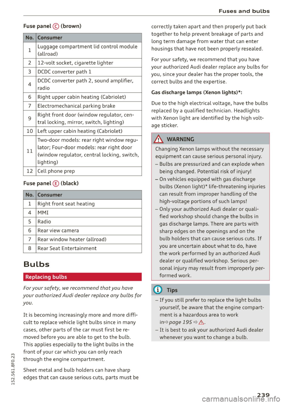
N 1.1'1 ,....,
Fuse panel© (brown)
No. Consumer
1 Luggage compartment lid control module
(allroad)
2 12-volt socket, cigarette lighter
3 DCDC converter path 1
4 DCDC converter path 2, sound amplifie r,
rad io
6 Right upper cabin heating (Cabriolet)
7 Electromechanical parking brake
9
Right front door (window regulator, cen-
tral locking, mirror, switch, lighting)
10 Left upper cabin
heating (Cabriolet)
Two-door models: rear right w indow regu-
11 lator; Four-door models: rear
right door
(window regulator, central locking, switch,
lighting)
12 Cell phone prep
Fuse
panel © (black)
No. Consumer
1 Right front seat heating
4 MMI
5 Radio
6 Rear view camera
7 Rear window heater (allroad)
8 Rear
Seat Entertainment
Bulbs
Replacing bulbs
For your safety, we recommend that you have
your authorized Audi dealer replace any bulbs for
you .
It is becoming increasingly more and more diffi
cult to replace vehicle light bulbs since in many
cases , other parts of the car must first be re
moved before you are ab le to get to the bulb .
This applies especially to the light bulbs in the
front of you r ca r which you can only reach
through the engine compartment .
Sheet metal and bulb holders can have sharp
edges that can cause ser ious cuts, parts must be
Fuses and bulbs
correct ly taken apart and then properly put back
together to help prevent breakage of parts and
long term damage from water that can enter
housings that have not been properly resealed.
For your safety, we recommend that you have
your authorized Audi dea ler replace any bulbs for
you, since your dealer has the proper tools, the
correct bulbs and the expertise.
Gas discharge lamp s (Xenon lights)*:
Due to the high electr ical voltage, have the bulbs
replaced by a qualified technician . Head lights
with Xenon light are identified by the high volt
age sticker.
A WARNING
Changing Xenon lamps without the necessary
equipment can cause serious personal injury.
- Bulbs are pressurized and can explode when
being changed . Potential risk of injury!
- On vehicles equipped with gas discharge
bu lbs (Xenon light) * life -threatening injuries
can result from improper handling of the
high -vo ltage portions of such lamps!
-On ly your authorized Audi dealer or quali
fied workshop shou ld change the bulbs in
gas discharge lamps. There are parts with
sharp edges on the openings and on the
bulb holders that can cause serious cuts . If
you are uncertain about what to do, have
the wor k performed by an autho rized Audi
dealer or qualified workshop. Serious per
sonal injury may result from improperly per
formed work .
(D Tips
-If you st ill prefer to replace the light bulbs
yourself, be aware that the eng ine compart
ment is a hazardous area to work
inq page 195 q &..
-It is best to ask your authorized Audi dealer
whenever you want to change a bulb.
239