manual radio set AUDI A5 CABRIOLET 2017 Owners Manual
[x] Cancel search | Manufacturer: AUDI, Model Year: 2017, Model line: A5 CABRIOLET, Model: AUDI A5 CABRIOLET 2017Pages: 266, PDF Size: 66.64 MB
Page 9 of 266

a:,
a:,
...... N r--. N ...... 0
0
LL 00
CD
@
®
©
®
®
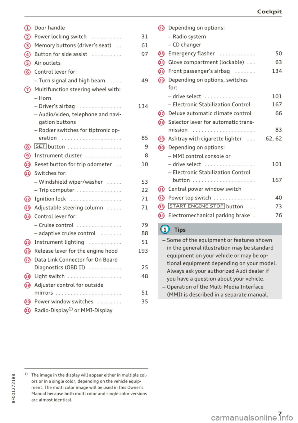
Door handle
Power locking switch
Memory buttons (driver's seat) . .
Button for side assist
A ir outlets
Contro l lever for:
- Turn signal and high beam
0 Multifunction steering wheel with:
- Horn
- Driver's airbag ........... .. .
- Audio/v ideo, telephone and nav i-
gation buttons
- Rocker switches for tiptron ic op -
eration .. ............. .. .. .
@ ISETI button ................ . .
® Instrument cluster ........... .
@
@ Reset button for trip odometer
Switches for:
- Windsh ield wiper/washer
- Trip computer .............. .
I gnition lock ................ .
Adjustable steering column
Contro l lever for:
- Cruise control .............. .
- adaptive cruise control ..... . .
@ Instrument lighting ........ .. .
@ Release lever for the engine hood
@ Data Link Connector for On Board
Diagnostics (OBD II) ........ .. .
@ Light switch ..... ....... ..... .
@ Adjuste r contro l for outside
mirrors . ... ................ . .
@ Power window switches . .. .... .
@ Radio-Display1l or MMI -Display
31
61
97
49
134
85
9
8
10
53
22
71
71
79
88
51
193
25
48
51
35
ll The image in t he d is pl ay wil l appear either in m ultiple col
o rs or in a single colo r, depending on the vehicle e quip
ment. The multi co lor im age will be used in this Owne r's
Man ual bec ause both multi co lor and single co lo r ve rsio ns
ar e almo st identica l.
@ Depending on options:
- Radio system
- CD changer
Emergency flasher
G love compartment ( lockable) .. .
Front passenger's airbag ...... .
Depend ing on options, switches
for:
- drive select .. .............. .
- Electronic Stabilization Control .
@ Deluxe automatic climate control
@ Selector lever for automatic trans-
mission . ... .. .. ............ .
@ Ashtray with cigarette lighter
@ Depending on options:
- MMI control console or
- drive select . ... ............ .
- Elect ronic Stabilization Control
button .. .. .. .. ............ .
@ Centra l power window switch
@ Power top switch . ............ .
@ I S TAR T ENGINE S TOP I button .. .
@ Electromechanical parking brake
0) Tips
Cockpit
so
63
134
101
167
66
83
62,62
101
167
40
73
76
- Some of the equipment or features shown in the general illustration may be standard
equipment on your veh icle or may be op
tional equ ipment depending on your model.
Always ask your authorized Audi dealer if
you have a question about your vehicle.
- Operation of the Multi Media Interface
(MMI) is described in a separate manual.
7
Page 12 of 266

Instrumen ts and ind icator ligh ts
the I SET! button, you de lete the warning thresh
old.
Digital clock with date display and
Odometer
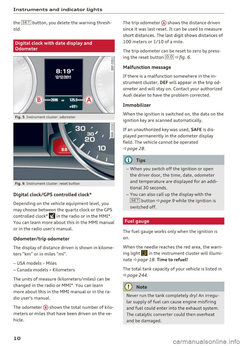
F ig . 5 Ins trum en t cluster: odo meter
Fig . 6 Instrument cluster: reset bu tton
Digi tal clock/GP S controll ed cl ock*
Depending on the vehicle equipment level, you
may choose between the quartz clock or the
GPS
controlled clock* l!j in the radio or in the MMI *.
You can learn more about this in the MMI manual
or in the rad io user 's manual.
Odometer /t ri p odomete r
The display of distance driven is shown in kilome
ters "km" or in miles "mi".
- USA mode ls - Miles
- Canada models - Kilometers
The units of measure (kilometers/miles) can be changed in the radio or MMI* . You can learn
mo re about this in the MMI manual or in the ra
d io user's manual.
The odometer @ shows the total number of kilo
meters or miles that have been driven on the ve
h icle .
10
The trip odometer @ shows the distance driven
since it was last reset.
It can be used to measure
short distances. The last digit shows distances of
100 meters or 1/10 of a mile .
The trip odometer can be reset to zero by press
ing the reset button
!O.O I ¢ fig. 6.
Malfunction message
If there is a malfunction somewhe re in the in
strume nt cluster,
DEF w ill appear in the tr ipod
ometer and w ill stay on. Contact yo ur authorized
Aud i dealer to have the prob lem corrected.
Immobilizer
When the ignition is switched on, the data on the
i gnition key are scan ned automat ica lly .
If an unauthor ized key was used,
SAFE is d is·
played permanently in the odomete r display
field . The vehicle cannot be operated
¢ page 28.
{i) Tips
- When you switch off the ignition or open
the driver door, the time, date, odometer
and tempe rature are displayed for an addi
tional
30 seconds.
- You can also call up the display with the
!SE T! button¢ page 9 w hile the ign ition is
switched off .
Fuel gauge
The fuel gauge works only when the ignition is
on.
When the needle re aches the red area, the warn
i ng l ight
li'J in the instrument cluster wi ll illumi
nate ¢
page 18. Time to refuel!
The tota l tank capacity of your ve hicle is listed in
¢ page 244.
(D Note
Neve r run the tan k comp letely dry! An ir regu
l a r supply of fuel can cause eng ine misfiring
and fuel could enter in to the exhaust system .
The cata lytic conver ter cou ld the n overheat
and be damaged.
Page 25 of 266

a:,
a:,
.... N r--. N .... 0
0
LL 00
(memory level 2). The fuel pump nozzle iii
indicates the efficiency program*¢ page 24.
Single-trip memory (Trip computer 1)
The single-trip memo ry stores the trip informa
tion from the tim e the igni tion is turned on until
it is turned
off. If the tr ip is continued within 2
hours from the time the ignition was turned off,
the new data will be included in the calculation of
the current trip information.
If the trip is inter
rupted for
more than 2 hours the memory is re
set automat ically.
Total -trip memory (Trip computer 2)
Unlike the single-trip memory, the tota l-trip
memory is not reset automatically. This permits
you to evaluate your driving data for the entire
period between manual resets.
Efficiency program*
The efficiency program can help you to use less
fuel¢
page 24.
Operation
The trip computer is controlled by two switches
on the windshield wiper lever.
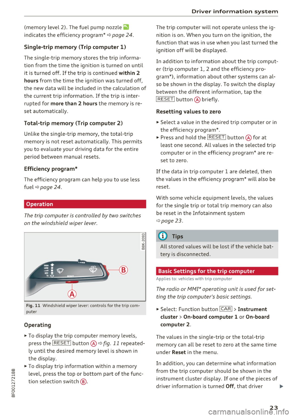
Fig. 11 Wind shield w iper leve r: controls fo r th e tr ip com
p u ter
Operating
"'To display the trip computer memory levels,
press the
I RESE T! button @¢ fig. 11 repeated
ly until the desired memory level is shown in
the display.
"' To display trip information within a memory
level, press the top or bottom part of the func
t ion selection switch @.
Driver information system
The trip computer will not operate unless the ig
nition is on. When you turn on the ignition, the
function that was in use when you last turned the
ignition off will be disp layed.
In addition to information about the trip comput
er (trip computer 1, 2 and the efficiency pro
gram*), information about other systems can al
so be shown in the display. To sw itch the display
between the different information, tap the
I RESET ! button@ briefly .
Resetting values to zero
.,. Select a value in the desired trip computer or in
the efficiency program* .
"' Press and hold the
I RESET ! button@ for at
least one second . All values in the selected trip
computer or in the efficiency program* are re
set to zero .
If the data in tr ip computer 1 are deleted, then
the values in the efficiency program* will also be
reset .
With some vehicle eq uipment levels, the values
for the single trip or total trip memory can also
be reset in the Infotainment system
¢page 23.
(D Tips
All stored values will be lost if the vehicle bat
tery is disconnected .
Basic Settings for the trip computer
Applies to: vehicles with trip computer
The radio or MM!* operating unit is used for set
ting the trip computer 's basic settings.
.,. Select: Function button !CAR !> Instrument
cluster
> On-board computer 1 or On-board
computer
2 .
The values in the sing le-trip or the total-trip
memory can all be reset to zero at the same time
under
Reset i n the menu.
In addition, you can determine what information
from the trip computer should be shown in the
instrument cluster display . If one of the pieces of
driver information is turned
Off , that dr iver 1111>
23