start stop button AUDI A5 COUPE 2015 Owners Manual
[x] Cancel search | Manufacturer: AUDI, Model Year: 2015, Model line: A5 COUPE, Model: AUDI A5 COUPE 2015Pages: 264, PDF Size: 66.83 MB
Page 11 of 264
M N
i? co ,...., \!) ..,.,
N l/'I ,....,
CD
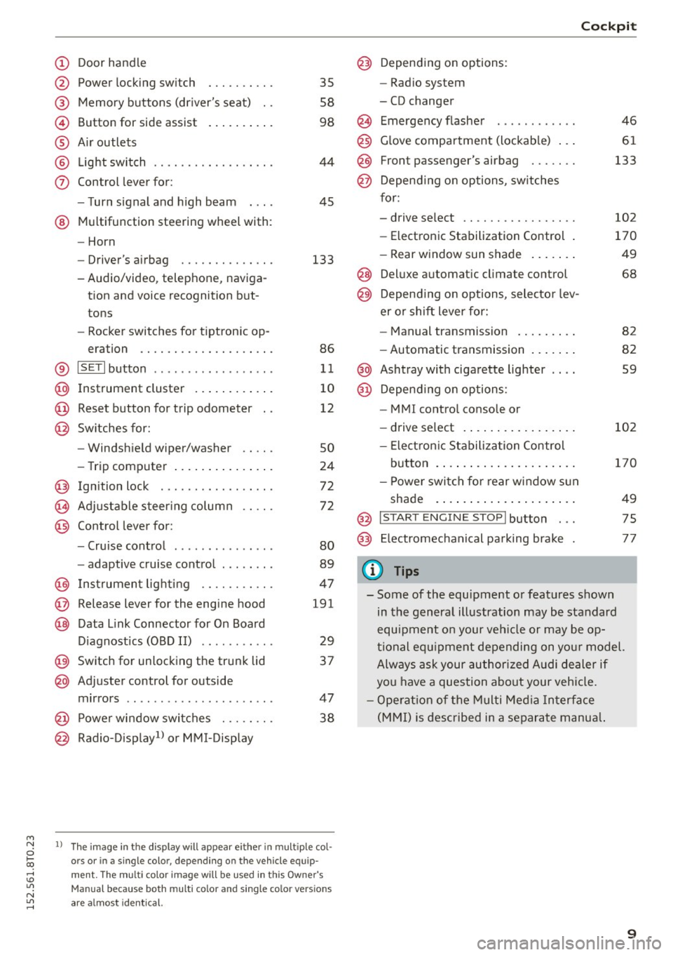
@
®
©
®
®
(j)
Door handle
Power locking swi tch
Memory buttons (driver's seat) . .
Button for side assist
A ir outlets
Light switch
Control lever for:
- Turn signal and high beam
@ Multifunction steering wheel with :
- Horn
- Driver' s airbag ....... .. .. .. .
- Audio/video , telephone, naviga-
tion and voice recognition but
tons
- Rocker switches for tiptronic op-
eration ............. .... .. .
® IS ETI button ................. .
@ Instrument cluster ........ ... .
@ Reset button for trip odometer
@ Switches for:
- Windshield wiper/washer
- Trip computer .............. .
Ignition lock . .......... ... .. .
Adjustable steering column
Control lever for:
- Cruise control ............ .. .
- adaptive cruise control ..... .. .
@ Instrument lighting ...... .. .. .
@ Release lever for the engine hood
@ Data Link Connector for On Board
Diagnostics (OBD II) ..... ... .. .
@ Switch for unlocking the trunk lid
@ Adjuster control for outside
mirrors ................ ... .. .
@ Power window switches . .. .. .. .
@ Radio-Display1l or MMI-Display
35
58
98
44
45
133
86
11
10
12
so
24
72
72
80
89
47
191
29
37
47 38
l) Th e im age in t he d ispl ay will app ea r e ither in mult ipl e col
or s or in a s ingle color, depending on the vehicle e quip
m ent. The mul ti color image w ill b e used in this Ow ne r's
Man ual bec ause both multi co lo r an d single color vers io n s
are a lmo st i de nti cal.
Cockpit
Depending on options:
- Radio system
- CD changer
Emergency flasher
Glove compartment (lockable) .. .
F ront p assenger's airbag . .. .. . .
Depend ing on options, switches
for:
- drive select .. ........... .. . .
- Electronic Stabilization Control .
- Rear window sun shade ...... .
@ Deluxe automa tic climate control
@) Depend ing on options, selector lev
er or shift lever for:
- Manual transmission ........ .
- Automatic transmission ...... .
@ Ashtray with cigarette lighter
@ Depend ing on options:
- MM I control console or
- drive select . ............... .
- Electron ic Stabilization Control
button . ..... .............. .
- Power switch for rear window sun
shade .... .. .............. .
@ I START ENG IN E STOPI button . . .
@) Electromechanical parking brake
(D Tips
46
61
133
102
170
49
68
82
82
59
102
170
49
75
77
- Some of the equipment or features shown
in the general illustration may be standard
equipment on your veh icle or may be op
tional equ ipment depending on your model.
Always ask your author ized Audi dealer if
you have a question about your vehicle.
- Operation of the Multi Media Interface
(MMI) is described in a separate manua l.
9
Page 31 of 264
M N
0 loo
rl I.O
"' N
"' rl
the possibility to reset the oi l change schedu le af
ter having performed an oil change according to
Audi specif ications. Select
ICARI function button
> Service interval display > Reset oil change in
terval
or I CAR ! function button > Car systems*
control button > Servicing & checks > Reset oil
change interval.
(D Note
- Only reset the oil change d isp lay when you
have completed an oil change .
- If you d isconnect the battery terminals, no
calculations can be made for the service in
terval display during this t ime and no serv
i ce reminder will appear . Remember that
obse rv in g the proper serv ice intervals is vi
tally impor tant to extending the life of your
vehicle, particularly the engine, and main
taining its value. Even if the mi leage driven
i s low, the maximum period of one year
from one service to the next must not be ex
ceeded.
(D Tips
The information in the Service Reminder re
mains stored even when the veh icle battery is
disconnected.
On Board Diagnostic
System (OBD)
Malfunction Indicator Lamp (MIL)
The Malfunction Indicator Lamp (MIL) ¢-4 in the
instrument cluster is part of the On-Board Diag
nostic (OBD II) system.
The warning/indicator light illuminates when the
ignition is switched on and goes out after the en
gine starts and the idle has stabilized. This indi
cates that the MIL is working properly.
If the light does not go out after the engine is
started, or illuminates while you are driving, a malfunct ion may exist in the engine system. If
the light illuminates, the catalytic converter
could be damaged.
Continue driving
with reduced power (avoiding
sustained high speeds and/or rapid accelerations)
Dri ver information system
and have the condition corrected. Contact your
authorized Audi dea ler.
If t he light illuminates, the electronic speed lim
ite r may also be ma lf u nctioning. For more infor
mation
¢ page 30, Electronic speed limiter .
An improperly closed fuel filler cap may also
cause the MIL light to illuminate ¢
page 188.
On-Board Diagnostics
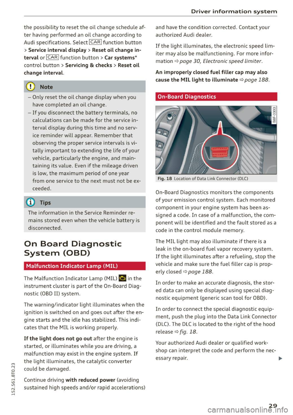
Fig. 18 Locat ion of Data Link Connector (DLC)
On-Board D iagnost ics monitors the components
of your emission control system. Each monito red
component in your engine system has been as
signed a code. In case of a malfunction, the com
ponent will be ident ified and the fault stored as a
code in the control module memory.
T he MIL light may also illum inate if there is a
leak in the on-board fuel vapo r recovery system .
If the light illuminates after a refueling, stop the
vehicle and make sure the fuel filler cap is prop
erly closed
¢ page 188.
In order to make an accurate diagnosis, the stor
ed data can only be displayed using special diag
nostic equipment (generic scan tool for OBD).
In order to connect the spec ial diagnostic equip
ment, push the plug into the Data Lin k Connec tor
(DLC). The DLC is located to the right of the hood
release
¢ fig. 18.
Your authorized Audi deale r or qualified work
shop can interpre t the code and perform the nec-
essary repair. .,,.
29
Page 37 of 264
M N
0 loo
rl I.O
"' N
"' rl
"'To lock the vehicle, close the door and touch
the sensor in the door hand le
once ¢ fig. 23
¢ A in General description on page 31 . Do not
reach inside the door handle.
The vehicle can be locked and unlocked at any
door. The remote control key cannot be more
than 1.5 m away from the door hand le. It makes
no difference whether the master key is in your
jacket pocket or in your brief case .
If you g rip the door handle while locking, this can
adversely affect the locking function.
It is not possible to re -open the door for a brief
pe riod directly after closing it . This allows yo u to
ensure that the doors are properly locked .
It depends o n the se ttings i n the radio or MM I*
whether the entire vehicle is un locked or one o f
the doors ¢
page 36.
A WARNING
Read and follow all WARNINGS ¢ A in Gener·
al description on page 31.
@ Tips
I f your vehicle has been stand ing fo r an ex
tended period, please note the following:
- The proximity sensors are deac tivated after
a few days to save power. Yo u then have to
pull on the door handle once to unlock the
vehicle and a second time to open the vehi
cle.
- To prevent the battery from being dis
charged and to preserve your veh icle's abili
ty to start for as long as possible, the ener
gy management system g radually switc hes
off unnecessary convenience functions. It is poss ible that you w ill not be ab le to unlock
you r vehicle using these convenie nce func
tions .
- Fo r Decla rat ion of Compliance to Uni ted
Sta tes FCC a nd Industry Canada regulations
~ page 24 7.
Open ing and clo sing
Locking and unlocking the vehicle from
inside
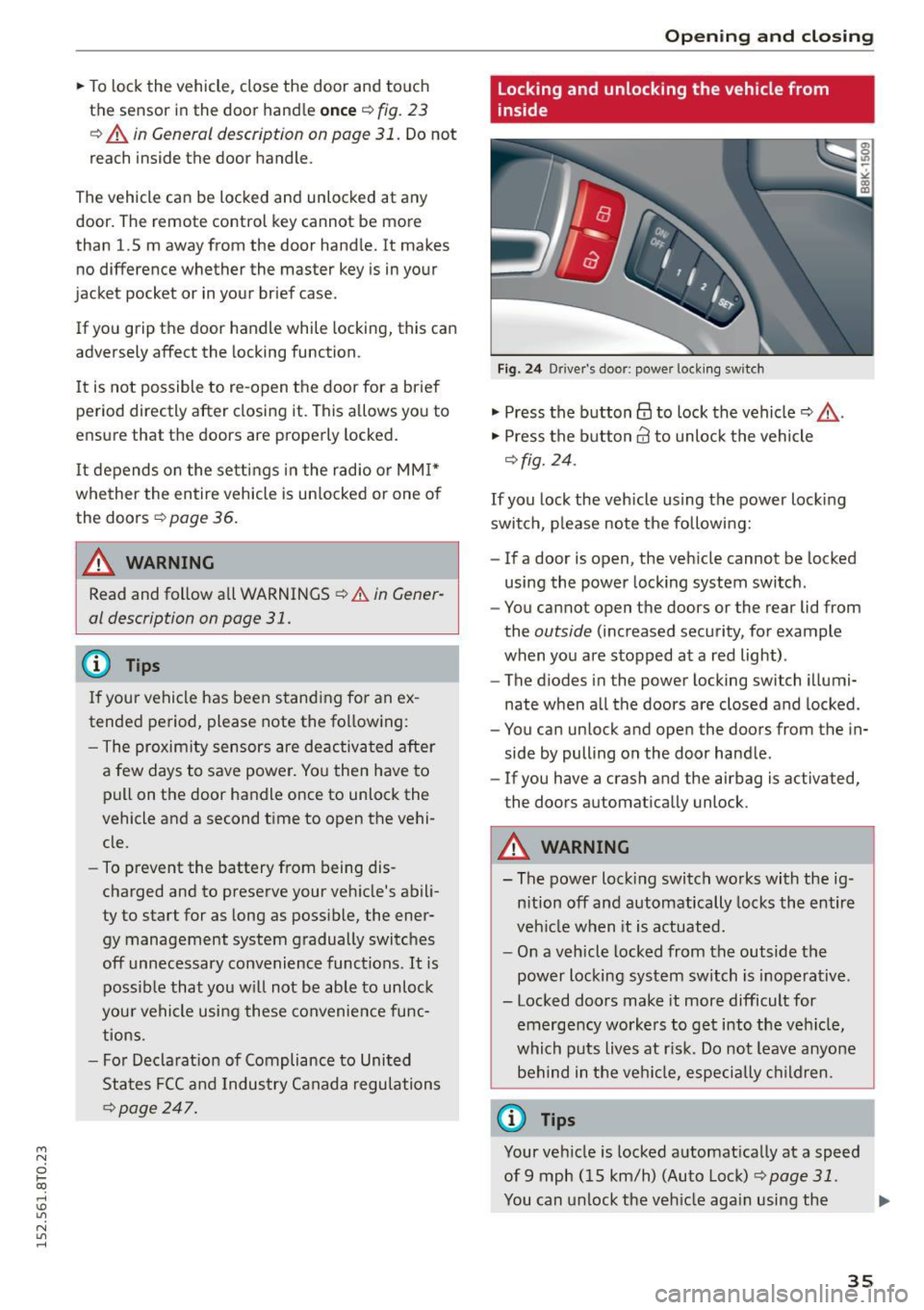
F ig. 2 4 Driver's door; power lock ing sw itch
"' Press the button@ to lock the vehicle¢_& .
"' Press the button@ to unlock the vehicle
¢fig. 24 .
If you lock the veh icle using the power loc king
swit ch, p lease note the following:
- If a door is open, the veh icle cannot be locked
using the power locking system switch .
- You cannot open the doors or the rear lid from
the
outside (increased security, for example
when you are stopped at a red light) .
- The diodes in the power locking switch illumi
nate when a ll the doors are closed and locked .
- You can unlock and open the doors from the in
side by pulling on the door hand le .
- If you have a crash and the airbag is activated,
the doors automa tically unlock .
A WARNING
-- The power lock ing switch works with the ig-
n ition off and automatically locks the entire
veh icle when it is actuated.
- On a vehicle locked from the outside the
power locking sy stem switch is inoperative .
- Locked doors make it more difficult for
emerge ncy worke rs to get into the veh icle,
which puts liv es at r isk. Do not leave anyone
be hind in the vehi cle, especially children .
@ Tips
Your vehicle is locked a utomat ically at a speed
of9 mph ( 15 km/h) (Auto Loc k)
¢ page 31.
You can unlock the veh icle aga in using the .,.
35
Page 77 of 264
M N
0 loo
rl I.O
"' N
"' rl
CD Note
If the engine has been under heavy load for
an extended period, heat builds up in the en
gine compartment after the engine is switch
ed off -there is a risk of damaging the engine .
Allow the engine to run at idle for about two
minutes before switching it off.
Convenience key
Starting the engine
Applies to vehicles: with conve nien ce key
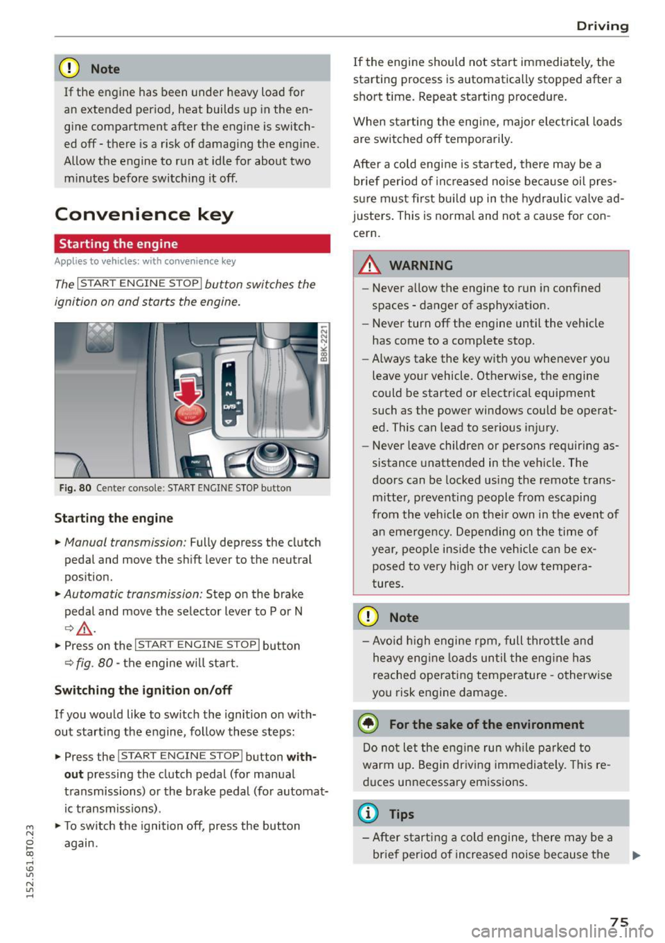
The I STAR T ENGINE ST OP I button switches the
ignition on and starts the engine.
Fig. 80 Ce nter console: START ENGINE STOP b utto n
Starting the engine
• Manual transmission: Fully depress the clutch
pedal and move the shift lever to the neutral
position.
• Automatic transmission: Step on the brake
pedal and move the selector lever to P or N
¢.&., .
.. Press on the I STAR T ENGINE ST OP I button
¢ fig . 80 -the engine w ill sta rt .
Switching the ignition on/off
If you would like to switch the ignition on with
out starting the engine, follow these steps:
• Press the
!START E NGINE STOPI button with
out pressing the clutch pedal (for manual
transmissions) or the brake pedal (for automat
ic transmissions) .
• To switch the ignition off, press the button
again.
Driving
If the engine should not start immediately, the
starting process is automatically stopped after a
short time. Repeat starting procedure.
When starting the engine, major elect rical loads
are switched off temporarily .
After a cold engine is started, there may be a
brief period of increased noise because oil pres
sure must fi rst bui ld up in the hydraulic valve ad
justers. This is normal and not a cause for con
cern.
.&_ WARNING
-~ ·
-Never allow the engine to run in confined
spaces - danger of asphyxiation.
- Never turn off the engine until the vehicle
has come to a complete stop.
- Always take the key with you whenever you
leave your vehicle. Otherwise, the engine
could be started or electrical equipment
such as the power windows could be operat
ed . This can lead to serious injury.
- Never leave children or persons requiring as
sistance unattended in the vehicle. The
doors can be locked using the remote trans
mitter, preventing people from escaping
from the vehicle on the ir own in the event of
an emergency. Depending on the time of
year, people inside the vehicle can be ex
posed to very high or very low tempera
tures.
CD Note
- Avo id high engine rpm, full throttle and
heavy eng ine loads until the engine has
reached operating temperature -otherwise
you risk engine damage.
@ For the sake of the environment
Do not let the engine run wh ile parked to
warm up. Begin driving immediately. This re
duces unnecessary emissions .
@ Tips
-After starting a cold engine, there may be a
brief period of increased noise because the
75
Page 78 of 264
Driving
oil pressure must first build up in the hy
draulic va lve adjusters. This is normal and
not a cause for concern .
- If yo u leave the vehicle with the ign ition
switched on, the ignition will switch off af
ter a certa in period o f time . P lease note that
electr ica l equipment suc h as exterior lights
will switch off as well when that happens.
Switching engine off
Applies to vehicles: w ith conven ience key
" Bring your veh icle to a complete stop .
" Automat ic transm iss ion: Move the se lector lev
er to the P or N pos ition .
" Press the
!S TAR T ENGINE STOPI bu tton
~page 75, fig. 80 .
Steering lock
The steering locks when you tu rn the engine off
using the
! STA RT E NG IN E STOP I button and open
the dr iver's door . The locked stee ring helps pre
vent vehicle theft .
Emergency off
If necessary, the eng ine can be sw itched off with
the selector lever in the R o r D/S pos itions . T he
engine stops if you press and hold the
I S TAR T ENGIN E ST OP I button at speeds be low
6 mph ( 10 km/h) and p ress the brake pedal.
A WARNING
- Never turn off the engine be fore the veh icle
has come to a comp lete stop. The f ull func
t ion of the b rake booster and the power
steering is not guaranteed. Yo u must use
more force to turn or bra ke if necessa ry. Be
ca use you cannot steer and b ra ke as you
usually wou ld, this could lead to c rashes
and serious injur ies .
- For safety reasons , you should always park
yo ur vehicle wi th the selec to r l ever in P . Oth
erwise, t he vehicle could inadve rten tly roll
away .
- T he rad iator fan ca n con tinue to run for up
to 10 m inutes eve n after yo u have tur ned
o ff the engine and removed the igni tion key .
T he r adiator fan c an also turn on ag ai n if t he
76
engine coolant heats up because of intense
sunlight or heat b uild- up in the eng ine com
partme nt.
- Always take the key w ith you whenever yo u
leave your vehicle . Otherwise, the engine
could be started or electrical equipment
such as the powe r windows could be operat
ed. This can lead to serio us i njur y.
(D Note
If the engine has been under heavy load for
an extended pe riod, heat bu ilds up in the en
gine compartment after the eng ine is switch
ed off -there is a risk of damaging the engine .
A llow the engi ne to run at id le for about two
m in utes before swit ching i t off.
Driver messages
Ignition is on
This message appears and a warning tone sound s
i f you open the d river's door when the ign ition is
switched on .
No key ident ified
This message appears when the
I S TAR T ENGINE ST OP I butto n is pressed if there
i s no maste r key ins ide the ve hicle or if the sys
tem does not recogni ze it. For examp le, the mas
ter key cannot be recogn ized if it is covered by an
object (e .g . a luminum brief case) wh ich
screens
the radio signal. Elect ro n ic dev ices such as cell
phon es can a lso inte rfe re with the radio signal.
Press brake pedal to start eng ine
This message appears if yo u do not press the
brake pedal to start the eng ine in a vehicle with
an a utomat ic transm ission.
Pre ss clutch pedal to start engine
This message appears if yo u do no t press the
cl utc h ped al to sta rt the eng ine in a ve hicle w it h
a manual transmission.
Shift to N or P to start eng ine
This message appears when attempt ing to star t
t h e engine if the selecto r lever for the automat ic
transmission is not in the P o r
N position. T he ..,.
Page 79 of 264
M N
0 loo
engine can only be sta rted w ith the selector in
these positions.
!!I Is the k ey in the vehi cle?
This message appea rs if the maste r key is re
moved from t he vehicle w ith the eng ine running.
If the maste r key is no longer in the vehicle, you
c a nnot swi tch on the ignition after s topping the
e ngine and yo u also cannot start the engine
again. Mo reover, yo u cannot lock the vehicle from
the outside with the key.
Shift to P otherwi se vehicle can roll aw ay. Doors
do not lo ck if lever i s not in P .
This message appears for safety reasons a long
w ith a warn ing signal. It appears if the se lector
l eve r fo r the autom atic transmis sion is not in the
P posi tion when switching off the ign ition. Move
the selector leve r to the P posit ion, otherwise the
ve hicle is not secured against ro lling away. You
a lso cannot lock the vehicle using the locking
button* on the door handle or using the remote
key .
Convenience key defective! Use ignition lock
This mes sage appea rs if the eng ine mus t be
started or s topped using the igni tion key and no t
the
! START ENGINE STOPI b utton.
Electromechanical
parking brake
Operation
The electromechanical parking brake replaces
the hand brake.
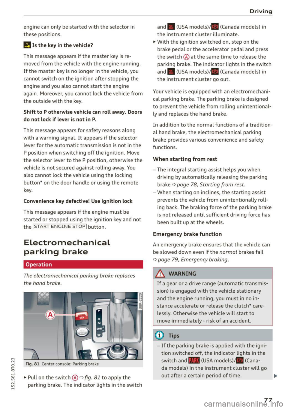
Fig. 81 Ce nter conso le : Park ing bra ke
rl
:5: .. Pull on t he sw itch @¢ fig. 81 to apply the
~ parking b rake. The indicator lights in the switch rl
Driv ing
and . (USA mode ls) . (Canada models) in
the instrument cluste r illuminate.
.. W ith the ignition switched on, step o n the
brake peda l or the accelerator pedal and press
the switch @ at the same time to release the
pa rking brake . The i ndicator lig hts in the sw itch
and . (USA models) . (Canada models) in
th e inst rument cluster go out .
Your vehicle is equipped with an electromechani
ca l park ing brake . T he pa rking brake is designed
to preve nt the vehicle from ro ll in g u nintent ional
ly and replaces the hand brake .
In add ition to the normal functions of a tradition
al hand brake, the electromechanical parki ng
brake p rov ides va rious conve nience and saf ety
funct ions.
When starting from rest
- The integral start ing ass ist helps you when
driving by automatically releasing the park ing
brake
¢ page 78, Starting from rest .
-When starting o n inclines, the starting assist
prevents the vehicle from unintentionally ro ll
ing back . The b rak ing force of the parking brake
i s not re leased until s ufficie nt driving force has
been built up at t he whee ls.
Emergency brake function
An emergency brake ensures that the vehicle can
be s lowed down even if t he
normal brakes fail
¢ page 79, Emergency braking .
A WARNING
If a gear or a drive ra nge (au tomati c tr an smis
s ion) is engaged w ith the vehi cle sta tion ary
a nd the e ng in e runn ing, you m ust in no in
stance ac ce lerate or re lease the cl utch* care
l essly. Otherwise the vehicle will start to
move immediately - risk of an accident.
(1) Tips
- If the p arking br ake is app lied wi th the ign i
tion sw itche d off, the ind icator lights in the
swit ch and -(USA mo dels)/ . (Cana
da mode ls) i n the instrument cluster will go
out after a certain per iod of t i me.
77
Page 89 of 264
M N
i? co ,...., \!) 1.1'1
N 1.1'1 ,....,
will return to automatic mode. To keep shifting
using the shift paddles, move the s elector lever
to the right out of the 0/5 position.
The t ransmission automatically shifts up o r down
before critica l engine speed is reached.
The transmission only allows manua l shift ing
when the engine speed is within the permitted range .
@ Tips
-When you sh ift into the next lower gear, the
transmission will downshift only when there i s no poss ibility of over -revving the engine.
- When the kick-down comes on, the trans
mission will sh ift down to a lower gear, de
pending on vehicle and engine speeds .
- Tiptronic is inoperat ive when the transmis
s ion is in the fa il-safe mode .
Kick-down
Appl ies to vehicles: with S tro nic/t iptronic
Kick-down enables maximum acceleration.
When you depress the accelerato r pedal beyond
the resistance po int, the automatic transm iss ion
downshifts into a lower gear, depend ing o n ve hi
cle speed and engine speed. The upsh ift into the
nex t higher gear ta kes place once the maximum
specified engine speed is reached .
A WARNING
Please note that the drive wheels can spin if
kick-down is used on a smooth slippery road -
there is a risk of sk idding.
Launch Control Program
App lies to vehicles: with S tro nic
Th e Launch Control Program provides the best
acceleration possible when starting from a stop .
Requirement: The engine must be at operating
temperature and the steering wheel must not be
turn ed .
.,. Press the
1.$ O FF I button ¢ page 171 while the
engine is running. The
II i ndicator light ill umi
nates i n the instrument cluster and
Stabiliza-
Aut omatic transm issio n
tion control (ESC): Sport. W arning! Re stri cted
s tability
appears in the driver information sys
tem display .
.,. Move the sele ctor leve r to the 0/5 position to
select spo rt mode (5) or se lect the
d y namic
driving mode in drive se lect* ¢ page 103 .
.,. Press the brake pedal strongly with your left
foot and ho ld it down fo r at least 1 second.
.,. At the same time, press the accelerator pedal
down comp lete ly with yo ur right foot u nti l th e
eng ine reaches and mainta ins a high R PM .
.,. Remove your foot from the brake pedal within 5
seconds ¢
,A.
A WARNING
-Always adapt your dr iving to the traff ic flow.
- Onl y use the Launch Cont ro l Program when
road and traffic cond itions allow it and oth
er drivers will not be endangered or annoyed by your driving and the vehicle's acce lera
tion .
- Please note that the driving wheels can spin
and the vehicle can break away when sport
mode is switched on, especially when the
road is s lippery .
- Once you have accelerated, you shou ld
sw itch sport mode off by pressing the
l.f3 OFF I button .
(D Tips
-The tra nsmission temperature may increase
signif icant ly after us ing the Launch Contro l
Program. If that happens , the program may
not be availab le for a few minutes.
It wi ll be
available again afte r a cool-down per iod.
- When acc elerating using the Launch Control
program, a ll vehicle parts are subject to
heavy loads. Thi s can resu lt in in creased
wear.
Transmission malfunction
App lies to vehicles : wi th S tronic/tip tro nic
[cjJ Tran smi ssion: Pre ss brake pedal and select
gear again . ..,.
87
Page 112 of 264
Parking Sy stem
Parallel Parking
App lies to vehicles: with parking system (rear, with rear view
camera)
Use parking mode 2 to help you park on the edge
of a street.
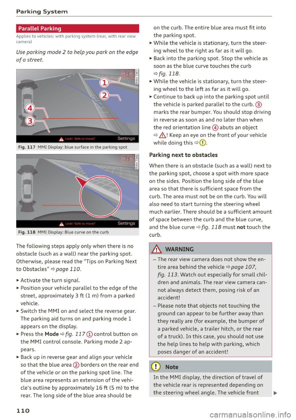
F ig. 117 MMI Display: bl ue s urface in the park ing spot
F ig. 118 MMI Display : B lue curve o n th e curb
The following steps apply only when there is no
obstacle (such as a wall) near the parking spot.
Otherwise, please read the "Tips on Parking Next
to Obstacles "
r::;, page 110.
.,. Activate the turn signal.
.,. Position your vehicle parallel to the edge of the
street, approx imately 3
ft (1 m) from a parked
vehicle .
.,. Swi tch the MMI on and se lect the reverse gear.
T he park ing aid tu rns on and parking mode 1
appears on the display.
... Press the
Mode r::;, fig. 117 © control button on
the MMI contro l conso le . Parking mode 2 ap
pears .
... Back up in reverse gear and align your vehicle
so that the blue area@ borders on the rear end
of the vehicle or on the park ing spot line . The
blue a rea represents an extension of the vehi
cle's outline by approximately 16
ft (5 m) to the
rear. The lo ng side of the b lue area should be
110
on the curb. The ent ire blue area must fit into
the parking spot.
... Wh ile the vehicle is stat ionary, turn the steer
ing wheel to the right as far as it will go.
.,. Back into the parking spot. Stop the vehicle as
soon as the blue curve touches the curb
,:;;, fig . 118 .
.,. Wh ile the vehicle is stationary, turn the steer
ing wheel to the left as far as it w ill go .
.,. Con tinue to back up into the p arking spot until
the vehicle is parked paralle l to the curb. ®
ma rks the rea r bumper. You should stop driving
in reverse as soon as and no later than when
the red orientation line @) abuts an object
r::;, _&! Keep an eye on the front of your veh icle
while doing this
r::;, Q) _
Parking ne xt to ob stacles
When there is an obstacle (such as a wall) next to
the parking spot, choose a spot wit h more space
on the sides. Position the long s ide of the blue
area so that there is sufficient space from the
curb. The area must not be on the curb . You will
also need to start turning the steer ing wheel
much earlie r. The re should be a sufficient amount
of space between the curb and the blue c urve,
and the blue curve
r::;, fig. 118 must not touch the
c u rb.
&_ WARNING
- T he rear view camera does not show the en
tire area beh ind the vehicle
r::;, page 107,
fig. 113 . Watch out especially for small chil
dren and anima ls . The rear view camera can
not a lways detect them, pos ing risk of an
accident!
- Please n ote that objects not touching the
ground can appear to be further away than
they really a re (for example, the bumper of
a parked veh icle, a tra iler hitch, or the rear
of a tr uck). In this ca se, yo u sh ould not us e
t he help lines to help with parki ng, which
poses dange r of an accident!
(D Note
In the MMI d isplay, the direction of travel of
the veh icle rear is rep resented depend ing on
the steer ing whee l ang le. The vehicle fron t
Page 259 of 264

Selective unlock feature . . . . . . . . . . . . . . . . . 36
Selector lever . . . . . . . . . . . . . . . . . . . . . . . . . 83
E mergency release . . . . . . . . . . . . . . . . . . . . 88
Selector lever emergency release . . . . . . . . . 88
Service and disposal Safety belt pretensioner . . . . . . . . . . . . . . 127
Service interval display . . . . . . . . . . . . . . . . . . 28
Service position
refer to Replacing wiper blades . . . . . . . . . 51
SE T button . . . . . . . . . . . . . . . . . . . . . . . . . . . 11
Shift indicator (efficiency program) . . . . . . . . 27
Shutting down vehicle . . . . . . . . . . . . . . . . . 178
Side airbags
Description . . . . . . . . . . . . . . . . . . . . . . . . . 145
How they work . . . . . . . . . . . . . . . . . . . . . . 147
side assist Adjusting the brightness . . . . . . . . . . . . . . 100
Sensor range . . . . . . . . . . . . . . . . . . . . . . . . 99
Side assist Activating and deactivating . . . . . . . . . . . . 100
Description . . . . . . . . . . . . . . . . . . . . . . . . . . 98
Side curtain airbags . . . . . . . . . . . . . . . . . . . 148
Description . . . . . . . . . . . . . . . . . . . . . . . . . 148
How they work . . . . . . . . . . . . . . . . . . . . . . 149
Safety instructions . . . . . . . . . . . . . . . . . . . 150
Side marker lights . . . . . . . . . . . . . . . . . . . . .
44
Ski sack . . . . . . . . . . . . . . . . . . . . . . . . . . . . . . 65
Snow chains . . . . . . . . . . . . . . . . . . . . . . . . . 220
Sound system display . . . . . . . . . . . . . . . . . . . 23
Sources of information about child restraints
and the ir use . . . . . . . . . . . . . . . . . . . . . . . . . 168
Spare tire . . . . . . . . . . . . . . . . . . . . . . . . . . . . 225
Speedometer . . . . . . . . . . . . . . . . . . . . . . . . . 12
Speed warn ing system . . . . . . . . . . . . . . . . . . 79
Sport differential . . . . . . . . . . . . . . . . . . . . . 102
Indicator lamp . . . . . . . . . . . . . . . . . . . . . . . 22
START ENGINE STOP button (convenience
key) . . . . . . . . . . . . . . . . . . . . . . . . . . . . . . . . . 76
START ENGINE STOP button (Convenience key) . . . . . . . . . . . . . . . . . . . . . . . . . . . . . . . . . 75
Starting from rest . . . . . . . . . . . . . . . . . . . . . . 78
Starting off with a trai ler . . . . . . . . . . . . . . . . 78
~ Start ing the engine . . . . . . . . . . . . . . . . . 72, 75
i? co ,...., \!) 1.1'1
N 1.1'1 ,....,
Index
Steering
Locking the steering . . . . . . . . . . . . . . . . . . 72
also refer to Electro-mechan ical power as-
sist .. .... .... .. ............. .... .. 174
Steering wheel Adjusting steering column . . . . . . . . . . . . . 72
Indicator light ... ................ 18, 174
Steps for determin ing correct load limit . . . 219
Stopping the engine . . . . . . . . . . . . . . . . . 74, 76
Storage . . . . . . . . . . . . . . . . . . . . . . . . . . . . . . 60
Storage compartments . . . . . . . . . . . . . . 61, 66
S tronic . . . . . . . . . . . . . . . . . . . . . . . . . . . . . . 82
Selector lever . . . . . . . . . . . . . . . . . . . . . . . . 83
S tronic transmission
Emergency release . . . . . . . . . . . . . . . . . . . . 88
Launch Control Program . . . . . . . . . . . . . . . 87
Sunroof
refer to Panoramic tilting sunroof . . . . . . . 40
Sun shades
Emergency closing (roof) . . . . . . . . . . . . . . .
40
Rear window . . . . . . . . . . . . . . . . . . . . . . . . . 49
Sun visors . . . . . . . . . . . . . . . . . . . . . . . . . . . . 49
Symbols
refer to Warning/indicator lights . . . . . . . . 13
T
Tachometer . . . . . . . . . . . . . . . . . . . . . . . . . . . 11
Technical data . . . . . . . . . . . . . . . . . . . . . . . . 241
T echnical modifications . . . . . . . . . . . . . . . . 246
Tether anchors . . . . . . . . . . . . . . . . . . . . . . . 166
Tether strap . . . . . . . . . . . . . . . . . . . . . . . . . 166
Tie-downs ...... .. ............. ... 65, 119
tiptronic . . . . . . . . . . . . . . . . . . . . . . . . . . . . . 82
Automatic Shift Lock (ASL) . . . . . . . . . . . . . 84
Driving . . . . . . . . . . . . . . . . . . . . . . . . . . . . . 84
Emergency mode . . . . . . . . . . . . . . . . . . . . . 87
Kick-down . . . . . . . . . . . . . . . . . . . . . . . . . . . 87
Manual shift program . . . . . . . . . . . . . . . . . 86
Selector lever . . . . . . . . . . . . . . . . . . . . . . . . 83
Tires ........ ... .. .. ................. 205
Low aspect ratio tires . . . . . . . . . . . . . . . . . 221
Replac ing . . . . . . . . . . . . . . . . . . . . . . . . . . 226
Service life . ... .. .. .............. ... 213
Tire pressure . . . . . . . . . . . . . . . . . . . . 215, 224
Tire pressure monitoring system . . . 222, 223
Tire pressure table . . . . . . . . . . . . . . . . . . . 216
257