interior lights AUDI A5 COUPE 2018 Owners Manual
[x] Cancel search | Manufacturer: AUDI, Model Year: 2018, Model line: A5 COUPE, Model: AUDI A5 COUPE 2018Pages: 409, PDF Size: 67.63 MB
Page 4 of 409
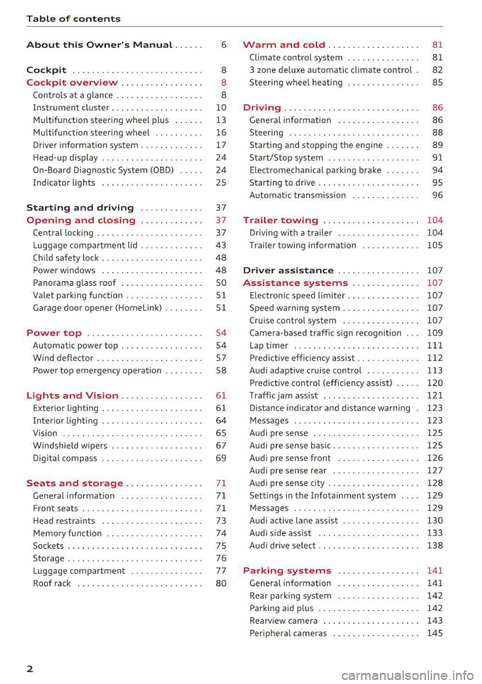
Table of content s
About this Owne r's Manual. . . . . .
6
Cockpi t . . . . . . . . . . . . . . . . . . . . . . . . . . . 8
Cockpit overview . . . . . . . . . . . . . . . . . 8
Controls at a glance . . . . . . . . . . . . . . . . . . 8
Instrument cluster . . . . . . . . . . . . . . . . . . .
10
Mu ltifunction steering wheel plus . . . . . . 13
Mu ltifunction steering wheel . . . . . . . . . . 16
Driver information system . . . . . . . . . . . . . 17
H ead-up display . . . . . . . . . . . . . . . . . . . . . 24
On-Board Diagnostic System (OBD) . . . . . 24
Indicator lights . . . . . . . . . . . . . . . . . . . . . 25
Starting and dri ving . . . . . . . . . . . . . 37
Opening and closing . . . . . . . . . . . . . 37
Cent ral locking . . . . . . . . . . . . . . . . . . . . . . 3 7
L ugg age compartment lid . . . . . . . . . . . . .
43
Ch ild safety lock . . . . . . . . . . . . . . . . . . . . . 48
Power windows . . . . . . . . . . . . . . . . . . . . . 48
Panorama glass roof . . . . . . . . . . . . . . . . . SO
Valet parking function . . . . . . . . . . . . . . . .
51
Garage door opener (Home link) . . . . . . . . 51
Power top . . . . . . . . . . . . . . . . . . . . . . . . 54
Automatic power top . . . . . . . . . . . . . . . . . 54
W ind deflector . . . . . . . . . . . . . . . . . . . . . . 57
Power top emergency operation . . . . . . . . 58
Lights and Vision . . . . . . . . . . . . . . . . . 61
Exterior lighting . . . . . . . . . . . . . . . . . . . . . 61
Interior lighti ng . . . . . . . . . . . . . . . . . . . . . 64
V1s1on . . . . . . . . . . . . . . . . . . . . . . . . . . . . .
65
W indshield wipe rs . . . . . . . . . . . . . . . . . . . 67
Dig it al c ompass . . . . . . . . . . . . . . . . . . . . . 69
Seats and storage................ 71
Gene ral information . . . . . . . . . . . . . . . . . 7 1
Fr ont seats . . . . . . . . . . . . . . . . . . . . . . . . . 71
H ead restra ints . . . . . . . . . . . . . . . . . . . . . 73
Memory function . . . . . . . . . . . . . . . . . . . . 7 4
Soc kets . . . . . . . . . . . . . . . . . . . . . . . . . . . . 75
Storage . . . . . . . . . . . . . . . . . . . . . . . . . . . . 76
Luggage compartment . . . . . . . . . . . . . . . 77
Roof rack . . . . . . . . . . . . . . . . . . . . . . . . . . 80
2
Warm and cold . . . . . . . . . . . . . . . . . . . 81
Climate contro l system . . . . . . . . . . . . . . . 81
3 zone deluxe automatic climate control 82
Steering wheel heat ing . . . . . . . . . . . . . . . 85
Driving ... .. .. .. .. .. ... .. ..... ... .. 86
Genera l information . . . . . . . . . . . . . . . . . 86
Steering . . . . . . . . . . . . . . . . . . . . . . . . . . .
88
Start ing and stopping the eng ine . . . . . . . 89
Start/Stop system . . . . . . . . . . . . . . . . . . .
91
E lectromechanical parking brake . . . . . . . 94
Starting to drive . . . . . . . . . . . . . . . . . . . . . 95
A utomat ic tra nsmission 96
Trailer towing . . . . . . . . . . . . . . . . . . . . 104
D riving with a tra ile r . . . . . . . . . . . . . . . . . 104
T ra ile r towing information . . . . . . . . . . . . 105
Driver assi stance . . . . . . . . . . . . . . . . . 10 7
Assistance systems . . . . . . . . . . . . . . 107
E lectronic speed limiter. . . . . . . . . . . . . . . 107
Speed warning system . . . . . . . . . . . . . . . . 107
Cruise contro l system . . . . . . . . . . . . . . . . 107
Camera-based traffic sign recognition . . . 109
Lap timer . . . . . . . . . . . . . . . . . . . . . . . . . . 111
Pred ictive effic iency assist........... .. 112
Audi adaptive cruise control . . . . . . . . . . . 113
Pred ictive cont rol (effic iency assist) . . . . . 120
T raffic jam assist . . . . . . . . . . . . . . . . . . . . 121
D ista nce ind icator and d ista nce wa rning 123
Messages . . . . . . . . . . . . . . . . . . . . . . . . . . 1 23
Audi pre sense . . . . . . . . . . . . . . . . . . . . . . 125
Audi pre sense basic . . . . . . . . . . . . . . . . . . 125
Audi pre sense front . . . . . . . . . . . . . . . . . 126
Audi pre sense rear . . . . . . . . . . . . . . . . . . 12 7
Audi pre sense city . . . . . . . . . . . . . . . . . . .
128
Settings in the Infotainment system . . . . 129
Messages . . . . . . . . . . . . . . . . . . . . . . . . . . 129
Audi active lane assist . . . . . . . . . . . . . . . . 130
Audi s ide ass ist . . . . . . . . . . . . . . . . . . . . . 133
Audi drive select . . . . . . . . . . . . . . . . . . . . . 138
Parking systems 141
General information . . . . . . . . . . . . . . . . . 141
Rear pa rking system . . . . . . . . . . . . . . . . . 142
Parking aid plus . . . . . . . . . . . . . . . . . . . . . 142
Rearview camera . . . . . . . . . . . . . . . . . . . . 143
Periphera l came ras . . . . . . . . . . . . . . . . . . 145
Page 39 of 409
Opening and closing
Central locking
Description
You can lock and unlock the veh icle centrally . You
have the following options:
-Remote control key¢ page 40,
-Sensors in the door handles* ¢ page 40,
-Lock cylinder on the driver's door c::> page 42,
or
-Interior central locking switch c::> page 41.
Turn signals
The turn s ignals flash twice when you unlock the
veh icle and flash once when you lock the veh icle.
If they do not flash, then one of the doors, the
rear lid or the hood is not closed.
Automatic locking (Auto Lock)
The Auto Lock funct ion locks all doors and the
luggage compartment lid once the speed has
ex
ceeded approximately 9 mph (15 km/h).
The vehicle can be unlocked if the opening func
tion in the central locking system sw itch is used
or one of the door handles is pulled.
In the event of a crash with airbag deployment,
the doors will a lso automat ically unlock to allow
access to the vehicle.
Selective door unlocking
The doors and luggage compartment lid will lock
when they close . You can set in the Infotainment
system whether
only the driver's door or the en
tire vehicle should be unlocked when unlocking
c::> page 41.
Unintentionally locking yourself out
Only lock your vehicle when all of the doors and
the luggage compartment lid are closed and the remote control key is not in the vehicle . This
helps to prevent you from locking yourse lf out
accidentally .
<( ~ The following cond it ions prevent you from lock-
"' ~ ing your remote control key in the vehicle:
.... 0 \0
3
-If the driver's door is open, the vehicle cannot
be locked by pressing the
fi'.) button on the re
mote contro l key or by touching the locking
sensor* on a door.
-If the most recently used convenience key* is
detected in the luggage compartment, the lug
gage compartment lid automatically unlocks
again after closing it.
-If the convenience key* that was last used is de
tected inside the vehicle, then the vehicle will
not be able to lock from the outside .
_& WARNING
---
-When you lock your vehicle from outs ide,
nobody- espec ially children
-should rema in
inside the vehicle. Remember, when you
loc k the vehicle from the outside the win
dows cannot be opened from the inside .
- When you leave the vehicle, always take the
ignit ion key with yo u. This will prevent pas
sengers (children, for examp le) from acci
dentally being locked in the vehicle should
they accidentally press the power locking
switch in the doors.
- Do not leave children inside the vehicle
un
supervised. In an emergency it would be im
possible to open the doors from the outside
without the key.
(D Tips
-Do not leave valuables unattended in the ve
hicle. A locked vehicle is not a safe!
-The LED in the driver's door rail blinks when
you lock the vehicle. If the LED lights up for
approximately 30 seconds after locking,
there is a malfunction in the central locking
system. Have the problem corrected by an
authorized Audi dealer or authorized Audi
Service Facility.
37
Page 53 of 409
Valet parking function
Applies to: vehicles wit h valet parking funct ion
The valet parking function protects the luggage
comportment from unauthorized access.
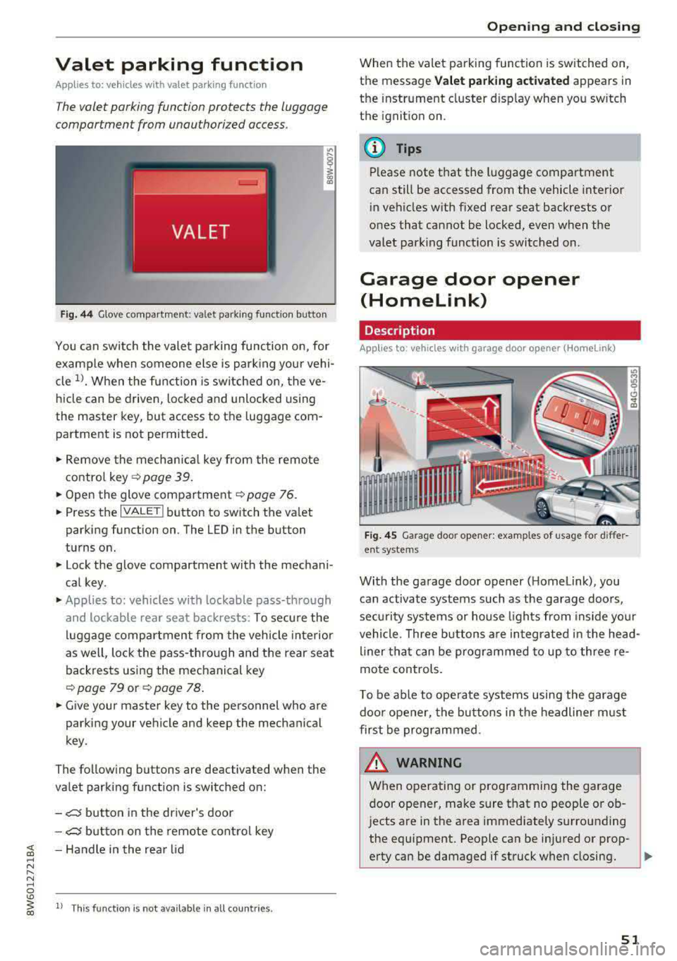
Fig. 44 Glove compartment: valet parking function butto n
You can switch the valet parking function on, for
example when someone else is parking your vehi
cle
l)_ When the function is switched on, the ve
hicle can be driven, locked and unlocked using
the master key, but access to the luggage com
partment is not permitted .
.,. Remove the mechan ical key from the remote
contro l
key~ page 39 .
.,. Open the glove compartment ~ page 76 .
.,. Press the IVALET I button to switch the valet
parking function on . The LED in the button
turns on.
.,. Lock the glove compartment with the mechani
cal key .
.,. Applies to: vehicles with lockable pass-through
and lockable rear seat backrests: To secure the
luggage compartment from the vehicle interior
as well, lock the pass-through and the rear seat
backrests using the mechanical key
~ page 79 or ~ page 78 .
.,. Give your master key to the personnel who are
parking your vehicle and keep the mechanical
key.
The following buttons are deactivated when the
va let parking function is switched on:
-,c:;5 button in the driver's door
-,c:;5 button on the remote control key
~ -Handle in the rear lid ..... N
" N ..... 0
'° ~ ll Th is function is not available in all countr ies . co
Open ing and closing
When the valet parking function is switched on,
the message
Valet parking activated appears in
the instrument cluster disp lay when you sw itch
the ignition on.
@ Tips
Please note that the luggage compartment
can still be accessed from the vehicle interior
in vehicles with fixed rear seat backrests or
ones that cannot be locked, even when the
valet park ing funct ion is switched on.
Garage door opener
(Homelink)
Description
Applies to: vehicles with garage door opener (Home Link)
Fig. 45 Garage door opener: examples of usage for differ
ent system s
With the garage door opener ( Homelink), you
can activate systems such as the garage doors,
sec urity systems or house lights from inside your
vehicle. Three buttons are integrated in the head
liner that can be programmed to up to three re
mote controls.
T o be able to operate systems using the garage
door opener, the buttons in the headliner must
first be programmed .
_& WARNING ~
When operating or programming the garage
door opener, make sure that no people or ob
jects are in the area immediately s urrounding
the equipment. People can be injured or prop-
erty can be damaged if struck when closing.
Ill>
51
Page 65 of 409
• Headlight assista nt: m alfun cti on! See own
e r's manual
Drive to an autho rized Aud i deale r or a uthorized
Aud i Service Facility immedia tely to have the
malfunct ion corrected. You can still switch the
high beams on or off manually.
• Headlight a ssi stant : currently unavailabl e.
C amera view re stricted due to surrounding s.
See owne r's manual
The camera view is b locked, fo r example by a
sticker o r debris.
The sensor is located between the interior rear
view mirror and the windshield . Do not place any
stickers in th is area on the wi ndsh ield .
& WARNING
High beam assistan t is only i ntended to assist
the drive r. The dr iver is still responsible for
controlling the headlights and may need to
switch them on and off manually depend ing
on light and visibility conditions. It may be
necessary to ope rate them manually in s itua
tions such as:
- In adverse weather conditions such as fog, heavy ra in, b low ing snow or spraying water .
- On roads where oncoming traffic may be
partially obsc ured, such as expressways.
- When there are road users that do not have
su fficient lighting, s uch as bicyclers or
vehicles with dirty ta il lamps.
- In tight cu rves and on steep hills .
- In poorly lit areas.
- Wi th strong ref lec to rs , such as s igns.
- If the area of the windsh ield near the senso r
is f ogged ove r, dirty, icy or covere d wi th a
st icker.
Adjusting the exterior lighting
The functions ore adjust ed in the Infotainment
system.
• Select in the Info tainment system : IM ENUI but-
~ ton >Vehicle > left contro l button > Vehicle ~
~ setting s> Exterior lighting . N ~ 0
'° ~ co
Lights and Vision
Automatic headlights
You can adjust the following se ttings in the Au
t o matic headlights
menu :
Activation tim e -you can adjust if the headlights
switch on
Early , Medium or Late accord ing to the
sensit ivi ty of the light sensor .
Headlight assistant * -you can switch the high
beam assistant* on and off.
Entry /exit lighting
When it is dark, the Ent ry /e xit lighting ill umi
nates the area around the vehicle when unlocking
the vehicle and after switching off the ignit ion
and opening the dr iver's door .
The
Entry /exit lighting only works when it is
dark and the light sw itch is in the
AUTO position.
Daytime running l ight s
USA model s:
the daytime running lights can be
switched on/off . Sel ect
On or Off.
Canad a model s:
this f unction canno t be switched
off. They activate automatically eac h time the ig
nition is switched on .
Emergency flashers
-- ---
] -~ ~-
--------
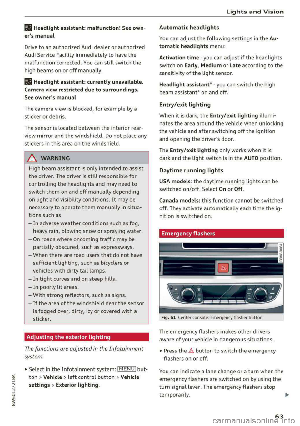
Fig . 61 Ce nte r con so le: emergency flas her butto n
T he emergen cy flashe rs makes othe r d rivers
aware of your vehicle in dangerous situat ions.
• Press the 11 b utton to switch the emergency
flashe rs on or off .
You can ind icate a lane change or a turn when the
eme rgency flashers are switched on by using the
tu rn s ignal lever. The emergency flashe rs stop
tempora rily.
.,.
63
Page 66 of 409
Lights and Vision
The emergency flashers also work whe n the igni
tion is turned off.
@ Tips
You s hou ld sw itch the emergency flashers on
if:
- you are the last car in a traff ic jam so that
a ll other vehicles approaching from behind
can see you, or if
- your ve hicle has bro ke n down or you are
having an eme rgency, or i f
- you r vehicle i s being towed or if yo u are tow
ing another vehicle
Interior lighting
Front interior lighting
F ig. 62 Headliner: front inter ior l ight ing (example)
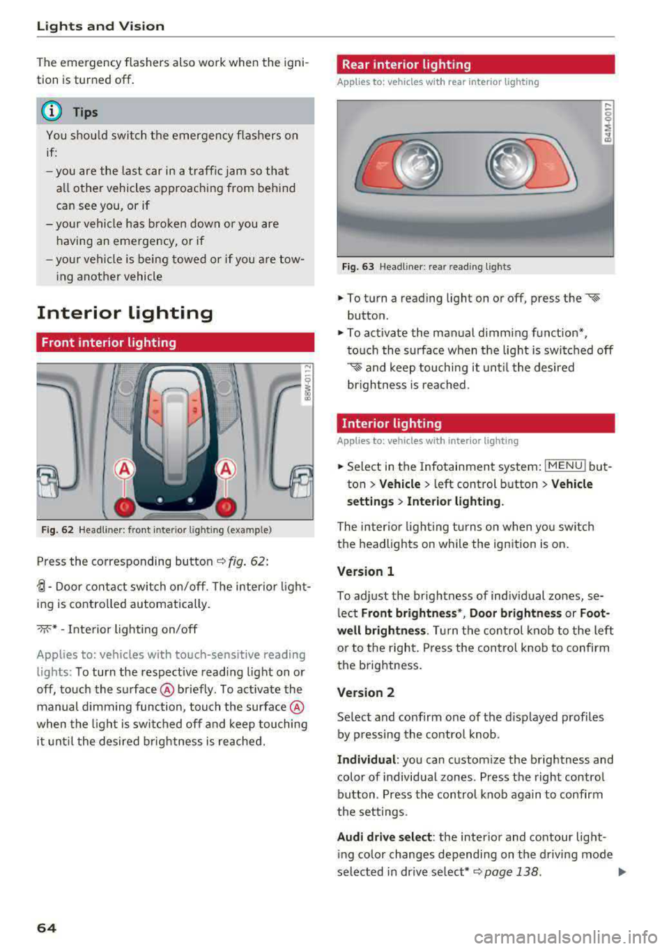
Press the corresponding button c::> fig . 62:
~-Door contac t switch on/off. The interior ligh t
ing is controlled automatically.
->;<-* -Inte rior l ighting on/off
Applies to: vehicles with touch-sensitive reading
lights: To turn the respect ive reading light on or
off, touch the surface @ briefly . To activate the
manual dimming function, touch the surface @
when the light is swi tched off and keep touching
it unt il t he desired brig htness is reached.
64
Rear interior lighting
Applies to: vehicles with rear interior lighting
Fig. 63 Headline r: rear reading lights
.,. To turn a reading light on or off, press the «~
button .
.,. To activate the ma nual dimming f unction*,
t o uch the s urface when the light is swi tc h ed off
'* and keep touching it unt il the desired
brightness is rea ched.
Interior lighting
Applies to: vehicles with interior lighting
.,. Select in the Infotainment system : IMENUj but
ton
> Vehicle > l eft control b utton > Vehicle
s etting s
> Interior lighting.
The inter io r l ight ing turns on when you sw itch
the headlights on w hile the ignition is on.
Version 1
To adjust the brightness of indiv idual zones, se
l ect
Front brightne ss*, Door brightnes s or Foot
well brightness .
Tur n the control kno b to the left
or to the right. Press the con trol knob to confirm
the b rightness.
Version 2
Se lect and confirm one of the d isplayed p rofiles
by pressing the con tro l knob.
Individual : you can custom ize the brightness and
color of individual zones. Press the right contro l
button. Press the control knob aga in to confirm
the set tings .
Audi driv e sel ect : the interio r and contour lig ht
i ng color changes depending on the d riving mode
selected in dr ive se lect*
c::> page 138 . ..,.
Page 68 of 409
Lights and Vision
make objects in the mirror appear smaller
and farther away. Your may estimate incor
rectly when you use these mirrors to gauge
your distance from the vehicles behind you
when changing lanes, which increases the risk of an accident.
{U) Note
- Applies to vehicles with power folding exte rior mirrors: if the mirror housing was
moved by outside forces (such as an impact
when maneuvering), you must use the pow
er folding function to fold the mirror all the
way out. The mirrors will make a loud noise
when they latch into place. The mirror hous
ing must not be moved back into place by
hand because this would impair the func
tion of the mirror mechanism.
- Applies to vehicles without power folding exterior mirrors: if the mirror housing was
moved by outside forces (such as an impact
when maneuvering), you must move it back
in place by hand.
- If you wash
th@ vehicle in an automatic car
wash, you must fold the exterior mirrors in
to reduce the risk of damage to the mirrors.
Never fold power folding exterior mirrors*
by hand . Only fold them in and out using
the power controls.
@ Tips
-If the power adjusting function malfunc
tions, the glass in both mirrors can be ad
justed by pressing on the edge of it by hand.
- The exterior mirror settings are stored with
the memory function*
9 page 74.
Dimming the mirrors
Your vehicle is equipped with a manual or auto
matic* dimming rearview mirror.
Manual dimming rearview mirror
.,. Pull the lever on the bottom of the mirror back.
66
Automatic dimming rearview mirror*
.,. The interior and exterior mirrors dim automati
cally when light shines on them, for example
from headlights on a vehicle behind you.
A WARNING
If the glass on an automatic dimming mirror
breaks, electrolyte can leak out. This liquid
can irritate the skin, eyes and respiratory sys
tem. If there is contact with the fluid, flush
immediately with plenty of water. Consult a
physician if necessary.
- Repeated or long-term exposure to electro lyte fluid can lead to irritation of the air
ways, especially in people with asthma or
other respiratory conditions. Take deep
breaths immediately after leaving the vehi
cle or, if this is not possible, open all of the
doors and windows as wide as possible.
- If electrolyte fluid enters the eyes, flush
them thoroughly with a large amount of
clean water for at least 15 minutes and then
seek medical attention.
- If electrolyte fluid comes into contact with
the skin, flush the affected area with clean
water for at least 15 minutes and then clean
with soap and water and seek medical at
tention. Clean affected clothing and shoes
thoroughly before wearing again.
- If the fluid was swallowed and the person is
conscious, flush the mouth with water for at least 15 minutes. Do not induce vomiting
unless this is recommended by medical pro
fessionals. Seek medical attention immedi
ately .
([) Note
If the glass on an automatic dimming mirror
breaks, electrolyte can leak out. This liquid
damages plastic surfaces and paint. Clean
this liquid as quickly as possible, for example
with a wet sponge.
(D Tips
- If the light reaching the rearview mirror is
obstructed, the automatic dimming mirror
will not function correctly,
Page 69 of 409

-The automatic dimming mirrors do not dim
when the interior lighting is turned on or
the reverse gear is selected.
Sun visors
9 :a
W- -- ----___._, dri~
Fig. 66 Su n visor
Sun visor
The sun visors for the driver and front passenger
can be re leased from their mounts and turned to
ward the doors
¢ fig. 66 @.
They can a lso be moved back and fo rth le ngth
wise in this posit ion.
Vanity mirror
The mirror lighting* switches on when the cover
over the vanity mirror @opens .
Windshield wipers
Switching the wipers on
Fig. 67 Windshield w iper lever
Move the windshield wiper lever to the corre
spond ing pos ition:
@ -Windshield wipers off
en 0 0
> u. III
@ -Rain sensor mode. The windshield wipers
switch on once the vehicle speed exceeds approx-
Lights and V ision
imately 2 mph (4 km/h) and it is raining. The
higher the sensitivity of the rain sensor that is set
(switch @to the right), the earlier the w ind
shield wipers react to moisture on the wind
shield. You can deactivate the rain sensor mode in the Infotainment system, wh ich sw itches the
intermittent mode on. To do this, select:
IMENUI
button > Vehicle > left control button > Driver
a ss istance > Rain sensor .
In inte rmittent mode,
you can adjust the interval time using the switch
@.
@ -Slow wiping
®-Fast wiping
@ -Single wipe. If you ho ld the lever in this posi
t ion longer, the wipers switch from slow wip ing
to fast wiping.
® -Clean the windshield . The wipers wipe one
time after several seconds of driving to remove
water droplets. You can sw itch this function off
by moving the lever to posit ion ® within
10 sec
onds of the afterwipe. The afterwipe function is
reactivated the next time you switch the ignit ion
on.
Clean the headlights*. The headlight washer sys
tem* operates only when the low beam head lights are on. If you move the lever into position
@, the headlights will be cleaned at fixed inter
vals .
_&. WARNING
-The rain sensor is on ly intended to ass ist the
d river. The driver may sti ll be responsible
for manually switching the wipers on based on visibility conditions.
-The windsh ield may not be treated w ith wa
ter-repelling windshield coating agents. Un
favorable conditions, such as wetness, dark
ness or low sun, can result in increased
g lare, which increases the risk of an acci
dent. Wiper blade chatter is also possible.
-Properly functioning windshield wiper
blades are required for a clear v iew and safe
driving
c;, page 68, Replacing wiper
blades .
~
67
Page 95 of 409
@j indicator light appears in the instrument clus
ter disp lay, the engine will not be stopped, for
examp le in the following situations:
- T he eng ine has not reached the minimum re
quired temperature for Start/Stop mode.
- T he interior temperature selected by the cli-
mate contro l system has not been reached .
- T he outs ide temperature is ext remely h igh/low.
- The windshield is being defrosted.
- The neck heating* is turned on .
- The vehicle battery charge level is too low.
- The steering wheel is turned at a sharp angle or is moving .
- After engaging the reverse gear.
- On sharp inclines.
- At high altitudes .
Engine automatically restarts
The standard Start/Stop mode will be canceled
during a stop phase in the follow ing s ituations .
The engine resta rts without any action by the
driver.
- The vehicle rolls , for example while on a slope.
- The interior temperature differs from the tem-
perature selected in the A/C system .
- The windshield is being defrosted.
- The brake pedal is pressed several times in a
row.
- The vehicle battery charge level is too low .
- Power consumption is high.
The engine can turn off again when the condi
tions for Start/Stop mode are met.
Ignition is switched off automatically
To prevent the vehicle battery from draining, the
ignition will switch off automat ically under the
following conditions :
- The Start/Stop system has stopped the engine .
- The vehicle is stationary.
- You left the ve hicle and the engine was not re-
started within approximate ly 30 seconds .
If th is happens, you w ill see the message
Igni
<( ~ tion turns off automatically in the instrument
~ cluster and the activated low beams are replaced N
8 by the parking light. The parking lights will \0
3
switch off after approximately 30 minutes or
when you lock the vehicle .
T he ign ition also switches off when you lock the
vehicle from the outside during a stop phase.
If the Start/Stop system has not turned off the
engine or if you have switched the Start/Stop sys
tem off manually, the ignition w ill no t be auto
matically sw itched off and the eng ine will contin
ue to
run ¢& .
A WARNING
To reduce the risk of poisoning, never allow
the engine to run in confined spaces.
(D Tips
Applies to: vehicles with automatic transmissions
- If you leave the vehicle with the 0/5 or R se
lector lever position engaged, the parking
brake is automatically set.
- If you select the D or N selector lever posi
tion after shifting into reverse, the vehicle
must be driven faster than 6 mph (10 km/h)
in order for the engine to switch off again .
Manually switching the Start/Stop system
off/on
Applies to: veh icles w ith Start/Stop system
If you do not wish to use the system, you can
switch it off manually.
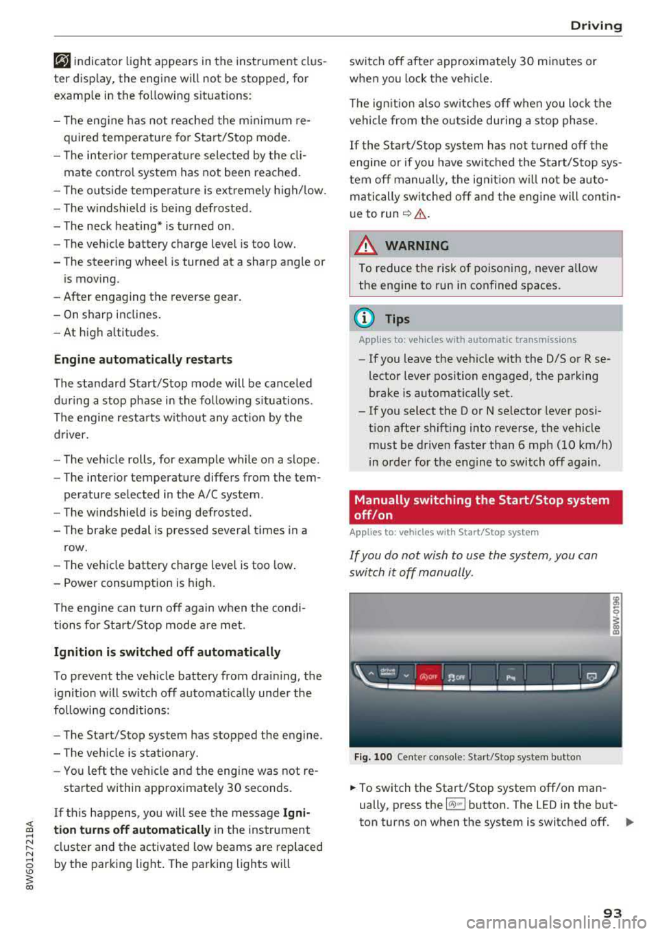
Fig. 100 Center co nsole: Start/Stop system butto n
-
.,. To switch the Start/Stop system off/on man
ually, press the
l (A) ml button. The LED in the but
ton turns on when the system is switched off.
Ill-
93
Page 379 of 409
Fuses a nd bul bs
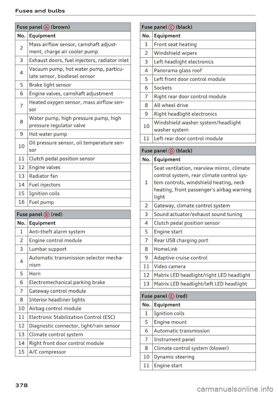
Fuse panel @ (brown) Fuse panel© (blac k)
No. Equip ment No. Equipm ent
2
Mass airflow sensor, camshaft adjust-
ment, charge air cooler pump 1 F ront seat heating
2 Windshield wipers
3 Exhaust doors, fuel injectors, radiator inlet 3 Left head light electronics
4 Vacuum pump , hot water pump, particu-
late sensor, biodiesel sensor 4 Panorama glass roof
s Left front door contro l module
5 Brake light sensor 6 Sockets
6 Engine valves, camshaft adjustment 7 Right rear door control mod ule
7
Heated oxygen sensor, mass airflow sen-8 All wheel drive
sor
8
Water pump, high pressure pump, high
pressure regulator valve
9 Hot water pump
9 Right headlight electronics
10
Windshield washer system/headlight
washer system
11 L eft rear door control module
10
Oil pressure sensor, oil temperature sen-
sor
Fu se panel @ (blac k)
11 Clutch pedal position sensor No. Equipmen t
12 Engine valves
Seat ventilation, rearv iew mirror, climate
13 Rad iator fan control system, rear climate control sys-
14 Fuel injectors
15 Ignition
coils
16 Fuel pump
1 tern controls , windsh ie ld heat ing , neck
heating, front passenger 's airbag warning
light
2 Gateway, climate control system
Fuse panel@ (red ) 3 Sound actuator/exhaust sound tuning
No. Equ ip me nt 4 Clutch pedal posit ion sensor
1 Anti-theft alarm system 5 Engine start
2 Engine control module 7 Rear USB charg ing port
3 Lumbar support 8 Homelink
4 Automatic transmission selector mecha-
nism 9 Adaptive cruise contro l
11 Video camera
5 Horn 12 Matrix LED headlight/right L ED headlight
6 Electromechan ica l park ing brake 13 Matrix LED headlight/left LED headlight
7 Gateway control module
8 Interior headl iner lights
10 Airbag control module
11 Electronic Stabilization Control (ESC)
Fuse panel © (red )
N o. Equ ipmen t
1 Ign ition co ils
12 Diagnostic connector, light/rain sensor
13 Climate control system
14 Right front door control module
lS A/C compressor
5 Engine mount
6 Automatic transmission
7 Instrument panel
8 Climate control system (blower)
10 Dynamic steering
11 Engine start
378
Page 383 of 409
Emergency situations
@ Tips
The discharged battery must be properly con
nected to the vehicle's electrical system .
When jump starting or charging the battery,
never connect the negative ground cable to
the battery negative post because the battery
manager system must be able to detect the
battery's state of charge. Always connect the
negat ive ground cable to the negative ground
pos t of the battery manager control unit.
Using the jump start
cable
Both jump start cables must be connected in the
correct order!
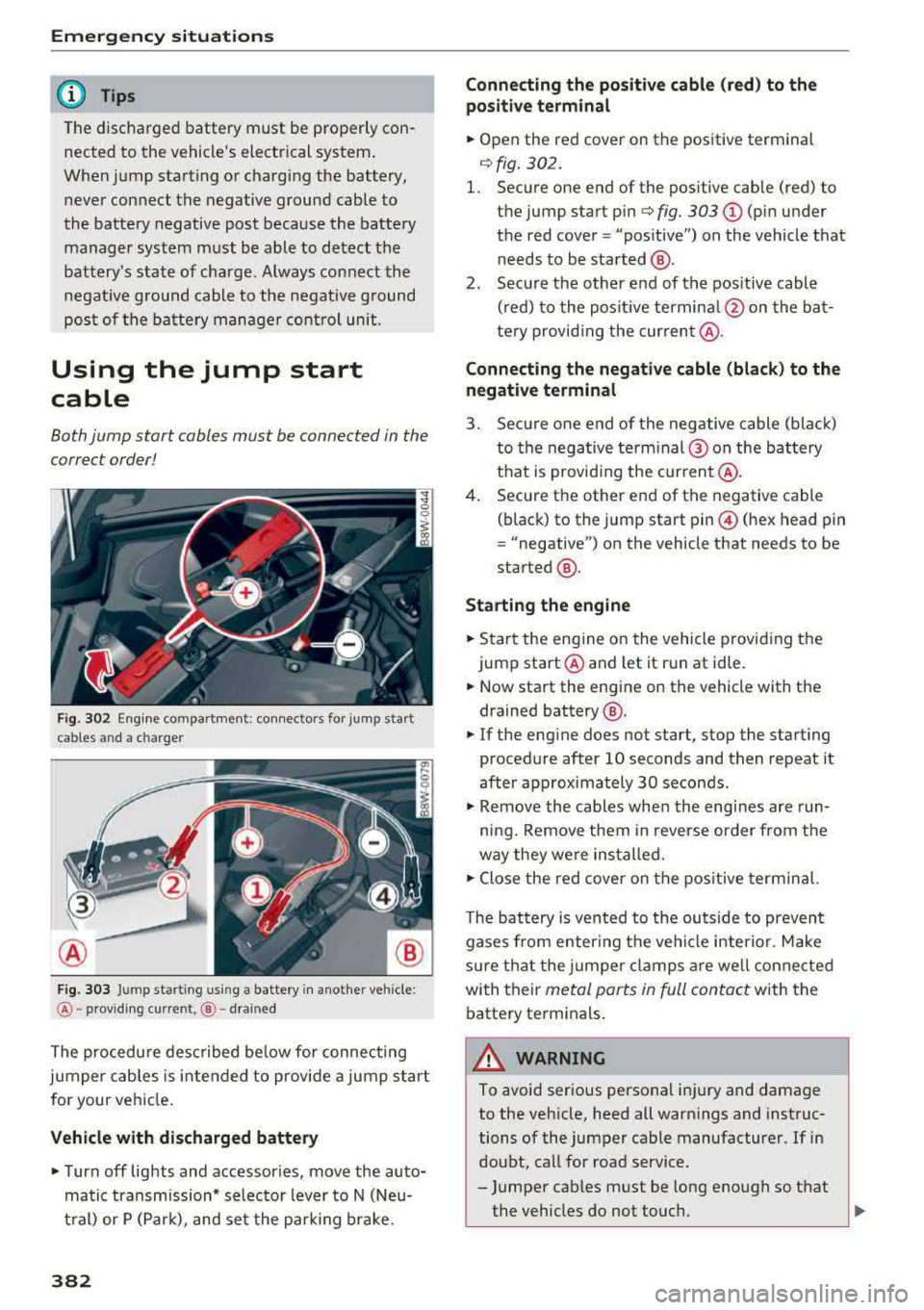
Fig. 302 Engin e compartme nt: co nn ectors for jump start
cables and a charger
Fig. 303 Jump starting using a battery in anot her vehicle:
@-pro vidi ng current, @-drained
The procedure desc ribed be low for connecting
jumper cables is intended to provide a jump start
for your vehicle.
Vehicle with discharged battery
... Turn off lights and accessories, move the auto
matic transmission* selector lever to N (Neu
tral) or P (Park), and set the park ing brake.
382
Connecting the positive cable (red) to the
positive terminal
... Open the red cover on the positive terminal
¢fig. 302.
1. Secure one end of the positive cable (red) to
t he jump start
pin¢ fig. 303 CD (pin under
the red cover = "pos itive") on the vehicle that
needs to be started @.
2. Secure the other end of the positive cable
(red) to the positive terminal @on the bat
tery provid ing the cur rent @.
Connecting the negative cable (black) to the
negative terminal
3. Secure one end of the negative cable (black)
to the negative terminal @ on the battery
that is providing the current @.
4. Secure the other end of the negative cable
(black) to the jump start
pin @ (hex head pin
= "negative") on the vehicle that needs to be
started @.
Starting the engine
... Start the eng ine on the vehicle providing the
jump start @and let it run at idle .
... Now start the engine on the vehicle with the
drained battery @.
... If the engine does not start, stop the starting
procedure after 10 seconds and then repeat it
after approximately 30 seconds .
... Remove the cables when the engi nes are run
ning. Remove them in reverse order from the
way they were installed.
" Close the red cover on the positive terminal.
The battery is vented to the outside to prevent
gases from enter ing the vehicle interior. Make
sure that the jumper clamps are well connected
with their
metal parts in full contact with the
battery terminals .
A WARNING
To avoid serious personal injury and damage
to the vehicle, heed all warnings and instruc
tions of the jumper cable manufacturer. If in
doubt, call for road service .
- Jumper cables must be long enough so that
the vehicles do not touch.
"'