ECU AUDI A6 1995 C5 / 2.G ATQ Engine Motronic Injection System Servicing Workshop Manual
[x] Cancel search | Manufacturer: AUDI, Model Year: 1995, Model line: A6, Model: AUDI A6 1995 C5 / 2.GPages: 78, PDF Size: 1 MB
Page 1 of 78
24-1
Motronic injection system,
servicing
Safety precautions
If special testing equipment is required during
road test, note the following:
WARNING!
Scan tools and testing devices must always
be secured on the rear seat and operated
from there by a second person.
If a scan tool or testing device were to be
operated from the passenger seat and there
were an accident involving activation of the
passenger-side airbag, the person seated
there could be seriously injured.
To reduce the risk of personal injury and/or
damage to the fuel injection and ignition system,
always observe the following:
Only disconnect and reconnect wires for
injection and ignition system, including test
leads, when ignition is turned off.
If engine is to be cranked at starting RPM
without starting (e.g. for compression testing),
Pa
ge 1 of 78 Motronic in
jection s
ystem, servicin
g
11/23/2002 htt
p://127.0.0.1:8080/audi/servlet/Dis
play?action=Goto&t
yp
e=re
pair&id=AUDI.B5.FU05.24.1
Page 14 of 78
24-12
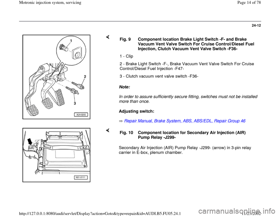
Note:
In order to assure sufficiently secure fitting, switches must not be installed
more than once.
Adjusting switch:
Repair Manual, Brake System, ABS, ABS/EDL, Repair Group 46
Fig. 9 Component location Brake Light Switch -F- and Brake
Vacuum Vent Valve Switch For Cruise Control/Diesel Fuel
Injection, Clutch Vacuum Vent Valve Switch -F36-
1 - Clip
2 - Brake Light Switch -F-, Brake Vacuum Vent Valve Switch For Cruise
Control/Diesel Fuel Injection -F47-
3 - Clutch vacuum vent valve switch -F36-
Secondary Air Injection (AIR) Pump Relay -J299- (arrow) in 3-pin relay
carrier in E-box, plenum chamber. Fig. 10 Component location for Secondary Air Injection (AIR)
Pump Relay -J299-
Pa
ge 14 of 78 Motronic in
jection s
ystem, servicin
g
11/23/2002 htt
p://127.0.0.1:8080/audi/servlet/Dis
play?action=Goto&t
yp
e=re
pair&id=AUDI.B5.FU05.24.1
Page 18 of 78
24-16
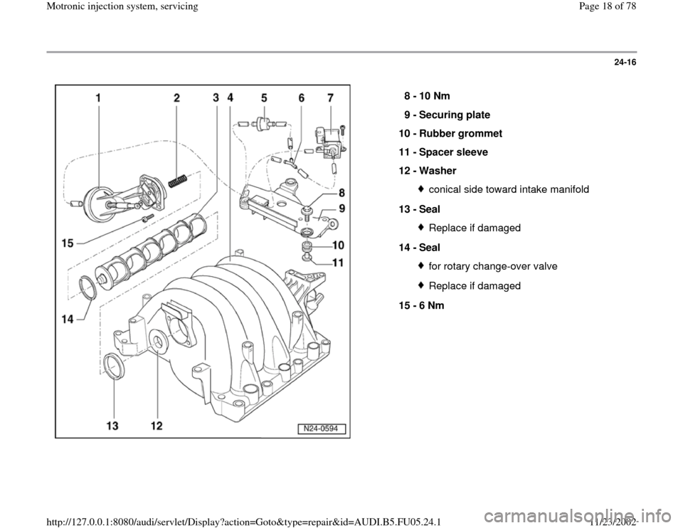
8 -
10 Nm
9 -
Securing plate
10 -
Rubber grommet
11 -
Spacer sleeve
12 -
Washer
conical side toward intake manifold
13 -
Seal Replace if damaged
14 -
Seal for rotary change-over valveReplace if damaged
15 -
6 Nm
Pa
ge 18 of 78 Motronic in
jection s
ystem, servicin
g
11/23/2002 htt
p://127.0.0.1:8080/audi/servlet/Dis
play?action=Goto&t
yp
e=re
pair&id=AUDI.B5.FU05.24.1
Page 49 of 78
24-41
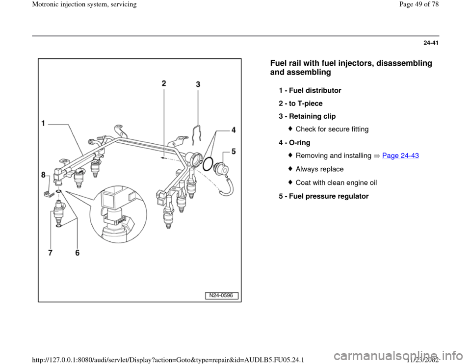
Fuel rail with fuel injectors, disassembling
and assembling
1 -
Fuel distributor
2 -
to T-piece
3 -
Retaining clip
Check for secure fitting
4 -
O-ring Removing and installing Page 24
-43
Always replaceCoat with clean engine oil
5 -
Fuel pressure regulator
Pa
ge 49 of 78 Motronic in
jection s
ystem, servicin
g
11/23/2002 htt
p://127.0.0.1:8080/audi/servlet/Dis
play?action=Goto&t
yp
e=re
pair&id=AUDI.B5.FU05.24.1
Page 52 of 78
24-44
- Disengage retaining clip and remove fuel
injector.
Note:
Fuel lines must be disconnected before replacing
fuel distributor.
Installation is reverse of removal, noting the
following:
Remove O-rings at all opened connections.
(Never remove plastic cap from valve head
to replace front O-ring - pry O-ring off over
plastic cap).
Lightly lubricate O-rings with clean engine
oil.
Make sure fuel injectors are in place and
seated correctly
Check clip for unobstructed fitting.
Place fuel rail with secured fuel injectors
onto intake manifold, and apply uniform
pressure to press it in.
Tightening torque
Pa
ge 52 of 78 Motronic in
jection s
ystem, servicin
g
11/23/2002 htt
p://127.0.0.1:8080/audi/servlet/Dis
play?action=Goto&t
yp
e=re
pair&id=AUDI.B5.FU05.24.1