check engine light AUDI A6 1995 C5 / 2.G ATQ Engine Motronic Injection System Servicing Workshop Manual
[x] Cancel search | Manufacturer: AUDI, Model Year: 1995, Model line: A6, Model: AUDI A6 1995 C5 / 2.GPages: 78, PDF Size: 1 MB
Page 22 of 78
24-20
Important note:
After re-connecting the Engine Control Module (ECM), the following work
steps must be performed:
- Check DTC memory and erase it if necessary Page 01
-15
.
- Perform adaptation of the Throttle Valve Control Module -J338- Page
24
-142
.
Note:
In the first adaptation phase during engine basic setting, it is possible that
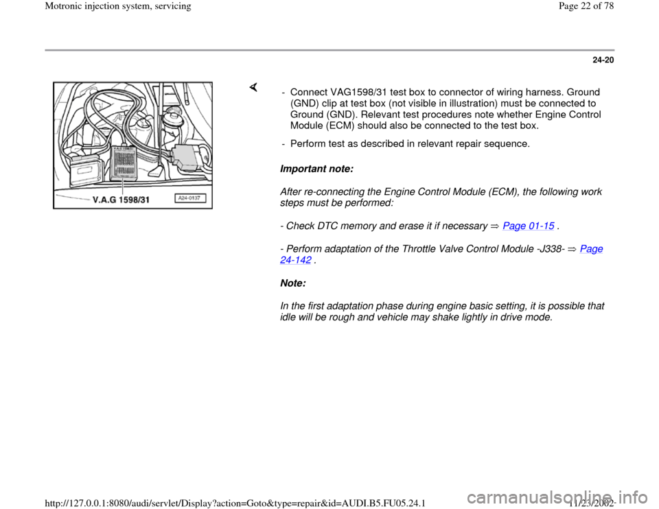
idle will be rough and vehicle may shake lightly in drive mode. - Connect VAG1598/31 test box to connector of wiring harness. Ground
(GND) clip at test box (not visible in illustration) must be connected to
Ground (GND). Relevant test procedures note whether Engine Control
Module (ECM) should also be connected to the test box.
- Perform test as described in relevant repair sequence.
Pa
ge 22 of 78 Motronic in
jection s
ystem, servicin
g
11/23/2002 htt
p://127.0.0.1:8080/audi/servlet/Dis
play?action=Goto&t
yp
e=re
pair&id=AUDI.B5.FU05.24.1
Page 26 of 78
24-24
- Observe notes for coding new Engine Control
Module (ECM) Page 01
-71
.
- For vehicles with cruise control (discernable at
steering column), switch this free in ECM:
Repair Manual, Electrical Equipment, Repair
Group 01; On Board Diagnostic (OBD) of cruise control system; Cruise control system, checking
- Adapt immobilizer to Engine Control Module
(ECM):
Repair Manual, Electrical Equipment, Repair
Group 01; On Board Diagnostic (OBD) of immobilizer after replacing Engine Control Module (ECM)
- For vehicles with automatic transmission, the
kick down function must be learned Page 24
-
161
.
- Generate readiness code Page 01
-82
.
Note:
In the first adaptation phase during engine basic
setting, it is possible that idle will be rough and
vehicle may shake lightly in drive mode.
Pa
ge 26 of 78 Motronic in
jection s
ystem, servicin
g
11/23/2002 htt
p://127.0.0.1:8080/audi/servlet/Dis
play?action=Goto&t
yp
e=re
pair&id=AUDI.B5.FU05.24.1
Page 45 of 78
24-38
Checking voltage supply
Test requirements:
Fuel Pump (FP) OK, checking Page 24
-
49
.
Fuse for fuel injectors OK
Electrical Wiring Diagrams, Troubleshooting &
Component Locations binder
- Disconnect harness connector at the fuel
injector to be tested.
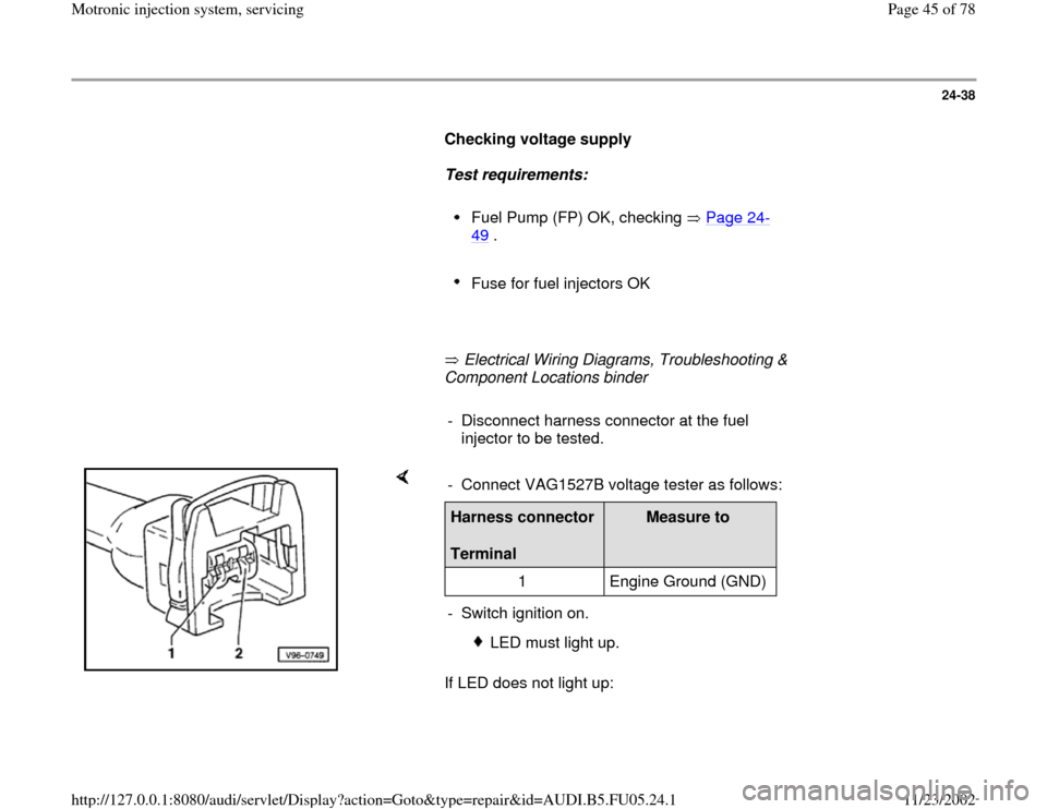
If LED does not light up: - Connect VAG1527B voltage tester as follows:Harness connector
Terminal
Measure to
1 Engine Ground (GND)
- Switch ignition on.
LED must light up.
Pa
ge 45 of 78 Motronic in
jection s
ystem, servicin
g
11/23/2002 htt
p://127.0.0.1:8080/audi/servlet/Dis
play?action=Goto&t
yp
e=re
pair&id=AUDI.B5.FU05.24.1
Page 47 of 78
24-39
- Repair open circuit if necessary.
If LED lights up:
Checking activation
Test requirement:
Internal resistance of valve OK
Note:
Voltage testers do not go out completely during low current pick-up
between activations by the ECM, but rather continue to glow a little and
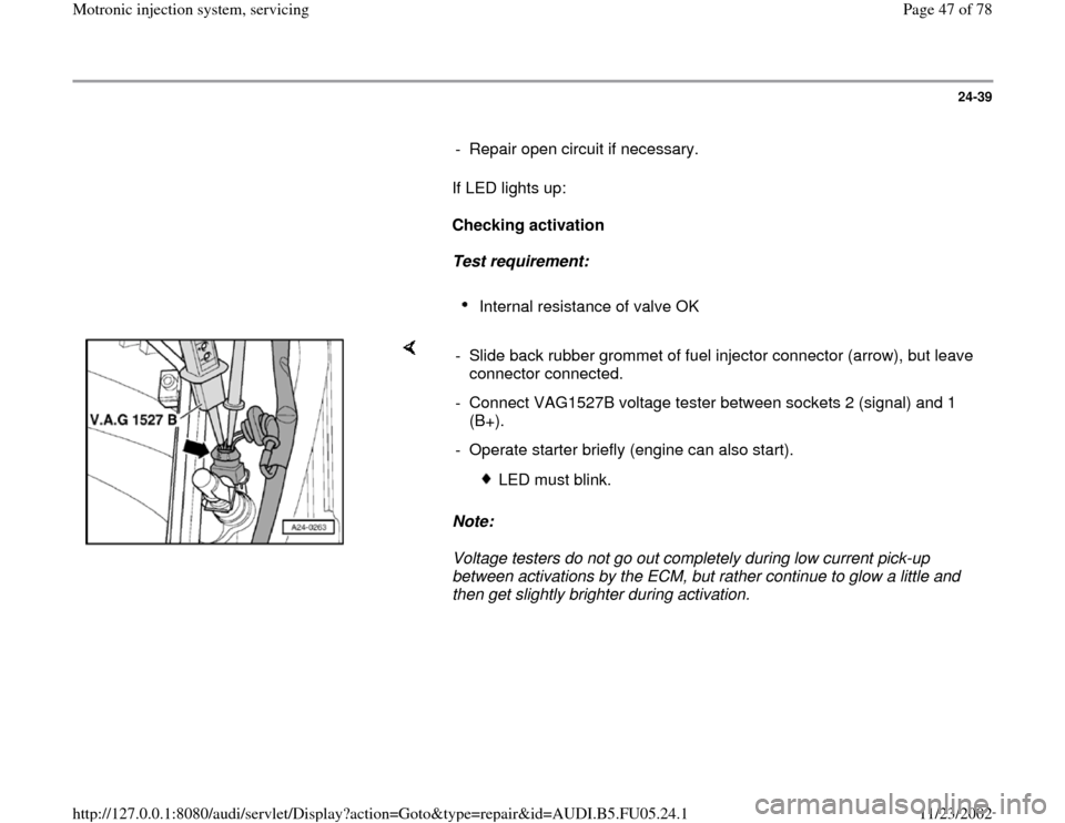
then get slightly brighter during activation. - Slide back rubber grommet of fuel injector connector (arrow), but leave
connector connected.
- Connect VAG1527B voltage tester between sockets 2 (signal) and 1
(B+).
- Operate starter briefly (engine can also start).
LED must blink.
Pa
ge 47 of 78 Motronic in
jection s
ystem, servicin
g
11/23/2002 htt
p://127.0.0.1:8080/audi/servlet/Dis
play?action=Goto&t
yp
e=re
pair&id=AUDI.B5.FU05.24.1
Page 52 of 78
24-44
- Disengage retaining clip and remove fuel
injector.
Note:
Fuel lines must be disconnected before replacing
fuel distributor.
Installation is reverse of removal, noting the
following:
Remove O-rings at all opened connections.
(Never remove plastic cap from valve head
to replace front O-ring - pry O-ring off over
plastic cap).
Lightly lubricate O-rings with clean engine
oil.
Make sure fuel injectors are in place and
seated correctly
Check clip for unobstructed fitting.
Place fuel rail with secured fuel injectors
onto intake manifold, and apply uniform
pressure to press it in.
Tightening torque
Pa
ge 52 of 78 Motronic in
jection s
ystem, servicin
g
11/23/2002 htt
p://127.0.0.1:8080/audi/servlet/Dis
play?action=Goto&t
yp
e=re
pair&id=AUDI.B5.FU05.24.1