check AUDI A6 1996 C5 / 2.G AEB ATW Engines Pistons And Connecting Rods Workshop Manual
[x] Cancel search | Manufacturer: AUDI, Model Year: 1996, Model line: A6, Model: AUDI A6 1996 C5 / 2.GPages: 9, PDF Size: 0.1 MB
Page 2 of 9
13-54
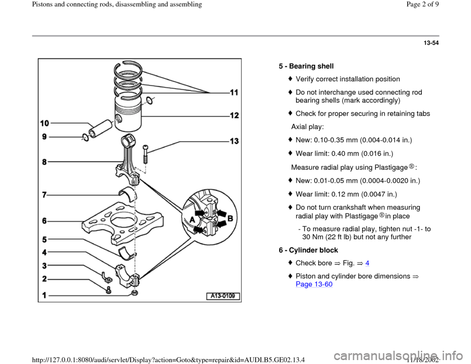
5 -
Bearing shell
Verify correct installation positionDo not interchange used connecting rod
bearing shells (mark accordingly) Check for proper securing in retaining tabs
Axial play:New: 0.10-0.35 mm (0.004-0.014 in.)Wear limit: 0.40 mm (0.016 in.)
Measure radial play using Plastigage :New: 0.01-0.05 mm (0.0004-0.0020 in.)Wear limit: 0.12 mm (0.0047 in.)Do not turn crankshaft when measuring
radial play with Plastigage in place
- To measure radial play, tighten nut -1- to
30 Nm (22 ft lb) but not any further
6 -
Cylinder block
Check bore Fig. 4Piston and cylinder bore dimensions
Page 13
-60
Pa
ge 2 of 9 Pistons and connectin
g rods, disassemblin
g and assemblin
g
11/18/2002 htt
p://127.0.0.1:8080/audi/servlet/Dis
play?action=Goto&t
yp
e=re
pair&id=AUDI.B5.GE02.13.4
Page 4 of 9
13-56
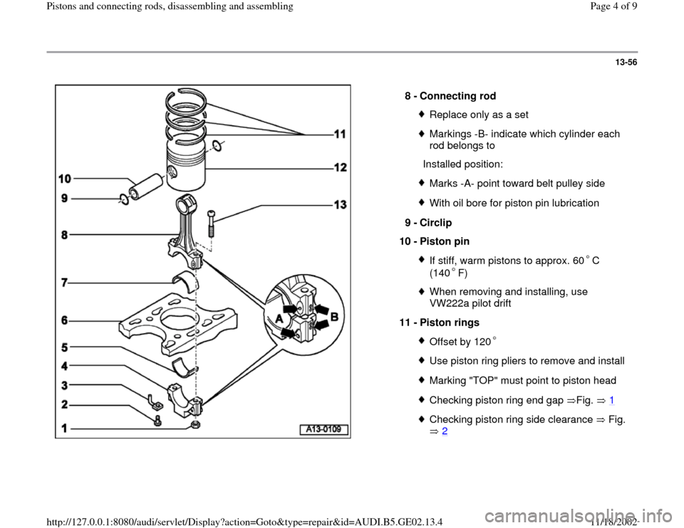
8 -
Connecting rod
Replace only as a setMarkings -B- indicate which cylinder each
rod belongs to
Installed position:Marks -A- point toward belt pulley sideWith oil bore for piston pin lubrication
9 -
Circlip
10 -
Piston pin If stiff, warm pistons to approx. 60 C
(140 F) When removing and installing, use
VW222a pilot drift
11 -
Piston rings Offset by 120Use piston ring pliers to remove and installMarking "TOP" must point to piston headChecking piston ring end gap Fig. 1Checking piston ring side clearance Fig.
2
Pa
ge 4 of 9 Pistons and connectin
g rods, disassemblin
g and assemblin
g
11/18/2002 htt
p://127.0.0.1:8080/audi/servlet/Dis
play?action=Goto&t
yp
e=re
pair&id=AUDI.B5.GE02.13.4
Page 5 of 9
13-57
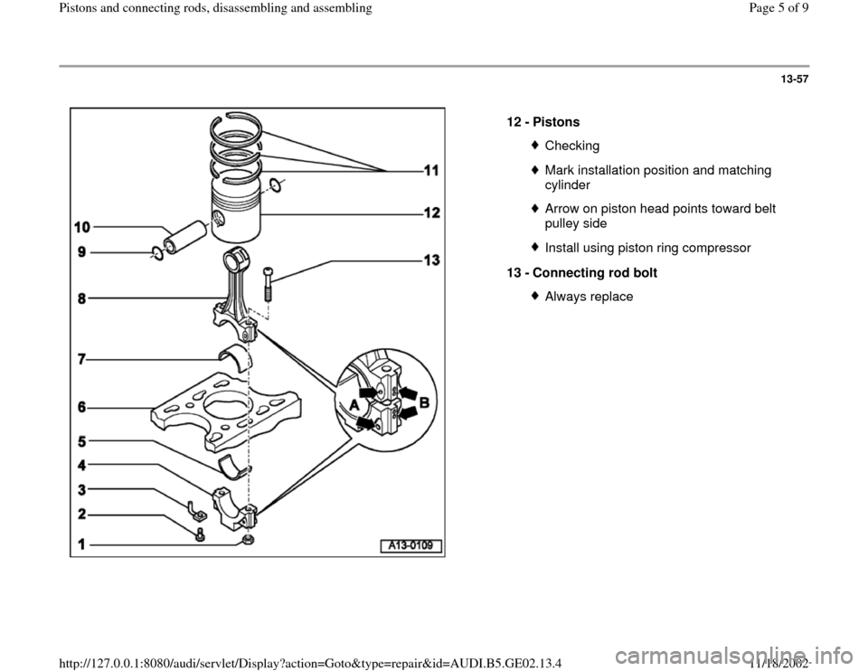
12 -
Pistons
CheckingMark installation position and matching
cylinder Arrow on piston head points toward belt
pulley side Install using piston ring compressor
13 -
Connecting rod bolt Always replace
Pa
ge 5 of 9 Pistons and connectin
g rods, disassemblin
g and assemblin
g
11/18/2002 htt
p://127.0.0.1:8080/audi/servlet/Dis
play?action=Goto&t
yp
e=re
pair&id=AUDI.B5.GE02.13.4
Page 6 of 9
13-58
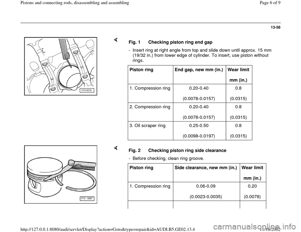
Fig. 1 Checking piston ring end gap
- Insert ring at right angle from top and slide down until approx. 15 mm
(19/32 in.) from lower edge of cylinder. To insert, use piston without
rings. Piston ring
End gap, new mm (in.)
Wear limit
mm (in.)
1. Compression ring 0.20-0.40
(0.0078-0.0157) 0.8
(0.0315)
2. Compression ring 0.20-0.40
(0.0078-0.0157) 0.8
(0.0315)
3. Oil scraper ring 0.25-0.50
(0.0098-0.0197) 0.8
(0.0315)
Fig. 2 Checking piston ring side clearance
- Before checking, clean ring groove.Piston ring
Side clearance, new mm (in.)
Wear limit
mm (in.)
1. Compression ring 0.06-0.09
(0.0023-0.0035) 0.20
(0.0078)
Pa
ge 6 of 9 Pistons and connectin
g rods, disassemblin
g and assemblin
g
11/18/2002 htt
p://127.0.0.1:8080/audi/servlet/Dis
play?action=Goto&t
yp
e=re
pair&id=AUDI.B5.GE02.13.4
Page 8 of 9
13-59
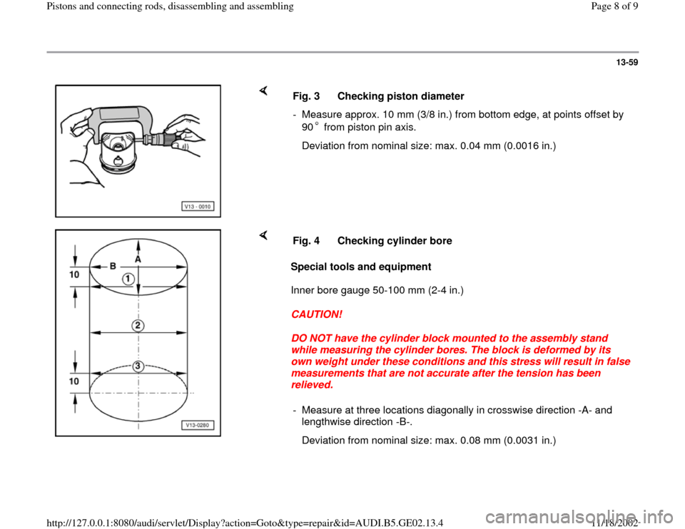
Fig. 3 Checking piston diameter
- Measure approx. 10 mm (3/8 in.) from bottom edge, at points offset by
90 from piston pin axis. Deviation from nominal size: max. 0.04 mm (0.0016 in.)
Special tools and equipment
Inner bore gauge 50-100 mm (2-4 in.)
CAUTION!
DO NOT have the cylinder block mounted to the assembly stand
while measuring the cylinder bores. The block is deformed by its
own weight under these conditions and this stress will result in false
measurements that are not accurate after the tension has been
relieved. Fig. 4 Checking cylinder bore
- Measure at three locations diagonally in crosswise direction -A- and
lengthwise direction -B-.
Deviation from nominal size: max. 0.08 mm (0.0031 in.)
Pa
ge 8 of 9 Pistons and connectin
g rods, disassemblin
g and assemblin
g
11/18/2002 htt
p://127.0.0.1:8080/audi/servlet/Dis
play?action=Goto&t
yp
e=re
pair&id=AUDI.B5.GE02.13.4