differential AUDI A6 1997 C5 / 2.G 01V Transmission Drive Pinion And Ring Gear Adjust Workshop Manual
[x] Cancel search | Manufacturer: AUDI, Model Year: 1997, Model line: A6, Model: AUDI A6 1997 C5 / 2.GPages: 38, PDF Size: 0.52 MB
Page 5 of 38
39-169
Gear set, adjustment sequence
If drive pinion and gear ring have to be adjusted,
the following sequence is recommended for
maximum efficiency:
1.) Determine total shim thickness "Stot"for S1 +
S2 for the specified pre-tension of tapered
roller bearings for differential.
2.) Determine total shim thickness "S3" so that
the drive pinion is installed in the same
location as on the test machine during
production.
3.) Distribute total shim thickness Stotal S1 +
S2, so that the specified backlash between
ring gear and drive pinion is maintained.
Note:
Overview of components and adjustment shims
page 39
-171
.
Pa
ge 5 of 38 Drive
pinion and rin
g gear, ad
justin
g
11/20/2002 htt
p://127.0.0.1:8080/audi/servlet/Dis
play?action=Goto&t
yp
e=re
pair&id=AUDI.B5.AT01.39.15
Page 6 of 38
39-170
Adjustment overview
Note:
When working on transmission, drive pinion or gear set only need to be adjusted if components were replaced which directly
influence the final drive. Note the follow table to prevent unnecessary adjustments:
Component to be adjusted:
Component replaced:
Ring gear
"S1"+"S2"
1)
page 39
-186
Drive pinion
"S3"
1)
via deviation "r"
page 39-177
Backlash
Checking
page 39
-192
Final drive housing X X X
Differential housing X X
Tapered roller bearing for drive pinion X X
Tapered roller bearing for differential X X
Gear set
2)
X X X
Cover for final drive X X
1) Adjustment shims; Installed position page 39
-171
2) Drive pinion and ring gear; only replace together as a set
Pa
ge 6 of 38 Drive
pinion and rin
g gear, ad
justin
g
11/20/2002 htt
p://127.0.0.1:8080/audi/servlet/Dis
play?action=Goto&t
yp
e=re
pair&id=AUDI.B5.AT01.39.15
Page 7 of 38
39-171
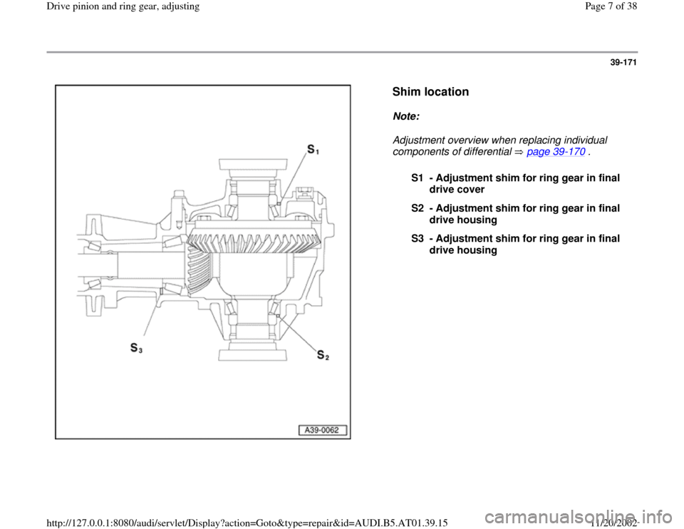
Shim location
Note:
Adjustment overview when replacing individual
components of differential page 39
-170
.
S1 - Adjustment shim for ring gear in final
drive cover
S2 - Adjustment shim for ring gear in final
drive housing
S3 - Adjustment shim for ring gear in final
drive housing
Pa
ge 7 of 38 Drive
pinion and rin
g gear, ad
justin
g
11/20/2002 htt
p://127.0.0.1:8080/audi/servlet/Dis
play?action=Goto&t
yp
e=re
pair&id=AUDI.B5.AT01.39.15
Page 18 of 38
39-181
Note:
Turn differential at least 5 rotations in each
direction to seat the tapered roller bearings.
Otherwise, measurement will result in false
readings.
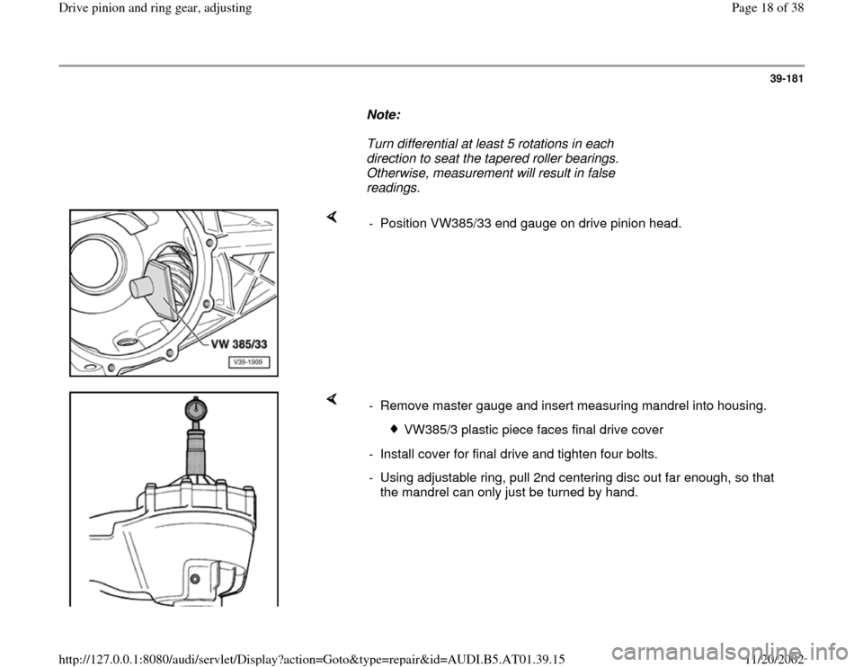
- Position VW385/33 end gauge on drive pinion head.
- Remove master gauge and insert measuring mandrel into housing.
VW385/3 plastic piece faces final drive cover
- Install cover for final drive and tighten four bolts.
- Using adjustable ring, pull 2nd centering disc out far enough, so that
the mandrel can only just be turned by hand.
Pa
ge 18 of 38 Drive
pinion and rin
g gear, ad
justin
g
11/20/2002 htt
p://127.0.0.1:8080/audi/servlet/Dis
play?action=Goto&t
yp
e=re
pair&id=AUDI.B5.AT01.39.15
Page 24 of 38
39-186
Ring gear, adjusting
(Adjusting differential)
Procedures after which the ring gear must be
adjusted Adjustment overview page 39
-
170
.
Notes:
Tapered roller bearings for differential are low-
friction bearings. Therefore friction torque can
only be used for check measurement in a
limited way. A correct adjustment is only
possible by determining the total thickness
"Sges".
Do not grease new tapered roller bearings
additionally for friction torque measurement.
The bearings are already greased with a
special oil from the factory.
Total shim thickness "Stotal" for adjustment
shims "S1" + "S2", determining
(adjust preload of tapered roller bearing for
differential)
Drive pinion removed or ring gear detached
from differential housing
Pa
ge 24 of 38 Drive
pinion and rin
g gear, ad
justin
g
11/20/2002 htt
p://127.0.0.1:8080/audi/servlet/Dis
play?action=Goto&t
yp
e=re
pair&id=AUDI.B5.AT01.39.15
Page 25 of 38
- Pry out drive flange seal using tire iron.
- Remove tapered roller bearings for differential
and remove adjustment shims page 39
-136
.
Pa
ge 25 of 38 Drive
pinion and rin
g gear, ad
justin
g
11/20/2002 htt
p://127.0.0.1:8080/audi/servlet/Dis
play?action=Goto&t
yp
e=re
pair&id=AUDI.B5.AT01.39.15
Page 26 of 38
39-187
- Press tapered roller bearing outer race for left
side of differential housing (housing side)
together with shim "S2" into differential housing
Page 39
-144
. Use a shim "S2*" with a 1.00
mm thickness for measurement purposes (1
shims with 0.80 and 1 with 0.20 mm).
Note:
All measurements are performed with shim S2
with 1.00 mm thickness. The shim will be
indicated by "S2*" in the following procedures.
After determining backlash, S2* is replaced by
final shim S2.
- Press in tapered roller bearing outer race for
right side (cover side) of differential without
adjustment shims to stop Fig. 8
, page 39
-
136
.
- Insert differential in housing. Ring gear is on the
right side (cover side).
- Install cover and tighten bolts to 25 Nm.
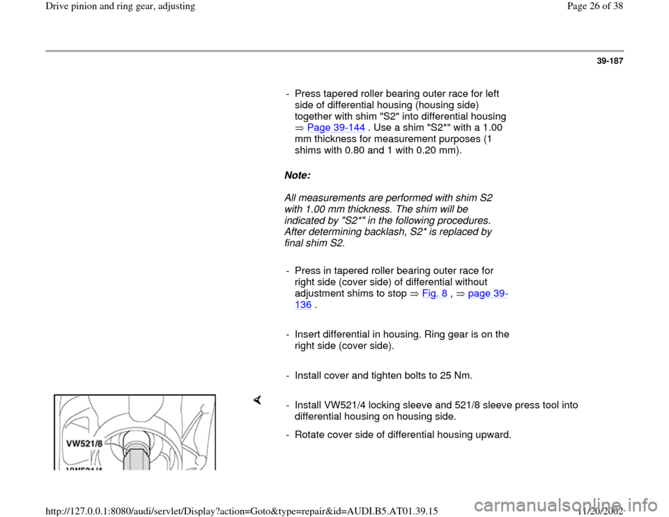
- Install VW521/4 locking sleeve and 521/8 sleeve press tool into
differential housing on housing side.
- Rotate cover side of differential housing upward.
Pa
ge 26 of 38 Drive
pinion and rin
g gear, ad
justin
g
11/20/2002 htt
p://127.0.0.1:8080/audi/servlet/Dis
play?action=Goto&t
yp
e=re
pair&id=AUDI.B5.AT01.39.15
Page 27 of 38
39-188
- Turn differential 5 rotations in each direction to
seat the tapered roller bearing.
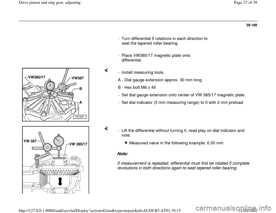
- Place VW385/17 magnetic plate onto
differential.
- Install measuring tools.
A - Dial gauge extension approx. 30 mm long
B - Hex bolt M8 x 45
- Set dial gauge extension onto center of VW 385/17 magnetic plate.
- Set dial indicator (3 mm measuring range) to 0 with 2 mm preload.
Note:
If measurement is repeated, differential must first be rotated 5 complete
revolutions in both directions again to seat tapered roller bearing. - Lift the differential without turning it, read play on dial indicator and
note.
Measured value in the following example: 0.50 mm
Pa
ge 27 of 38 Drive
pinion and rin
g gear, ad
justin
g
11/20/2002 htt
p://127.0.0.1:8080/audi/servlet/Dis
play?action=Goto&t
yp
e=re
pair&id=AUDI.B5.AT01.39.15
Page 30 of 38
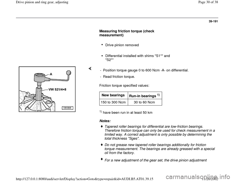
39-191
Measuring friction torque (check
measurement)
Drive pinion removed
Differential installed with shims "S1*" and
"S2*"
Friction torque specified values: 1) have been run in at least 50 km
Notes: - Position torque gauge 0 to 600 Ncm -A- on differential.
- Read friction torque.New bearings
Run-in bearings
1)
150 to 300 Ncm 30 to 60 Ncm
Tapered roller bearings for differential are low-friction bearings.
Therefore friction torque can only be used for check measurement in a
limited way. A correct adjustment is only possible by determining the
total thickness "Sges". Do not grease new tapered roller bearings additionally for friction
torque measurement. The bearings are already greased with a special
oil from the factory. For a new adjustment of the gear set, the drive pinion adjustment
Pa
ge 30 of 38 Drive
pinion and rin
g gear, ad
justin
g
11/20/2002 htt
p://127.0.0.1:8080/audi/servlet/Dis
play?action=Goto&t
yp
e=re
pair&id=AUDI.B5.AT01.39.15
Page 32 of 38
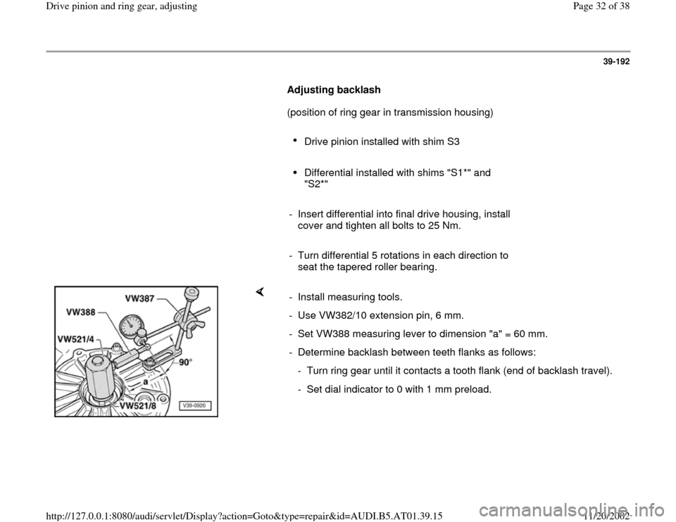
39-192
Adjusting backlash
(position of ring gear in transmission housing)
Drive pinion installed with shim S3
Differential installed with shims "S1*" and
"S2*"
- Insert differential into final drive housing, install
cover and tighten all bolts to 25 Nm.
- Turn differential 5 rotations in each direction to
seat the tapered roller bearing.
- Install measuring tools.
- Use VW382/10 extension pin, 6 mm.
- Set VW388 measuring lever to dimension "a" = 60 mm.
- Determine backlash between teeth flanks as follows:
- Turn ring gear until it contacts a tooth flank (end of backlash travel).
- Set dial indicator to 0 with 1 mm preload.
Pa
ge 32 of 38 Drive
pinion and rin
g gear, ad
justin
g
11/20/2002 htt
p://127.0.0.1:8080/audi/servlet/Dis
play?action=Goto&t
yp
e=re
pair&id=AUDI.B5.AT01.39.15