diagram AUDI A6 1997 C5 / 2.G ATQ Engine Additional Signals Testing Workshop Manual
[x] Cancel search | Manufacturer: AUDI, Model Year: 1997, Model line: A6, Model: AUDI A6 1997 C5 / 2.GPages: 44, PDF Size: 0.19 MB
Page 2 of 44
24-166
Engine speed signal, checking
Note:
The engine speed signal is output at terminal 37
of the Engine Control Module (ECM). The signal
is used, among other things, for RPM display in
the instrument cluster.
- Connect VAG1598/31 test box at wiring harness
to ECM, do not connect ECM Page 24
-17
.
- Check the following wire connection for open
circuit and short circuit to Ground (GND) and B+:
Test box
VAG1598/31
Socket
Instrument cluster
Terminal
37 Electrical Wiring Diagrams,
Troubleshooting & Component
Locations binder
- Repair open circuit or short circuit if
necessary.
Pa
ge 2 of 44 Additional si
gnals, testin
g
11/23/2002 htt
p://127.0.0.1:8080/audi/servlet/Dis
play?action=Goto&t
yp
e=re
pair&id=AUDI.B5.FU05.24.6
Page 3 of 44
24-167
Consumption signal for on board
computer, checking
Notes:
The consumption signal is calculated by the
ECM from the injection time and directed to the
on board computer via terminal 81 of the ECM.
Consumption signal, checking
Electrical Wiring Diagrams, Troubleshooting &
Component Locations binder
Pa
ge 3 of 44 Additional si
gnals, testin
g
11/23/2002 htt
p://127.0.0.1:8080/audi/servlet/Dis
play?action=Goto&t
yp
e=re
pair&id=AUDI.B5.FU05.24.6
Page 4 of 44
24-168
Vehicle speed signal, checking
Notes:
The vehicle speed signal is generated by the
Vehicle Speed Sensor (VSS) -G68- (at
transmission) and processed in the instrument
cluster.
The processed signal enters at terminal 54 of
the ECM and is used for idle stabilization and
tip-in shock reduction during shifting.
Test requirement:
Function and display of speedometer OK.
Troubleshooting:
Electrical Wiring Diagrams, Troubleshooting &
Component Locations binder
Pa
ge 4 of 44 Additional si
gnals, testin
g
11/23/2002 htt
p://127.0.0.1:8080/audi/servlet/Dis
play?action=Goto&t
yp
e=re
pair&id=AUDI.B5.FU05.24.6
Page 6 of 44
24-170
- Connect VAG1598/31 test box at wiring harness
to ECM, do not connect ECM Page 24
-17
.
- Connect VAG1527B voltage tester to sockets 3
(B+) and 54 (VSS) of VAG1598/31 test box.
- Switch ignition on and turn front left wheel by
hand.
LED must blink (very brief blink signal).
If LED does not blink:
- Check the following wire connection for open
circuit and short circuit to Ground (GND) and B+:
Test box
VAG1598/31
Socket
Instrument cluster
Terminal
54 Electrical Wiring Diagrams,
Troubleshooting & Component
Locations binder
- Repair open circuit or short circuit if
necessary.
Pa
ge 6 of 44 Additional si
gnals, testin
g
11/23/2002 htt
p://127.0.0.1:8080/audi/servlet/Dis
play?action=Goto&t
yp
e=re
pair&id=AUDI.B5.FU05.24.6
Page 7 of 44
24-171
Wire for fuel level signal, checking
Notes:
The Engine Control Module (ECM) receives the
fuel level signal from the instrument cluster.
The processed signal enters at terminal 30 of
the ECM and is used to determine the cause of
certain recognized malfunctions (e.g.
combustion misfires).
- Connect VAG1598/31 test box at wiring harness
to ECM, do not connect ECM Page 24
-17
.
- Check the following wire connection for open
circuit and short circuit to Ground (GND) and B+:
Test box
VAG1598/31
Socket
Instrument cluster
Terminal
30 Electrical Wiring Diagrams,
Troubleshooting & Component
Locations binder
- Repair open circuit or short circuit if
necessary.
Pa
ge 7 of 44 Additional si
gnals, testin
g
11/23/2002 htt
p://127.0.0.1:8080/audi/servlet/Dis
play?action=Goto&t
yp
e=re
pair&id=AUDI.B5.FU05.24.6
Page 11 of 44
24-174
- Depress gas pedal completely (swiftly) and then
release it (brief acceleration).
Specified value in display field 4: Indication
jumps for a few seconds from "Compr. ON"
to "Compr. OFF" (compressor is switched off
when vehicle accelerates).
If indications do not resemble description:
- Connect VAG1598/31 test box at wiring harness
to ECM, do not connect ECM Page 24
-17
.
- Check the following wire connection for open
circuit and short circuit to Ground (GND) and B+:
Test box
VAG1598/31
Socket
A/C control
head -E87-
Terminal
41 Electrical Wiring Diagrams,
Troubleshooting & Component
Locations binder
- Repair open circuit or short circuit if
necessary.
Pa
ge 11 of 44 Additional si
gnals, testin
g
11/23/2002 htt
p://127.0.0.1:8080/audi/servlet/Dis
play?action=Goto&t
yp
e=re
pair&id=AUDI.B5.FU05.24.6
Page 15 of 44
24-177
- Check the following wire connection for open
circuit and short circuit to Ground (GND) and B+:
Test box
VAG1598/31
Socket
A/C control
head -E87-
Terminal
40 Electrical Wiring Diagrams,
Troubleshooting & Component
Locations binder
- Repair open circuit or short circuit if
necessary.
- If there are no malfunctions in the wiring, check
function of A/C system.
Repair Manual, Heating & Air Conditioning,
Repair Group 01
Pa
ge 15 of 44 Additional si
gnals, testin
g
11/23/2002 htt
p://127.0.0.1:8080/audi/servlet/Dis
play?action=Goto&t
yp
e=re
pair&id=AUDI.B5.FU05.24.6
Page 22 of 44
24-182
If LED does not light up:
- Check wire connection from terminal 1 or 3 of
connector for open circuit and short circuit to
Ground (GND):
Electrical Wiring Diagrams, Troubleshooting &
Component Locations binder
- Repair open circuit or short circuit if
necessary.
If LED lights up:
Checking activation
- Connect VAG1598/31 test box at wiring harness
to ECM, do not connect ECM Page 24
-17
.
- Check the following wire connections for open
circuit and short circuit to Ground (GND) and B+:
Harness connector
Terminal
VAG1598/31 test box
Socket
2 56
4 55
Pa
ge 22 of 44 Additional si
gnals, testin
g
11/23/2002 htt
p://127.0.0.1:8080/audi/servlet/Dis
play?action=Goto&t
yp
e=re
pair&id=AUDI.B5.FU05.24.6
Page 29 of 44
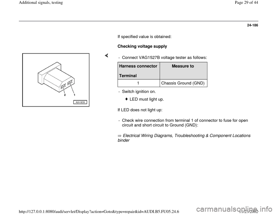
24-186
If specified value is obtained:
Checking voltage supply
If LED does not light up:
Electrical Wiring Diagrams, Troubleshooting & Component Locations
binder - Connect VAG1527B voltage tester as follows:Harness connector
Terminal
Measure to
1 Chassis Ground (GND)
- Switch ignition on.
LED must light up.
- Check wire connection from terminal 1 of connector to fuse for open
circuit and short circuit to Ground (GND):
Pa
ge 29 of 44 Additional si
gnals, testin
g
11/23/2002 htt
p://127.0.0.1:8080/audi/servlet/Dis
play?action=Goto&t
yp
e=re
pair&id=AUDI.B5.FU05.24.6
Page 31 of 44
24-188
Wire for crash signal, checking
The Engine Control Module (ECM) receives the
crash signal ("Crash shut-off was triggered") from
the airbag control module.
When the airbag control module sends the crash
signal to the ECM (during an accident or when
output DTM is being performed for the airbag
system), the ECM switches the Fuel Pump (FP)
off. This means that the engine will stop running
but can be started again afterward (e.g. to
remove vehicle from danger).
- Connect VAG1598/31 test box at wiring harness
to ECM, do not connect ECM Page 24
-17
- Check the following wire connection for open
circuit and short circuit to Ground (GND) and B+:
Test box
VAG1598/31
Socket
Control module for
Airbag -J234-
Terminal
67 Electrical Wiring Diagrams,
Troubleshooting & Component
Locations binder
Pa
ge 31 of 44 Additional si
gnals, testin
g
11/23/2002 htt
p://127.0.0.1:8080/audi/servlet/Dis
play?action=Goto&t
yp
e=re
pair&id=AUDI.B5.FU05.24.6