transmission AUDI A6 1997 C5 / 2.G ATW Engine Motronic Fuel Injection Syst
[x] Cancel search | Manufacturer: AUDI, Model Year: 1997, Model line: A6, Model: AUDI A6 1997 C5 / 2.GPages: 81, PDF Size: 1.03 MB
Page 22 of 81
24-21
Note:
Important note:
After re-connecting the Engine Control Module
(ECM), the following work steps must be
performed:
- Perform adaptation of the Throttle Valve Control
Module -J338- Page 24
-121
.
- For vehicles with automatic transmission, the
kick down function must be adapted Page 24
-
139
.
- Check DTC memory and erase it if necessary
Page 01
-16
.
- If DTC memory was erased, readiness code
must be re-generated Page 01
-73
.
Note:
During the first adaptation phase, it is possible
that idle will be rough and vehicle may shake
lightly in drive mode.
Pa
ge 22 of 81 Motronic fuel in
jection s
ystem, servicin
g
11/21/2002 htt
p://127.0.0.1:8080/audi/servlet/Dis
play?action=Goto&t
yp
e=re
pair&id=AUDI.B5.FU06.24.1
Page 23 of 81
24-22
Procedure following interruption of
voltage supply
Note:
Important note:
After re-connecting voltage supply, the following
work steps must be performed:
- Perform adaptation of the Throttle Valve Control
Module -J338- Page 24
-121
.
- For vehicles with automatic transmission, the
kick down function must be adapted Page 24
-
139
.
- Check DTC memory and erase it if necessary
Page 01
-16
.
- If DTC memory was erased, readiness code
must be re-generated Page 01
-73
.
Note:
During the first adaptation phase, it is possible
that idle will be rough and vehicle may shake
lightly in drive mode.
Pa
ge 23 of 81 Motronic fuel in
jection s
ystem, servicin
g
11/21/2002 htt
p://127.0.0.1:8080/audi/servlet/Dis
play?action=Goto&t
yp
e=re
pair&id=AUDI.B5.FU06.24.1
Page 27 of 81
24-26
Installing
Installation is reverse of removal, noting the
following:
Note:
Important note:
After installing new Engine Control Module
(ECM), the following work steps must be
performed:
- Check DTC memory and erase it if necessary
Page 01
-16
.
- Perform adaptation of the Throttle Valve Control
Module -J338- Page 24
-121
.
- Observe notes for coding new Engine Control
Module (ECM) Page 01
-62
.
- For vehicles with cruise control (discernable at
steering column), switch this free in ECM:
Repair Manual, Electrical Equipment On
Board Diagnostic (OBD), Repair Group 01; OBD for cruise control system
- For vehicles with automatic transmission, the
kick down function must be adapted Page 24
-
Pa
ge 27 of 81 Motronic fuel in
jection s
ystem, servicin
g
11/21/2002 htt
p://127.0.0.1:8080/audi/servlet/Dis
play?action=Goto&t
yp
e=re
pair&id=AUDI.B5.FU06.24.1
Page 30 of 81
24-28
Idle speed (RPM), checking
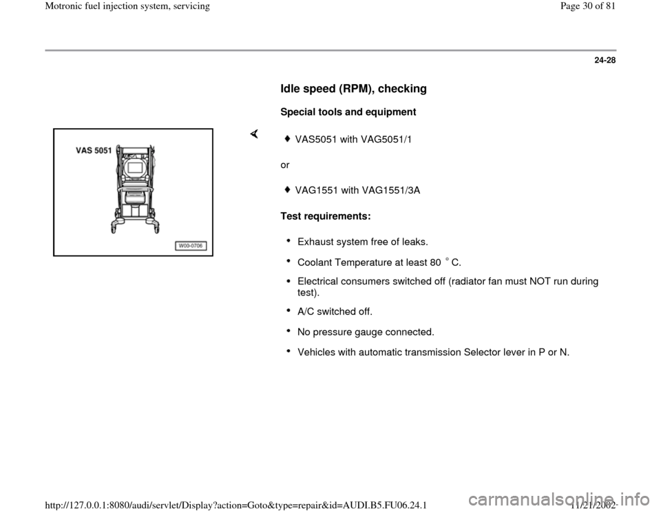
Special tools and equipment
or
Test requirements:
VAS5051 with VAG5051/1VAG1551 with VAG1551/3AExhaust system free of leaks. Coolant Temperature at least 80 C. Electrical consumers switched off (radiator fan must NOT run during
test). A/C switched off. No pressure gauge connected. Vehicles with automatic transmission Selector lever in P or N.
Pa
ge 30 of 81 Motronic fuel in
jection s
ystem, servicin
g
11/21/2002 htt
p://127.0.0.1:8080/audi/servlet/Dis
play?action=Goto&t
yp
e=re
pair&id=AUDI.B5.FU06.24.1
Page 36 of 81
24-32
If idle speed is too high or low and there are
no DTCs in DTC memory, the following tests
(marked with dots) must be performed:
Check for false air in intake air system
Page 24
-68
.
Check throttle valve control module Page 24
-120
.
Evaporative Emission (EVAP) canister purge
regulator valve always open, checking
Page 24
-107
.
Perform adaptation of throttle valve control
module Page 24
-121
.
Significance of 5 digit indication of display group 056 x
x
x
x
x
Display field 4
0 A/C compressor: 0 = A/C compressor off; 1 = A/C compressor on
0 Manual transmission: Indication always 0
Driving mode for automatic transmission: 0 = selector lever in P or N; 1 = selector lever in 2/3/4/D/R
0 Indication always 0
0 Indication always 0
0 Indication always 0
Pa
ge 36 of 81 Motronic fuel in
jection s
ystem, servicin
g
11/21/2002 htt
p://127.0.0.1:8080/audi/servlet/Dis
play?action=Goto&t
yp
e=re
pair&id=AUDI.B5.FU06.24.1
Page 37 of 81
24-33
System pressure, fuel pressure
regulator and residual pressure,
checking
Note:
Fuel pressure regulator regulates fuel pressure
according to intake manifold pressure. This
ensures that the pressure drop at the fuel
injectors remains the same for each speed and
load range of the engine.
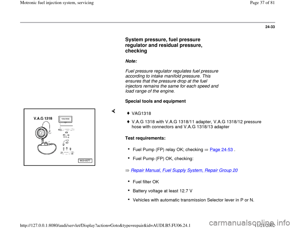
Special tools and equipment
Test requirements:
Repair Manual, Fuel Supply System, Repair Group 20
VAG1318V.A.G 1318 with V.A.G 1318/11 adapter, V.A.G 1318/12 pressure
hose with connectors and V.A.G 1318/13 adapter Fuel Pump (FP) relay OK; checking Page 24
-53
.
Fuel Pump (FP) OK, checking: Fuel filter OK Battery voltage at least 12.7 V Vehicles with automatic transmission Selector lever in P or N.
Pa
ge 37 of 81 Motronic fuel in
jection s
ystem, servicin
g
11/21/2002 htt
p://127.0.0.1:8080/audi/servlet/Dis
play?action=Goto&t
yp
e=re
pair&id=AUDI.B5.FU06.24.1