AUDI A6 1998 C5 / 2.G 01V Transmission Drive Pinion Assembly Workshop Manual
A6 1998 C5 / 2.G
AUDI
AUDI
https://www.carmanualsonline.info/img/6/1192/w960_1192-0.png
AUDI A6 1998 C5 / 2.G 01V Transmission Drive Pinion Assembly Workshop Manual
Page 4 of 14
39-155
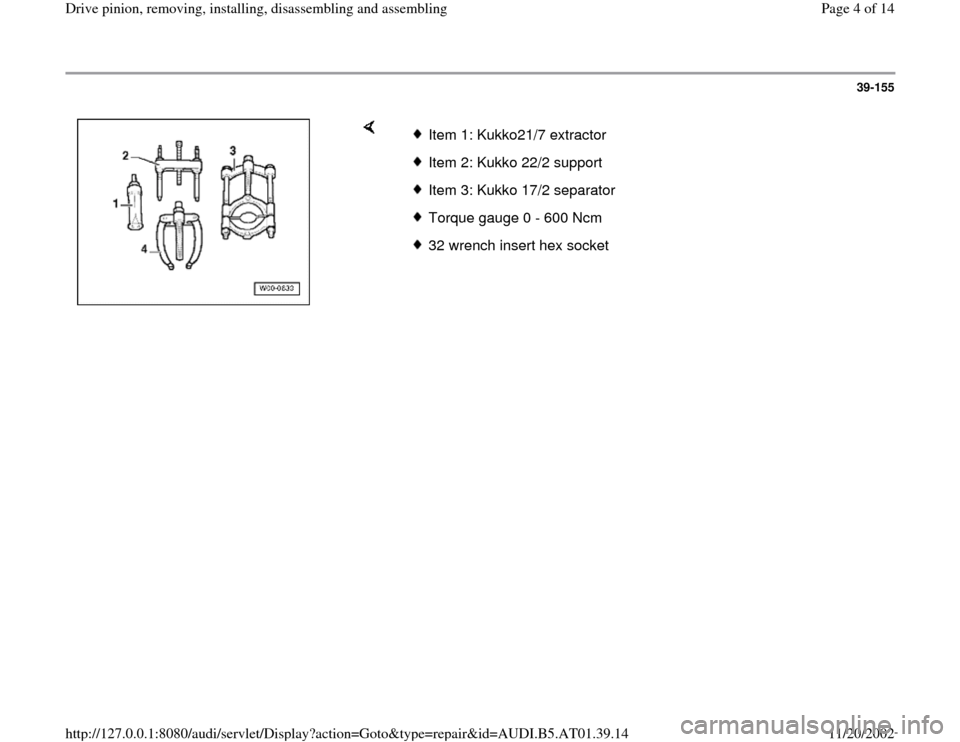
Item 1: Kukko21/7 extractorItem 2: Kukko 22/2 supportItem 3: Kukko 17/2 separatorTorque gauge 0 - 600 Ncm32 wrench insert hex socket
Pa
ge 4 of 14 Drive
pinion, removin
g, installin
g, disassemblin
g and assemblin
g
11/20/2002 htt
p://127.0.0.1:8080/audi/servlet/Dis
play?action=Goto&t
yp
e=re
pair&id=AUDI.B5.AT01.39.14
Page 5 of 14
39-156
Notes:
General repair notes page 00
-27
.
Disconnect torque tube from rear final drive with
the final drive installed page 39
-96
.
Disconnect torque tube from rear final drive with
the final drive removed page 39
-126
.
Replace both tapered roller bearings together. If
possible, use same manufacturer!
Do not grease new tapered roller bearings
additionally for friction torque measurement.
The bearings are already greased with a
special oil from the factory.
Removing differential page 39
-128
.
Adjustments are required when replacing
components marked with
1) Adjustment
overview page 39
-170
.
Pa
ge 5 of 14 Drive
pinion, removin
g, installin
g, disassemblin
g and assemblin
g
11/20/2002 htt
p://127.0.0.1:8080/audi/servlet/Dis
play?action=Goto&t
yp
e=re
pair&id=AUDI.B5.AT01.39.14
Page 6 of 14
39-157
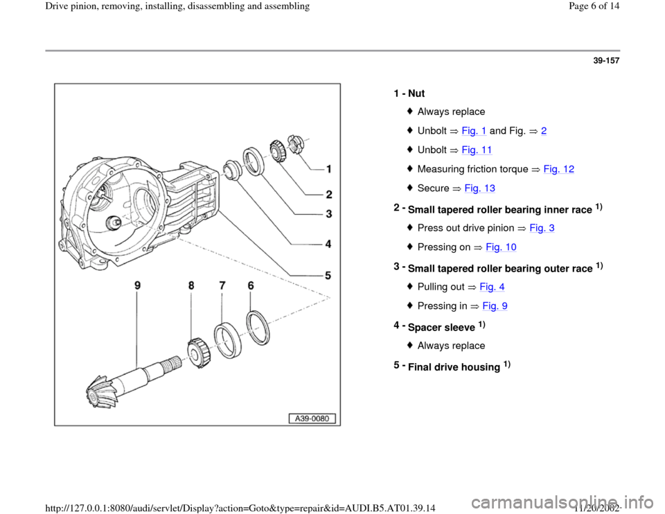
1 -
Nut
Always replaceUnbolt Fig. 1
and Fig. 2
Unbolt Fig. 11Measuring friction torque Fig. 12Secure Fig. 13
2 -
Small tapered roller bearing inner race
1)
Press out drive pinion Fig. 3Pressing on Fig. 10
3 -
Small tapered roller bearing outer race
1)
Pulling out Fig. 4Pressing in Fig. 9
4 -
Spacer sleeve
1)
Always replace
5 -
Final drive housing
1)
Pa
ge 6 of 14 Drive
pinion, removin
g, installin
g, disassemblin
g and assemblin
g
11/20/2002 htt
p://127.0.0.1:8080/audi/servlet/Dis
play?action=Goto&t
yp
e=re
pair&id=AUDI.B5.AT01.39.14
Page 13 of 14
39-164
Note:
If the specified friction torque is surpassed, replace spacer sleeve and
repeat adjustment! Any spacer sleeve that has been pressed together too
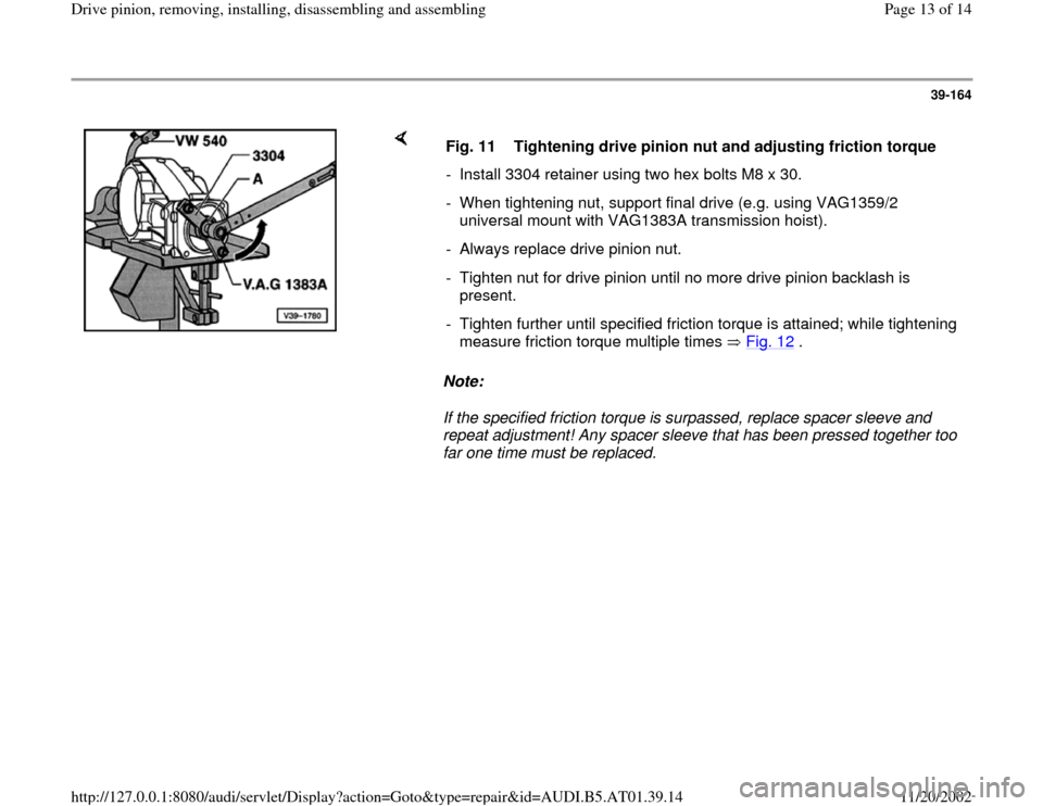
far one time must be replaced. Fig. 11 Tightening drive pinion nut and adjusting friction torque
- Install 3304 retainer using two hex bolts M8 x 30.
- When tightening nut, support final drive (e.g. using VAG1359/2
universal mount with VAG1383A transmission hoist).
- Always replace drive pinion nut.
- Tighten nut for drive pinion until no more drive pinion backlash is
present.
- Tighten further until specified friction torque is attained; while tightening
measure friction torque multiple times Fig. 12
.
Pa
ge 13 of 14 Drive
pinion, removin
g, installin
g, disassemblin
g and assemblin
g
11/20/2002 htt
p://127.0.0.1:8080/audi/servlet/Dis
play?action=Goto&t
yp
e=re
pair&id=AUDI.B5.AT01.39.14
Page 14 of 14
39-165
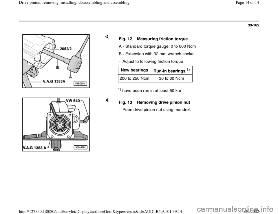
1) have been run in at least 50 km Fig. 12 Measuring friction torque
A - Standard torque gauge, 0 to 600 Ncm
B - Extension with 32 mm wrench socket
- Adjust to following friction torqueNew bearings
Run-in bearings
1)
200 to 250 Ncm 30 to 60 Ncm
Fig. 13 Removing drive pinion nut
- Peen drive pinion nut using mandrel.
Pa
ge 14 of 14 Drive
pinion, removin
g, installin
g, disassemblin
g and assemblin
g
11/20/2002 htt
p://127.0.0.1:8080/audi/servlet/Dis
play?action=Goto&t
yp
e=re
pair&id=AUDI.B5.AT01.39.14
