AUDI A6 1999 C5 / 2.G 01V Transmission Electrical Testing Service Manual
Manufacturer: AUDI, Model Year: 1999,
Model line: A6,
Model: AUDI A6 1999 C5 / 2.G
Pages: 66, PDF Size: 0.28 MB
AUDI A6 1999 C5 / 2.G 01V Transmission Electrical Testing Service Manual
A6 1999 C5 / 2.G
AUDI
AUDI
https://www.carmanualsonline.info/img/6/1218/w960_1218-0.png
AUDI A6 1999 C5 / 2.G 01V Transmission Electrical Testing Service Manual
Trending: check engine light, wheel, change time, fuse box, sensor, battery location, tow
Page 41 of 66
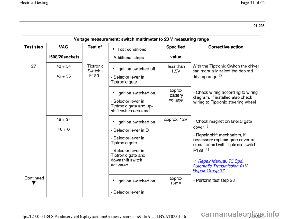
01-298
Voltage measurement: switch multimeter to 20 V measuring range
Test step
VAG
1598/20sockets Test of
Test conditions
- Additional stepsSpecified
value Corrective action
27
46 + 54
46 + 55 Tiptronic
Switch -
F189- Ignition switched off
- Selector lever in
Tiptronic gate less than
1.5V With the Tiptronic Switch the driver
can manually select the desired
driving range
2)
Ignition switched on
- Selector lever in
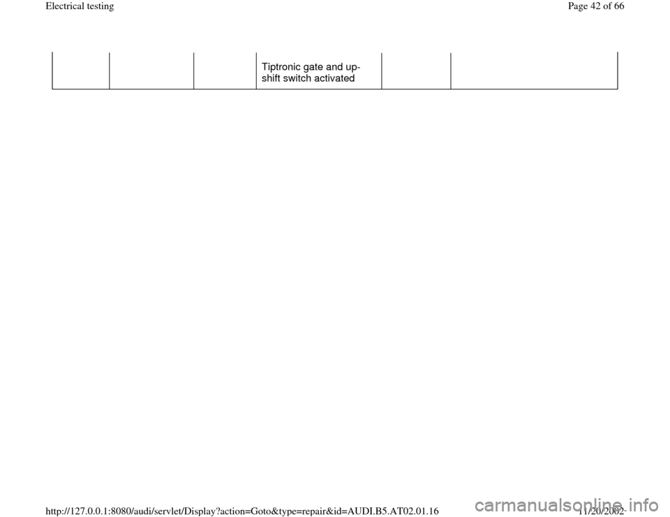
Tiptronic gate and up-
shift switch actuated approx.
battery
voltage - Check wiring according to wiring
diagram. If installed also check
wiring to Tiptronic steering wheel
46 + 34
46 + 6 Ignition switched on
- Selector lever in D
- Selector lever in
Tiptronic gate
- Selector lever in
Tiptronic gate and
downshift switch
activated approx. 12V
Repair Manual, T5 Spd.
Automatic Transmission 01V, Repair Group 37
- Check magnet on lateral gate
cover
1)
- Repair shift mechanism, if
necessary replace gate cover or
circuit board with Tiptronic switch -
F189- 1)
Continued
Ignition switched on
- Selector lever in approx.
15mV - Perform test step 28
Pa
ge 41 of 66 Electrical testin
g
11/20/2002 htt
p://127.0.0.1:8080/audi/servlet/Dis
play?action=Goto&t
yp
e=re
pair&id=AUDI.B5.AT02.01.16
Page 42 of 66
Tiptronic gate and up-
shift switch activated
Pa
ge 42 of 66 Electrical testin
g
11/20/2002 htt
p://127.0.0.1:8080/audi/servlet/Dis
play?action=Goto&t
yp
e=re
pair&id=AUDI.B5.AT02.01.16
Page 43 of 66
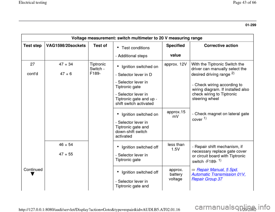
01-299
Voltage measurement: switch multimeter to 20 V measuring range
Test step
VAG1598/20sockets
Test of
Test conditions
- Additional stepsSpecified
value Corrective action
27
cont'd 47 + 34
47 + 6 Tiptronic
Switch -
F189- Ignition switched on
- Selector lever in D
- Selector lever in
Tiptronic gate
- Selector lever in
Tiptronic gate and up -
shift switch activated approx. 12V With the Tiptronic Switch the
driver can manually select the
desired driving range
2)
- Check wiring according to
wiring diagram. If installed also
check wiring to Tiptronic
steering wheel
Ignition switched on
- Selector lever in
Tiptronic gate and
down-shift switch
activated approx.15
mV - Check magnet on lateral gate
cover
1)
46 + 54
47 + 55
Ignition switched off
- Selector lever in
Tiptronic gate less than
1.5V - Repair shift mechanism, if
necessary replace gate cover
or circuit board with Tiptronic
switch -F189-
1)
Continued
Ignition switched off
- Selector lever in
Tiptronic gate and approx.
battery
voltage Repair Manual, 5 Spd.
Automatic Transmission 01V, Repair Group 37
Pa
ge 43 of 66 Electrical testin
g
11/20/2002 htt
p://127.0.0.1:8080/audi/servlet/Dis
play?action=Goto&t
yp
e=re
pair&id=AUDI.B5.AT02.01.16
Page 44 of 66
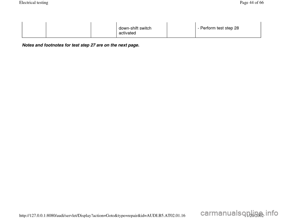
down-shift switch
activated - Perform test step 28
Notes and footnotes for test step 27 are on the next page.
Pa
ge 44 of 66 Electrical testin
g
11/20/2002 htt
p://127.0.0.1:8080/audi/servlet/Dis
play?action=Goto&t
yp
e=re
pair&id=AUDI.B5.AT02.01.16
Page 45 of 66
01-300
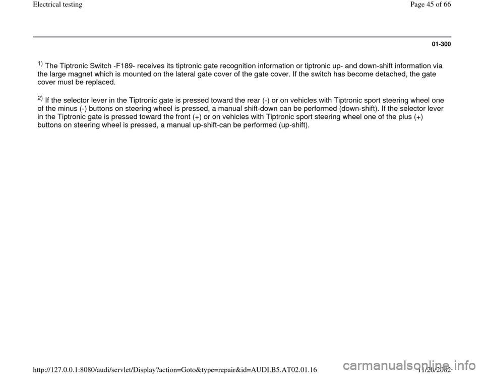
1) The Tiptronic Switch -F189- receives its tiptronic gate recognition information or tiptronic up- and down-shift information via
the large magnet which is mounted on the lateral gate cover of the gate cover. If the switch has become detached, the gate
cover must be replaced. 2) If the selector lever in the Tiptronic gate is pressed toward the rear (-) or on vehicles with Tiptronic sport steering wheel one
of the minus (-) buttons on steering wheel is pressed, a manual shift-down can be performed (down-shift). If the selector lever
in the Tiptronic gate is pressed toward the front (+) or on vehicles with Tiptronic sport steering wheel one of the plus (+)
buttons on steering wheel is pressed, a manual up-shift-can be performed (up-shift).
Pa
ge 45 of 66 Electrical testin
g
11/20/2002 htt
p://127.0.0.1:8080/audi/servlet/Dis
play?action=Goto&t
yp
e=re
pair&id=AUDI.B5.AT02.01.16
Page 46 of 66
01-301
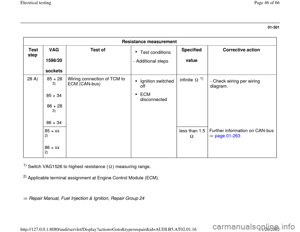
Resistance measurement
Test
step VAG
1598/20
sockets Test of
Test conditions
- Additional stepsSpecified
value Corrective action
28 A) 85 + 28
3)
85 + 34
86 + 28 3)
86 + 34 Wiring connection of TCM to
ECM (CAN-bus)
Ignition switched
off ECM
disconnected infinite
1)
- Check wiring per wiring
diagram.
85 + xx
2)
86 + xx 2)
less than 1.5
Further information on CAN-bus
page 01
-263
1) Switch VAG1526 to highest resistance ( ) measuring range. 2) Applicable terminal assignment at Engine Control Module (ECM).
Repair Manual, Fuel Injection & Ignition, Repair Group 24
Pa
ge 46 of 66 Electrical testin
g
11/20/2002 htt
p://127.0.0.1:8080/audi/servlet/Dis
play?action=Goto&t
yp
e=re
pair&id=AUDI.B5.AT02.01.16
Page 47 of 66
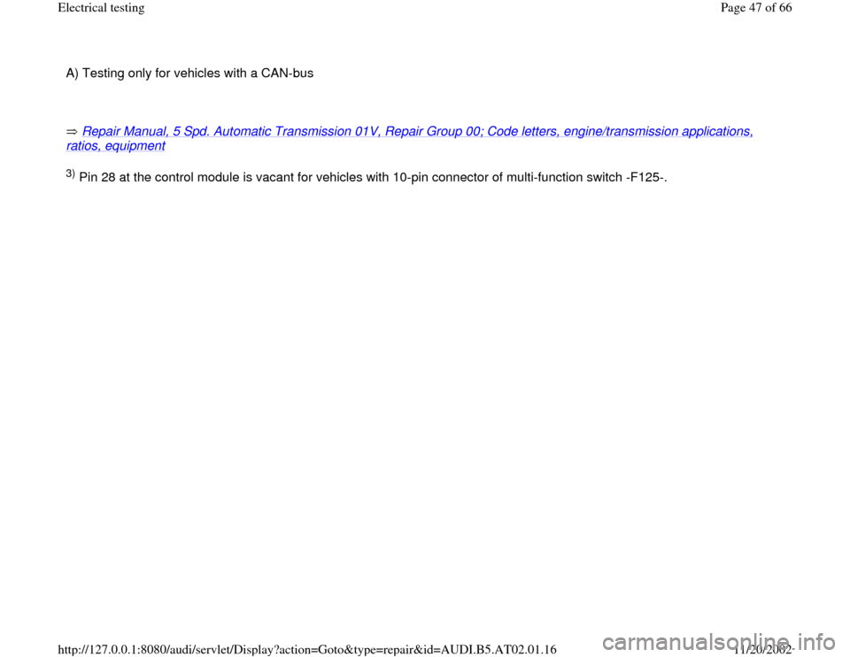
A) Testing only for vehicles with a CAN-bus
Repair Manual, 5 Spd. Automatic Transmission 01V, Repair Group 00; Code letters, engine/transmission applications, ratios, equipment
3) Pin 28 at the control module is vacant for vehicles with 10-pin connector of multi-function switch -F125-.
Pa
ge 47 of 66 Electrical testin
g
11/20/2002 htt
p://127.0.0.1:8080/audi/servlet/Dis
play?action=Goto&t
yp
e=re
pair&id=AUDI.B5.AT02.01.16
Page 48 of 66
01-302
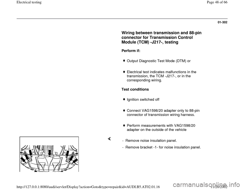
Wiring between transmission and 88-pin
connector for Transmission Control
Module (TCM) -J217-, testing
Perform if:
Output Diagnostic Test Mode (DTM) or
Electrical test indicates malfunctions in the
transmission, the TCM -J217-, or in the
corresponding wiring.
Test conditions
Ignition switched off
Connect VAG1598/20 adapter only to 88-pin
connector of transmission wiring harness.
Perform measurements with VAG1598/20
adapter on the outside of the vehicle
- Remove noise insulation panel.
- Remove bracket -1- for noise insulation panel.
Pa
ge 48 of 66 Electrical testin
g
11/20/2002 htt
p://127.0.0.1:8080/audi/servlet/Dis
play?action=Goto&t
yp
e=re
pair&id=AUDI.B5.AT02.01.16
Page 49 of 66
01-303
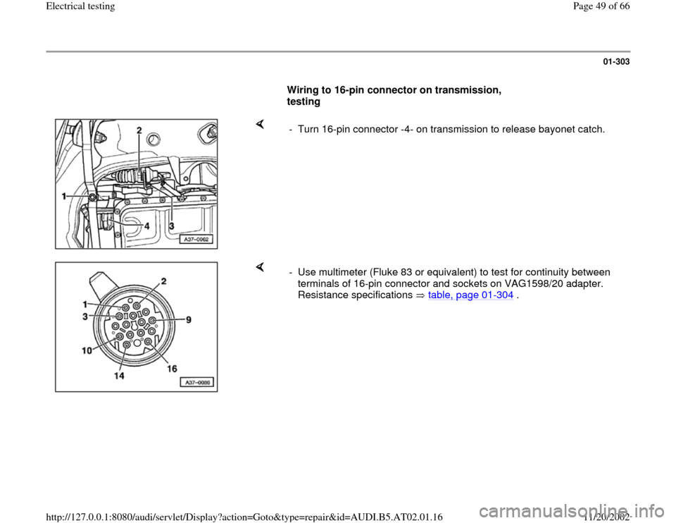
Wiring to 16-pin connector on transmission,
testing
- Turn 16-pin connector -4- on transmission to release bayonet catch.
- Use multimeter (Fluke 83 or equivalent) to test for continuity between
terminals of 16-pin connector and sockets on VAG1598/20 adapter.
Resistance specifications table, page 01
-304
.
Pa
ge 49 of 66 Electrical testin
g
11/20/2002 htt
p://127.0.0.1:8080/audi/servlet/Dis
play?action=Goto&t
yp
e=re
pair&id=AUDI.B5.AT02.01.16
Page 50 of 66
01-304
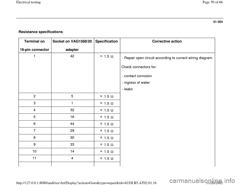
Resistance specifications
Terminal on
16-pin connector Socket on VAG1598/20
adapter Specification
Corrective action
1 42
1.5
Check connectors for: - Repair open circuit according to current wiring diagram.
- contact corrosion
- ingress of water
- leaks
2 5
1.5
3 1
1.5
4 32
1.5
5 16
1.5
6 44
1.5
7 29
1.5
8 30
1.5
9 33
1.5
10 14
1.5
11 4
1.5
Pa
ge 50 of 66 Electrical testin
g
11/20/2002 htt
p://127.0.0.1:8080/audi/servlet/Dis
play?action=Goto&t
yp
e=re
pair&id=AUDI.B5.AT02.01.16
Trending: air condition, fuse box diagram, battery location, wheel, ABS, manual transmission, transmission fluid

