buttons AUDI A6 1999 C5 / 2.G AHA Engine Motronic Ignition System Workshop Manual
[x] Cancel search | Manufacturer: AUDI, Model Year: 1999, Model line: A6, Model: AUDI A6 1999 C5 / 2.GPages: 34, PDF Size: 0.19 MB
Page 9 of 34
28-8
Knock sensor and knock sensor control,
checking
Required special tools and test equipment
VAG1551/1552 Scan Tool (ST) with
VAG1551/3 adapter cable
VAG1598/22 test box
Multimeter US1119 (Fluke 83 or equivalent)
VW1594 connector test kit
Wiring diagrams
Checking
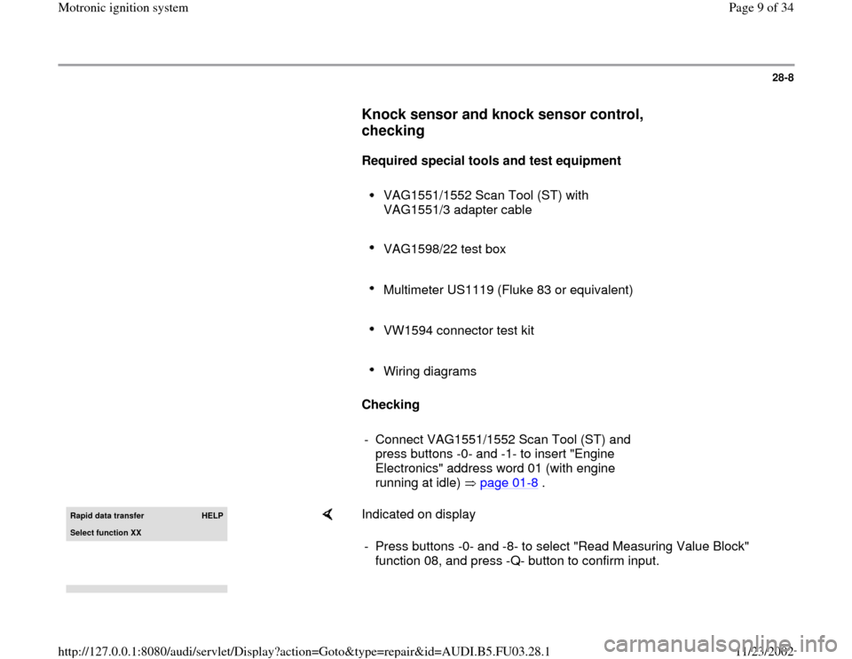
- Connect VAG1551/1552 Scan Tool (ST) and
press buttons -0- and -1- to insert "Engine
Electronics" address word 01 (with engine
running at idle) page 01
-8 .
Rapid data transfer
HELP
Select function XX
Indicated on display
- Press buttons -0- and -8- to select "Read Measuring Value Block"
function 08, and press -Q- button to confirm input.
Pa
ge 9 of 34 Motronic i
gnition s
ystem
11/23/2002 htt
p://127.0.0.1:8080/audi/servlet/Dis
play?action=Goto&t
yp
e=re
pair&id=AUDI.B5.FU03.28.1
Page 11 of 34
28-9
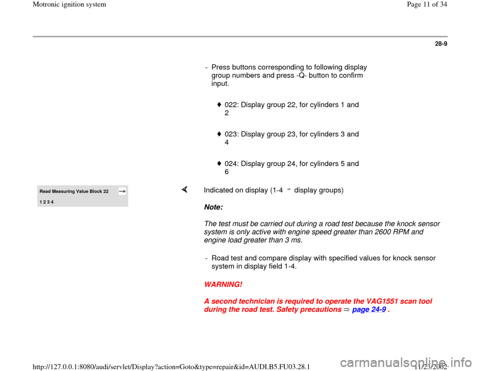
- Press buttons corresponding to following display
group numbers and press -Q- button to confirm
input.
022: Display group 22, for cylinders 1 and
2
023: Display group 23, for cylinders 3 and
4
024: Display group 24, for cylinders 5 and
6
Read Measuring Value Block 22 1 2 3 4
Indicated on display (1-4 display groups)
Note:
The test must be carried out during a road test because the knock sensor
system is only active with engine speed greater than 2600 RPM and
engine load greater than 3 ms.
WARNING!
A second technician is required to operate the VAG1551 scan tool
during the road test. Safety precautions page 24
-9 .
- Road test and compare display with specified values for knock sensor
system in display field 1-4.
Pa
ge 11 of 34 Motronic i
gnition s
ystem
11/23/2002 htt
p://127.0.0.1:8080/audi/servlet/Dis
play?action=Goto&t
yp
e=re
pair&id=AUDI.B5.FU03.28.1
Page 12 of 34
28-10
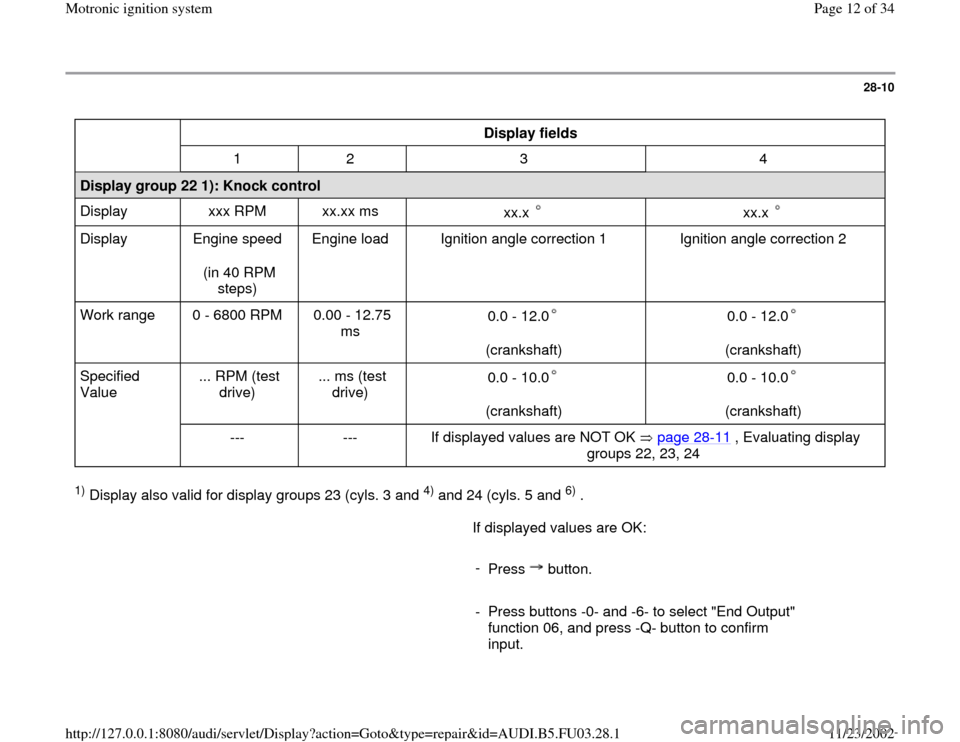
Display fields
1 2 3 4
Display group 22 1): Knock control
Display xxx RPM xx.xx ms
xx.x
xx.x
Display Engine speed
(in 40 RPM
steps) Engine load Ignition angle correction 1 Ignition angle correction 2
Work range 0 - 6800 RPM 0.00 - 12.75
ms 0.0 - 12.0
(crankshaft)
0.0 - 12.0
(crankshaft)
Specified
Value ... RPM (test
drive) ... ms (test
drive) 0.0 - 10.0
(crankshaft)
0.0 - 10.0
(crankshaft)
--- --- If displayed values are NOT OK page 28
-11
, Evaluating display
groups 22, 23, 24
1) Display also valid for display groups 23 (cyls. 3 and
4) and 24 (cyls. 5 and
6) .
If displayed values are OK:
-
Press button.
- Press buttons -0- and -6- to select "End Output"
function 06, and press -Q- button to confirm
input.
Pa
ge 12 of 34 Motronic i
gnition s
ystem
11/23/2002 htt
p://127.0.0.1:8080/audi/servlet/Dis
play?action=Goto&t
yp
e=re
pair&id=AUDI.B5.FU03.28.1
Page 19 of 34
28-16
Misfire recognition, checking
Required special tools and test equipment
VAG1551 or VAG1552 Scan Tool (ST) with
VAG1551/3 adapter cable
Checking
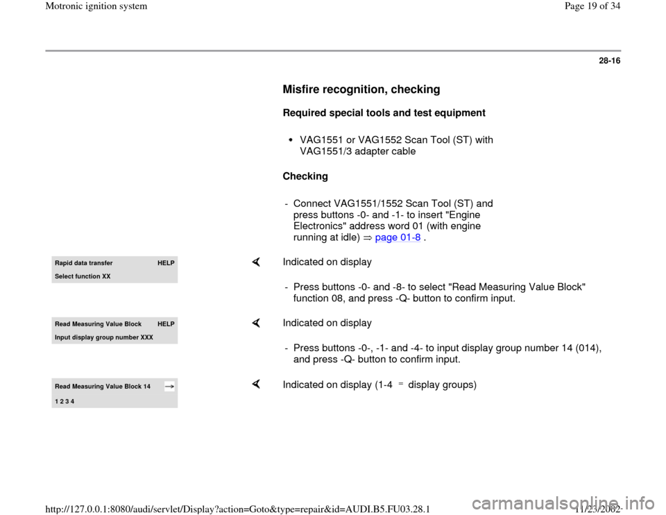
- Connect VAG1551/1552 Scan Tool (ST) and
press buttons -0- and -1- to insert "Engine
Electronics" address word 01 (with engine
running at idle) page 01
-8 .
Rapid data transfer
HELP
Select function XX
Indicated on display
- Press buttons -0- and -8- to select "Read Measuring Value Block"
function 08, and press -Q- button to confirm input.
Read Measuring Value Block
HELP
Input displa
y group number XXX
Indicated on display
- Press buttons -0-, -1- and -4- to input display group number 14 (014),
and press -Q- button to confirm input.
Read Measuring Value Block 14 1 2 3 4
Indicated on display (1-4 display groups)
Pa
ge 19 of 34 Motronic i
gnition s
ystem
11/23/2002 htt
p://127.0.0.1:8080/audi/servlet/Dis
play?action=Goto&t
yp
e=re
pair&id=AUDI.B5.FU03.28.1
Page 21 of 34
-
Press button.
- Press buttons -0- and -6- to select "End Output"
function 06, and press -Q- button to confirm
input.
- Check readiness code page 01
-70
.
If Diagnostic Trouble Code (DTC) memory has
been erased, or ECM has been disconnected,
generate new readiness code page 01
-73
.
Pa
ge 21 of 34 Motronic i
gnition s
ystem
11/23/2002 htt
p://127.0.0.1:8080/audi/servlet/Dis
play?action=Goto&t
yp
e=re
pair&id=AUDI.B5.FU03.28.1
Page 22 of 34
28-18
If displayed values are NOT OK:
- Press -C- button.
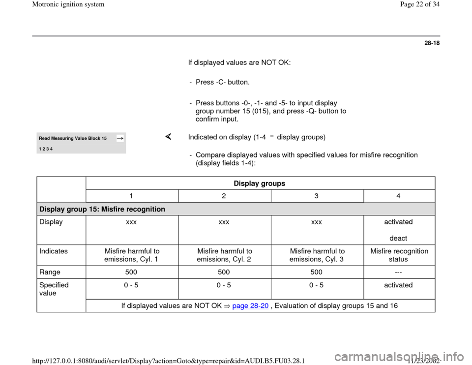
- Press buttons -0-, -1- and -5- to input display
group number 15 (015), and press -Q- button to
confirm input. Read Measuring Value Block 15 1 2 3 4
Indicated on display (1-4 display groups) - Compare displayed values with specified values for misfire recognition
(display fields 1-4):
Display groups
1 2 3 4
Display group 15: Misfire recognition
Display xxx xxx xxx activated
deact
Indicates Misfire harmful to
emissions, Cyl. 1 Misfire harmful to
emissions, Cyl. 2 Misfire harmful to
emissions, Cyl. 3 Misfire recognition
status
Range 500 500 500 ---
Specified
value 0 - 5 0 - 5 0 - 5 activated
If displayed values are NOT OK page 28
-20
, Evaluation of display groups 15 and 16
Pa
ge 22 of 34 Motronic i
gnition s
ystem
11/23/2002 htt
p://127.0.0.1:8080/audi/servlet/Dis
play?action=Goto&t
yp
e=re
pair&id=AUDI.B5.FU03.28.1
Page 23 of 34
28-19
If displayed values are OK:
- Press -C- button.
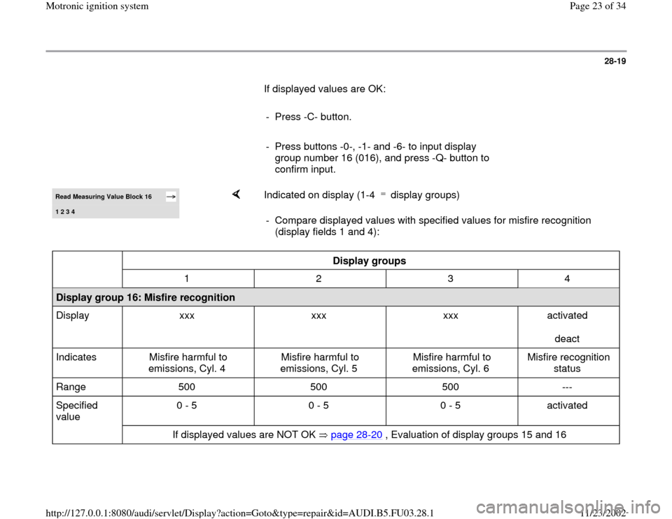
- Press buttons -0-, -1- and -6- to input display
group number 16 (016), and press -Q- button to
confirm input. Read Measuring Value Block 16 1 2 3 4
Indicated on display (1-4 display groups) - Compare displayed values with specified values for misfire recognition
(display fields 1 and 4):
Display groups
1 2 3 4
Display group 16: Misfire recognition
Display xxx xxx xxx activated
deact
Indicates Misfire harmful to
emissions, Cyl. 4 Misfire harmful to
emissions, Cyl. 5 Misfire harmful to
emissions, Cyl. 6 Misfire recognition
status
Range 500 500 500 ---
Specified
value 0 - 5 0 - 5 0 - 5 activated
If displayed values are NOT OK page 28
-20
, Evaluation of display groups 15 and 16
Pa
ge 23 of 34 Motronic i
gnition s
ystem
11/23/2002 htt
p://127.0.0.1:8080/audi/servlet/Dis
play?action=Goto&t
yp
e=re
pair&id=AUDI.B5.FU03.28.1