ignition AUDI A6 1999 C5 / 2.G AHA Engine Motronic Ignition System Workshop Manual
[x] Cancel search | Manufacturer: AUDI, Model Year: 1999, Model line: A6, Model: AUDI A6 1999 C5 / 2.GPages: 34, PDF Size: 0.19 MB
Page 1 of 34
28-1
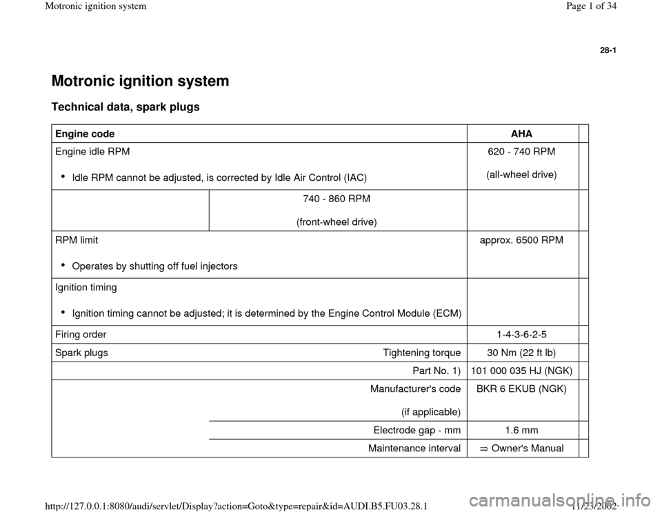
Motronic ignition system Technical data, spark plugs
Engine code
AHA
Engine idle RPM
Idle RPM cannot be adjusted, is corrected by Idle Air Control (IAC) 620 - 740 RPM
(all-wheel drive)
740 - 860 RPM
(front-wheel drive)
RPM limit
Operates by shutting off fuel injectors approx. 6500 RPM
Ignition timing
Ignition timing cannot be adjusted; it is determined by the Engine Control Module (ECM)
Firing order 1-4-3-6-2-5
Spark plugs Tightening torque 30 Nm (22 ft lb)
Part No. 1) 101 000 035 HJ (NGK)
Manufacturer's code
(if applicable) BKR 6 EKUB (NGK)
Electrode gap - mm 1.6 mm
Maintenance interval Owner's Manual
Pa
ge 1 of 34 Motronic i
gnition s
ystem
11/23/2002 htt
p://127.0.0.1:8080/audi/servlet/Dis
play?action=Goto&t
yp
e=re
pair&id=AUDI.B5.FU03.28.1
Page 4 of 34
28-3
Checking
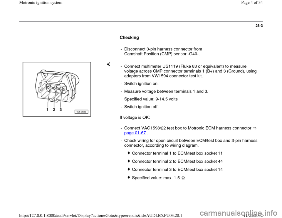
- Disconnect 3-pin harness connector from
Camshaft Position (CMP) sensor -G40-.
If voltage is OK: - Connect multimeter US1119 (Fluke 83 or equivalent) to measure
voltage across CMP connector terminals 1 (B+) and 3 (Ground), using
adapters from VW1594 connector test kit.
- Switch ignition on.
- Measure voltage between terminals 1 and 3.
Specified value: 9-14.5 volts
- Switch ignition off.
- Connect VAG1598/22 test box to Motronic ECM harness connector
page 01
-67
.
- Check wiring for open circuit between ECM/test box and 3-pin harness
connector, according to wiring diagram.
Connector terminal 1 to ECM/test box socket 11
Connector terminal 2 to ECM/test box socket 44
Connector terminal 3 to ECM/test box socket 14
Specified value: max. 1.5
Pa
ge 4 of 34 Motronic i
gnition s
ystem
11/23/2002 htt
p://127.0.0.1:8080/audi/servlet/Dis
play?action=Goto&t
yp
e=re
pair&id=AUDI.B5.FU03.28.1
Page 7 of 34
28-6
Checking
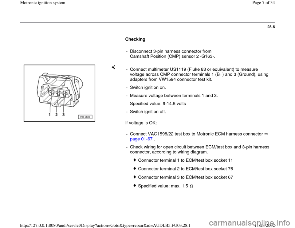
- Disconnect 3-pin harness connector from
Camshaft Position (CMP) sensor 2 -G163-.
If voltage is OK: - Connect multimeter US1119 (Fluke 83 or equivalent) to measure
voltage across CMP connector terminals 1 (B+) and 3 (Ground), using
adapters from VW1594 connector test kit.
- Switch ignition on.
- Measure voltage between terminals 1 and 3.
Specified value: 9-14.5 volts
- Switch ignition off.
- Connect VAG1598/22 test box to Motronic ECM harness connector
page 01
-67
.
- Check wiring for open circuit between ECM/test box and 3-pin harness
connector, according to wiring diagram.
Connector terminal 1 to ECM/test box socket 11
Connector terminal 2 to ECM/test box socket 76
Connector terminal 3 to ECM/test box socket 67
Specified value: max. 1.5
Pa
ge 7 of 34 Motronic i
gnition s
ystem
11/23/2002 htt
p://127.0.0.1:8080/audi/servlet/Dis
play?action=Goto&t
yp
e=re
pair&id=AUDI.B5.FU03.28.1
Page 12 of 34
28-10
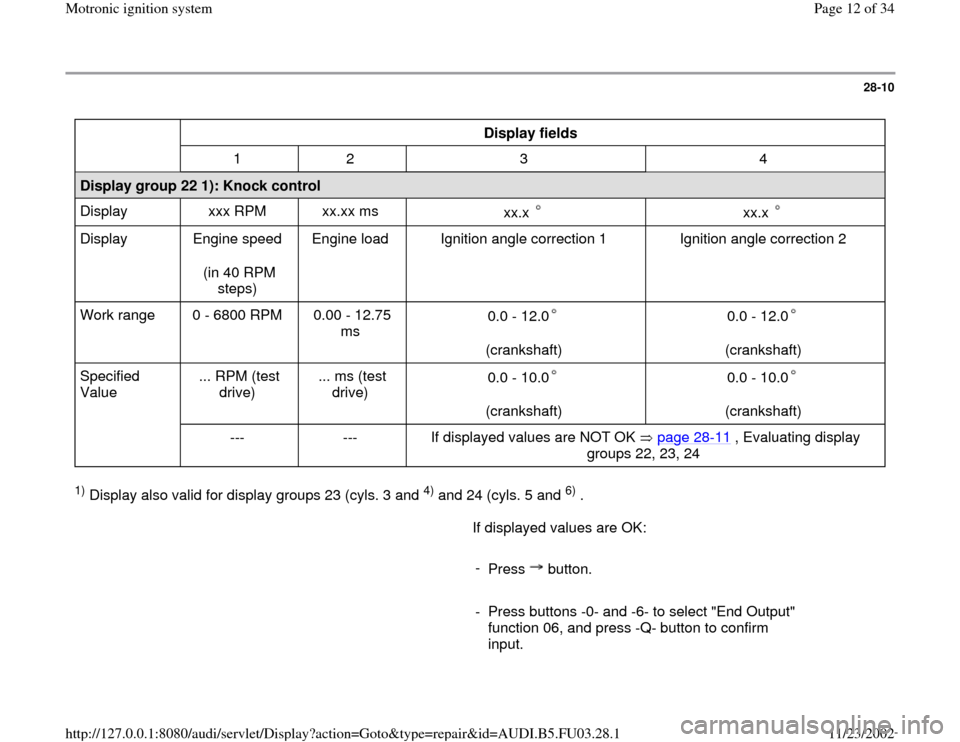
Display fields
1 2 3 4
Display group 22 1): Knock control
Display xxx RPM xx.xx ms
xx.x
xx.x
Display Engine speed
(in 40 RPM
steps) Engine load Ignition angle correction 1 Ignition angle correction 2
Work range 0 - 6800 RPM 0.00 - 12.75
ms 0.0 - 12.0
(crankshaft)
0.0 - 12.0
(crankshaft)
Specified
Value ... RPM (test
drive) ... ms (test
drive) 0.0 - 10.0
(crankshaft)
0.0 - 10.0
(crankshaft)
--- --- If displayed values are NOT OK page 28
-11
, Evaluating display
groups 22, 23, 24
1) Display also valid for display groups 23 (cyls. 3 and
4) and 24 (cyls. 5 and
6) .
If displayed values are OK:
-
Press button.
- Press buttons -0- and -6- to select "End Output"
function 06, and press -Q- button to confirm
input.
Pa
ge 12 of 34 Motronic i
gnition s
ystem
11/23/2002 htt
p://127.0.0.1:8080/audi/servlet/Dis
play?action=Goto&t
yp
e=re
pair&id=AUDI.B5.FU03.28.1
Page 24 of 34
28-20
Evaluation of display groups 15 and 16 Display groups: 15
and 16
Display fields: 2 and
3
Possible malfunction cause
Corrective action
greater than 5
Ignition coil faulty
Spark plug connector faulty
Spark plug faulty
Power output stage for
ignition coil faulty - Check ignition coils -N-, -N128- and -N158- with power output
stage -N122 page 28
-21
Fuel injector faulty
Not enough fuel- Check fuel injectors page 24
-102
- Check fuel in tank
Pa
ge 24 of 34 Motronic i
gnition s
ystem
11/23/2002 htt
p://127.0.0.1:8080/audi/servlet/Dis
play?action=Goto&t
yp
e=re
pair&id=AUDI.B5.FU03.28.1
Page 25 of 34
28-21
Ignition coils and power output stage,
checking
Notes:
The ignition coils and power output stage are
one component.
Measuring the primary resistance of the ignition
coils is not possible.
Measure secondary resistance first with ignition
wires connected to the ignition coil via the spark
plug connector of the respective cylinder (with
this method the interference resistances of the
ignition cables are also measured).
Component locations page 24
-1
Required special tools and test equipment
Multimeter US1119 (Fluke 83 or equivalent)
VW1594 connector test kit
Test conditions
No fuel injector malfunction stored in DTC
Pa
ge 25 of 34 Motronic i
gnition s
ystem
11/23/2002 htt
p://127.0.0.1:8080/audi/servlet/Dis
play?action=Goto&t
yp
e=re
pair&id=AUDI.B5.FU03.28.1
Page 28 of 34
that is OK.
If a different cylinder now misfires:
- Replace faulty spark plug.
If the original cylinder misfires:
- Check ignition coil page 28
-23
.
Pa
ge 28 of 34 Motronic i
gnition s
ystem
11/23/2002 htt
p://127.0.0.1:8080/audi/servlet/Dis
play?action=Goto&t
yp
e=re
pair&id=AUDI.B5.FU03.28.1
Page 29 of 34
28-23
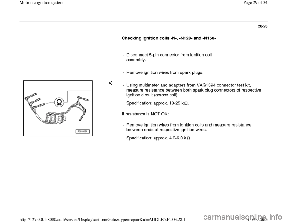
Checking ignition coils -N-, -N128- and -N158-
- Disconnect 5-pin connector from ignition coil
assembly.
- Remove ignition wires from spark plugs.
If resistance is NOT OK: - Using multimeter and adapters from VAG1594 connector test kit,
measure resistance between both spark plug connectors of respective
ignition circuit (across coil).
Specification: approx. 18-25 k .- Remove ignition wires from ignition coils and measure resistance
between ends of respective ignition wires.
Specification: approx. 4.0-6.0 k
Pa
ge 29 of 34 Motronic i
gnition s
ystem
11/23/2002 htt
p://127.0.0.1:8080/audi/servlet/Dis
play?action=Goto&t
yp
e=re
pair&id=AUDI.B5.FU03.28.1
Page 30 of 34
28-24
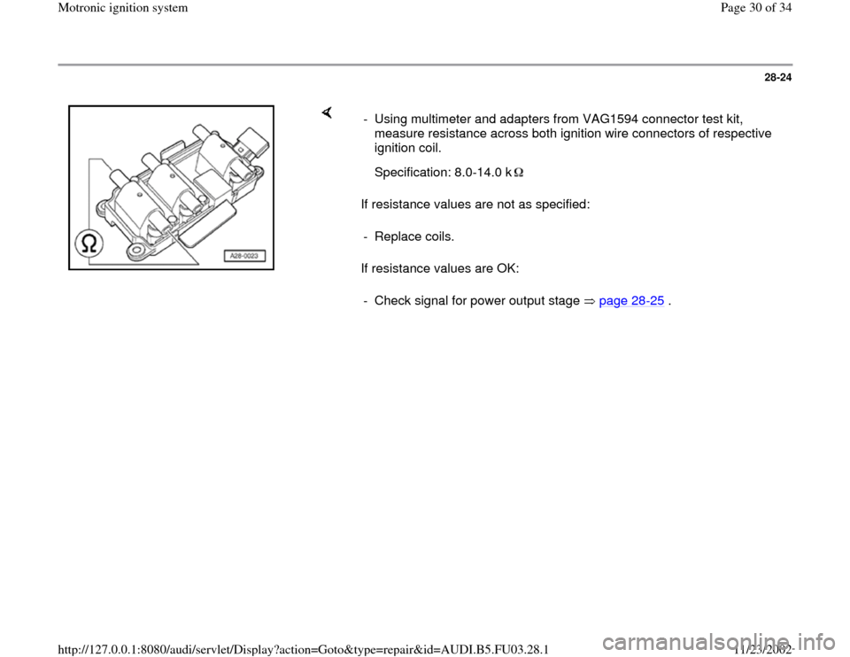
If resistance values are not as specified:
If resistance values are OK: - Using multimeter and adapters from VAG1594 connector test kit,
measure resistance across both ignition wire connectors of respective
ignition coil.
Specification: 8.0-14.0 k - Replace coils.
- Check signal for power output stage page 28
-25
.
Pa
ge 30 of 34 Motronic i
gnition s
ystem
11/23/2002 htt
p://127.0.0.1:8080/audi/servlet/Dis
play?action=Goto&t
yp
e=re
pair&id=AUDI.B5.FU03.28.1
Page 31 of 34
28-25
Checking signal for power output stage
- Remove connectors from all 6 injectors (DTC
memory will have to be checked and erased
later).
- Switch ignition on.
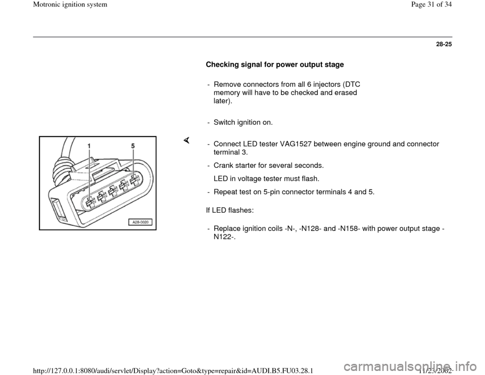
If LED flashes: - Connect LED tester VAG1527 between engine ground and connector
terminal 3.
- Crank starter for several seconds.
LED in voltage tester must flash.
- Repeat test on 5-pin connector terminals 4 and 5.
- Replace ignition coils -N-, -N128- and -N158- with power output stage -
N122-.
Pa
ge 31 of 34 Motronic i
gnition s
ystem
11/23/2002 htt
p://127.0.0.1:8080/audi/servlet/Dis
play?action=Goto&t
yp
e=re
pair&id=AUDI.B5.FU03.28.1