warning AUDI A6 2000 C5 / 2.G AEB ATW Engines Turbocharger System Workshop Manual
[x] Cancel search | Manufacturer: AUDI, Model Year: 2000, Model line: A6, Model: AUDI A6 2000 C5 / 2.GPages: 50, PDF Size: 0.63 MB
Page 6 of 50
21-5
Turbocharger and wastegate, checking
If special testing equipment is required during
test drive, heed the following WARNING:
WARNING!
When driving or riding in an airbag-equipped
vehicle, NEVER hold the scan tool or other
test equipment in your hands or lap while in
motion. Objects between you and the airbag
increase the risk of injury in an accident.
During a test drive in an airbag-equipped
vehicle, test equipment must always be
fastened to and operated from the rear seat
by a second technician.
Special tools and equipment
VAG1397A turbocharger tester
VAG1551 scan tool with VAG1551/3 adapter
Pa
ge 6 of 50 Turbochar
ger s
ystem
11/18/2002 htt
p://127.0.0.1:8080/audi/servlet/Dis
play?action=Goto&t
yp
e=re
pair&id=AUDI.B5.GE02.21.1
Page 8 of 50
21-7
Note:
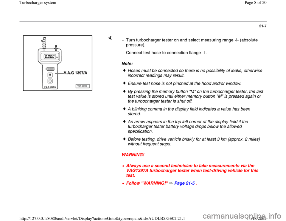
WARNING! - Turn turbocharger tester on and select measuring range -I- (absolute
pressure).
- Connect test hose to connection flange -I-.
Hoses must be connected so there is no possibility of leaks, otherwise
incorrect readings may result. Ensure test hose is not pinched at the hood and/or window.By pressing the memory button "M" on the turbocharger tester, the last
test value is stored until either memory button "M" is pressed again or
the turbocharger tester is shut off. A blinking comma in the display field indicates a value has been
stored. An arrow appears in the top left corner of the display field if the
turbocharger tester battery voltage drops below the allowed
specification. Before testing, drive vehicle briskly for at least 3 km (approx. 2 miles)
without frequent stops. Always use a second technician to take measurements via the
VAG1397A turbocharger tester when test-driving vehicle for this
test. Follow "WARNING!" Page 21
-5 .
Pa
ge 8 of 50 Turbochar
ger s
ystem
11/18/2002 htt
p://127.0.0.1:8080/audi/servlet/Dis
play?action=Goto&t
yp
e=re
pair&id=AUDI.B5.GE02.21.1
Page 11 of 50
21-10
Charge air pressure control (via load
signal), checking
WARNING!
Always use a second technician to take
measurements via the VAG1397A
turbocharger tester when test-driving vehicle
for this test.
Follow "WARNING!" Page 21
-5 .
Note:
If VAG1551 scan tool is not available, use
VAG1552 mobile scan tool instead.
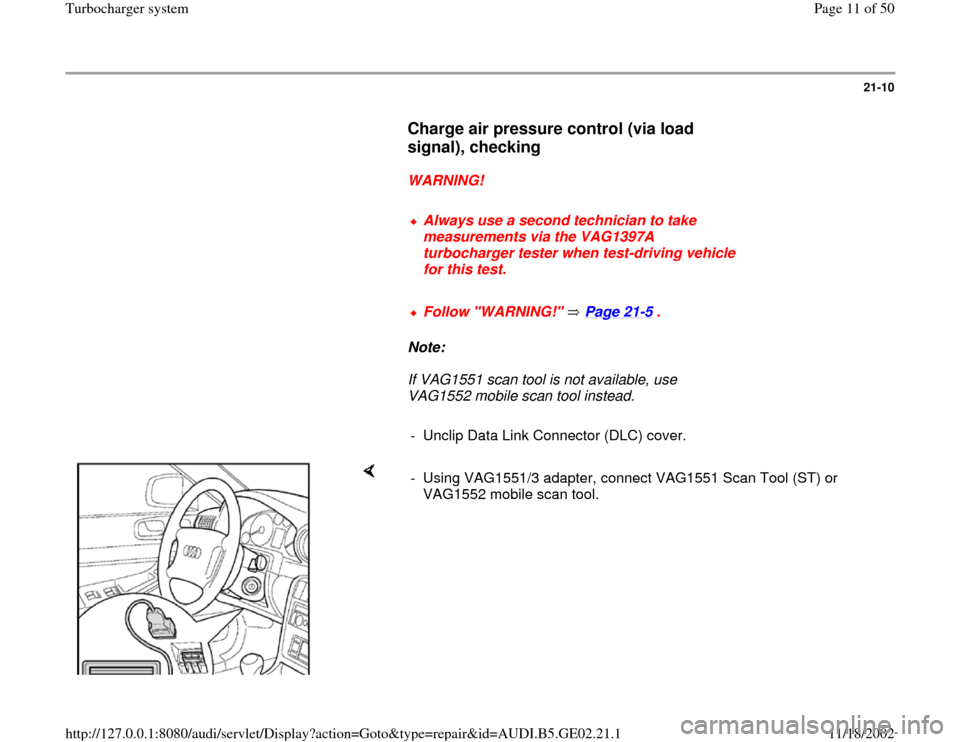
- Unclip Data Link Connector (DLC) cover.
- Using VAG1551/3 adapter, connect VAG1551 Scan Tool (ST) or
VAG1552 mobile scan tool.
Pa
ge 11 of 50 Turbochar
ger s
ystem
11/18/2002 htt
p://127.0.0.1:8080/audi/servlet/Dis
play?action=Goto&t
yp
e=re
pair&id=AUDI.B5.GE02.21.1
Page 18 of 50
The shop air supply line will later be attached to the inlet of VAG 1687. - Close valve -3- before gauge.
- Close valve -4- after gauge.
- Remove female fitting from tester (arrow) and install an appropriate
"male" air fitting that will connect to your shop air supply line (
WARNING!).
Pa
ge 18 of 50 Turbochar
ger s
ystem
11/18/2002 htt
p://127.0.0.1:8080/audi/servlet/Dis
play?action=Goto&t
yp
e=re
pair&id=AUDI.B5.GE02.21.1
Page 19 of 50
21-15
WARNING!
Use only approved air fittings to adapt shop
air supply line to VAG 1687 tester.
Special tool VAG 1687/1 pressure adapter,
installing (1.8L Turbo)
- Separate intake hose from Mass Air Flow (MAF)
sensor assembly.
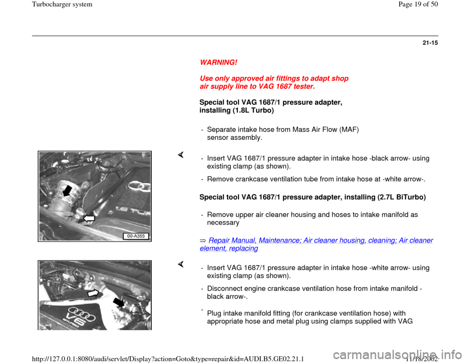
Special tool VAG 1687/1 pressure adapter, installing (2.7L BiTurbo)
Repair Manual, Maintenance; Air cleaner housing, cleaning; Air cleaner element, replacing
- Insert VAG 1687/1 pressure adapter in intake hose -black arrow- using
existing clamp (as shown).
- Remove crankcase ventilation tube from intake hose at -white arrow-.
- Remove upper air cleaner housing and hoses to intake manifold as
necessary
- Insert VAG 1687/1 pressure adapter in intake hose -white arrow- using
existing clamp (as shown).
- Disconnect engine crankcase ventilation hose from intake manifold -
black arrow-.
-
Plug intake manifold fitting (for crankcase ventilation hose) with
appropriate hose and metal plug using clamps supplied with VAG
Pa
ge 19 of 50 Turbochar
ger s
ystem
11/18/2002 htt
p://127.0.0.1:8080/audi/servlet/Dis
play?action=Goto&t
yp
e=re
pair&id=AUDI.B5.GE02.21.1
Page 39 of 50
21-30
Turbocharger, removing and installing
Note:
Replace gaskets and self-locking nuts.
Removing
WARNING!
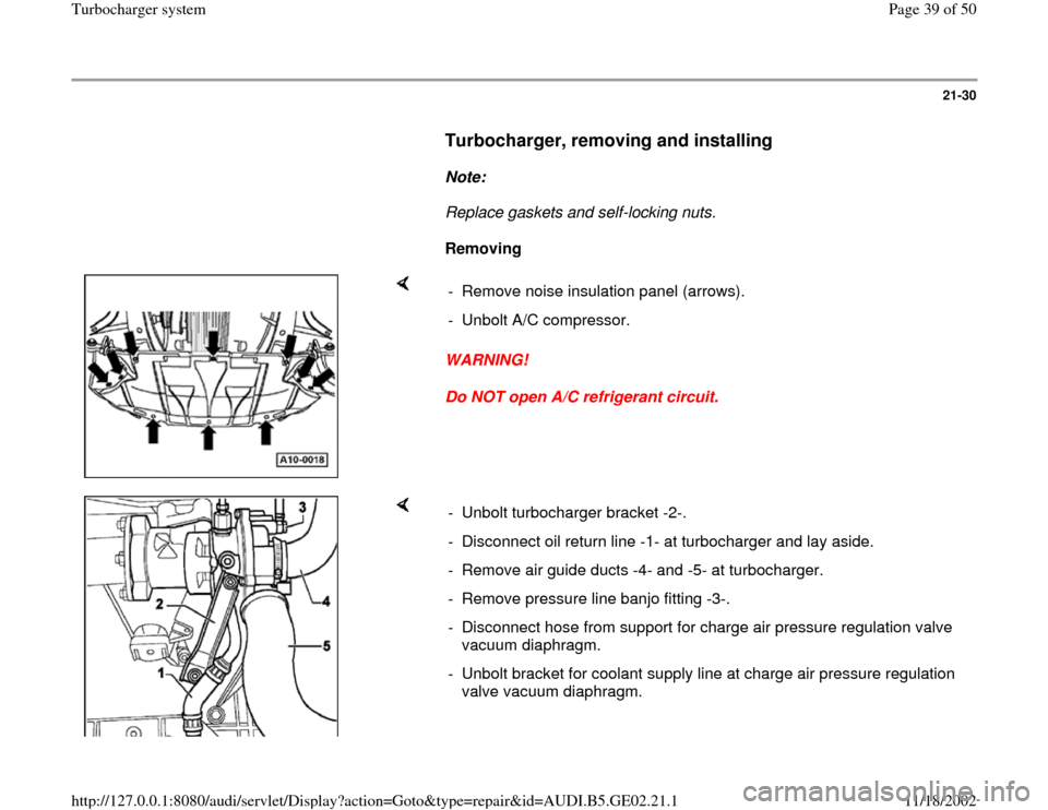
Do NOT open A/C refrigerant circuit. - Remove noise insulation panel (arrows).
- Unbolt A/C compressor.
- Unbolt turbocharger bracket -2-.
- Disconnect oil return line -1- at turbocharger and lay aside.
- Remove air guide ducts -4- and -5- at turbocharger.
- Remove pressure line banjo fitting -3-.
- Disconnect hose from support for charge air pressure regulation valve
vacuum diaphragm.
- Unbolt bracket for coolant supply line at charge air pressure regulation
valve vacuum diaphragm.
Pa
ge 39 of 50 Turbochar
ger s
ystem
11/18/2002 htt
p://127.0.0.1:8080/audi/servlet/Dis
play?action=Goto&t
yp
e=re
pair&id=AUDI.B5.GE02.21.1
Page 45 of 50
21-33
Note:
Add oil to turbocharger through oil supply line
connection flange.
- Fill up coolant Page 19
-4 .
WARNING!
The cooling system is pressurized when the
engine is warm. When opening the expansion
tank, wear gloves and other appropriate
protection, cover the cap with a cloth and
open carefully to relieve system pressure
slowly.
Note:
After installing the turbocharger, let engine idle
for approx. 1 minute without increasing engine
speed. This ensures adequate oil supply to the
turbocharger.
- Check engine oil level Page 17
-27
.
Pa
ge 45 of 50 Turbochar
ger s
ystem
11/18/2002 htt
p://127.0.0.1:8080/audi/servlet/Dis
play?action=Goto&t
yp
e=re
pair&id=AUDI.B5.GE02.21.1