oil AUDI A6 2000 C5 / 2.G AEB ATW Engines Valvetrain Servicing Workshop Manual
[x] Cancel search | Manufacturer: AUDI, Model Year: 2000, Model line: A6, Model: AUDI A6 2000 C5 / 2.GPages: 51, PDF Size: 0.8 MB
Page 2 of 51
15-33
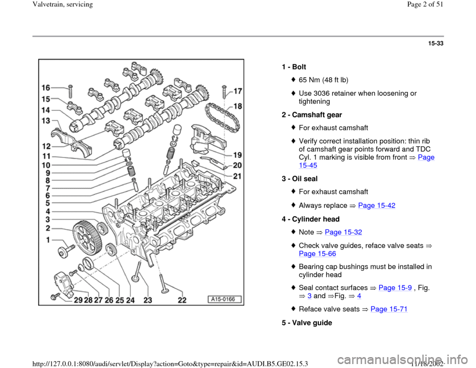
1 -
Bolt
65 Nm (48 ft lb)Use 3036 retainer when loosening or
tightening
2 -
Camshaft gear For exhaust camshaftVerify correct installation position: thin rib
of camshaft gear points forward and TDC
Cyl. 1 marking is visible from front Page 15
-45
3 -
Oil seal
For exhaust camshaftAlways replace Page 15
-42
4 -
Cylinder head
Note Page 15
-32
Check valve guides, reface valve seats
Page 15
-66
Bearing cap bushings must be installed in
cylinder head Seal contact surfaces Page 15
-9 , Fig.
3
and Fig. 4
Reface valve seats Page 15
-71
5 -
Valve guide
Pa
ge 2 of 51 Valvetrain, servicin
g
11/18/2002 htt
p://127.0.0.1:8080/audi/servlet/Dis
play?action=Goto&t
yp
e=re
pair&id=AUDI.B5.GE02.15.3
Page 4 of 51
15-34
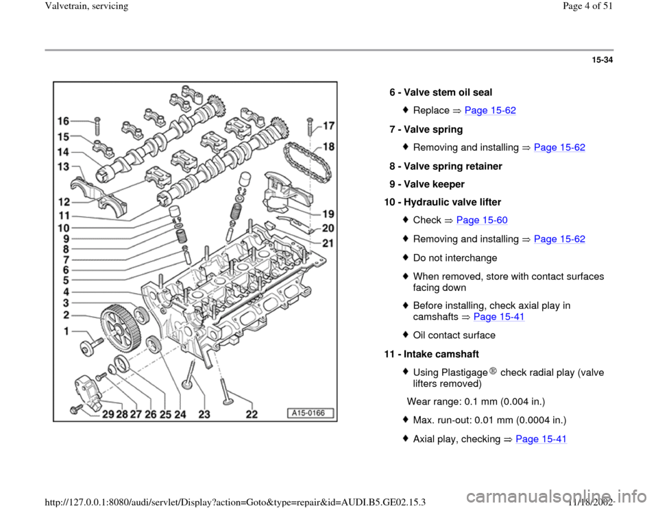
6 -
Valve stem oil seal
Replace Page 15
-62
7 -
Valve spring
Removing and installing Page 15
-62
8 -
Valve spring retainer
9 -
Valve keeper
10 -
Hydraulic valve lifter
Check Page 15
-60
Removing and installing Page 15
-62
Do not interchangeWhen removed, store with contact surfaces
facing down Before installing, check axial play in
camshafts Page 15
-41
Oil contact surface
11 -
Intake camshaft Using Plastigage check radial play (valve
lifters removed)
Wear range: 0.1 mm (0.004 in.)
Max. run-out: 0.01 mm (0.0004 in.)Axial play, checking Page 15
-41Pa
ge 4 of 51 Valvetrain, servicin
g
11/18/2002 htt
p://127.0.0.1:8080/audi/servlet/Dis
play?action=Goto&t
yp
e=re
pair&id=AUDI.B5.GE02.15.3
Page 9 of 51
15-38
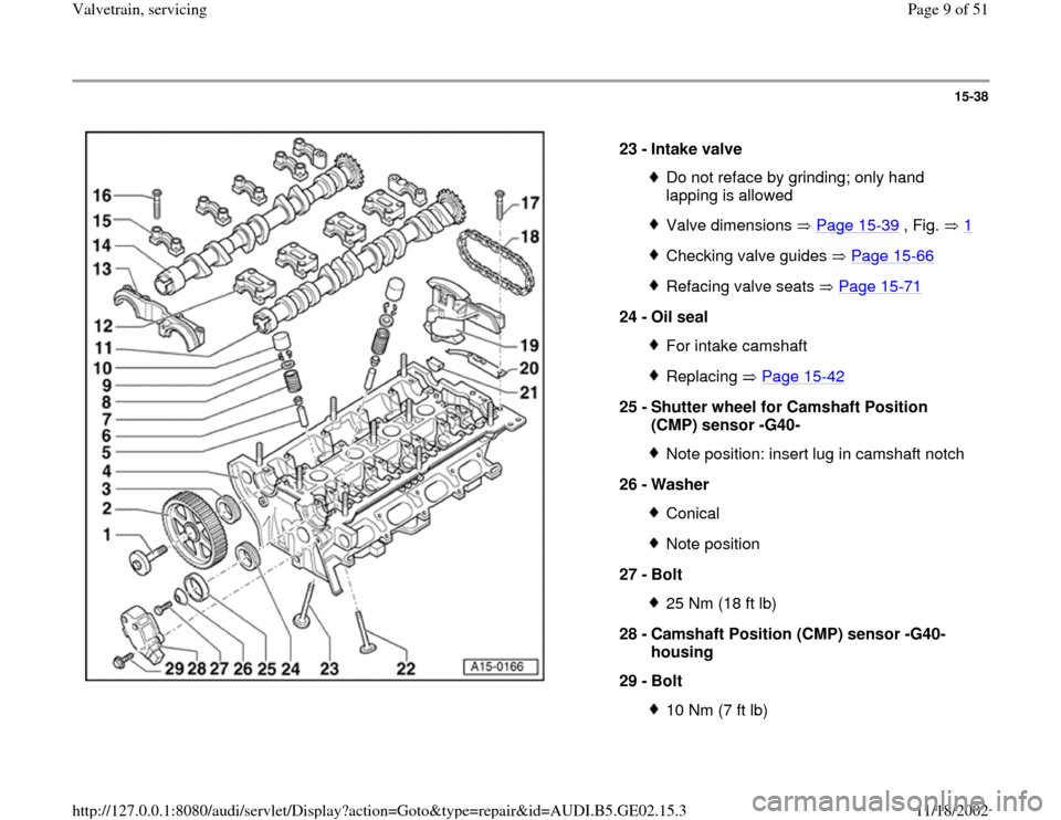
23 -
Intake valve
Do not reface by grinding; only hand
lapping is allowed Valve dimensions Page 15
-39
, Fig. 1
Checking valve guides Page 15
-66
Refacing valve seats Page 15
-71
24 -
Oil seal
For intake camshaftReplacing Page 15
-42
25 -
Shutter wheel for Camshaft Position
(CMP) sensor -G40-
Note position: insert lug in camshaft notch
26 -
Washer ConicalNote position
27 -
Bolt 25 Nm (18 ft lb)
28 -
Camshaft Position (CMP) sensor -G40-
housing
29 -
Bolt 10 Nm (7 ft lb)
Pa
ge 9 of 51 Valvetrain, servicin
g
11/18/2002 htt
p://127.0.0.1:8080/audi/servlet/Dis
play?action=Goto&t
yp
e=re
pair&id=AUDI.B5.GE02.15.3
Page 14 of 51
15-42
Oil seals for camshafts, replacing
Cylinder head installed
Lock carrier in service position Page 13
-1
Special tools and equipment
2085 seal puller
3241 seal installer
3036 retainer
Replacing exhaust camshaft oil seal
Removing
- Remove ribbed belt and ribbed belt tensioner
Page 13
-15
.
- Remove engine covers.
- Remove upper toothed belt cover Page 13
-
29
.
-
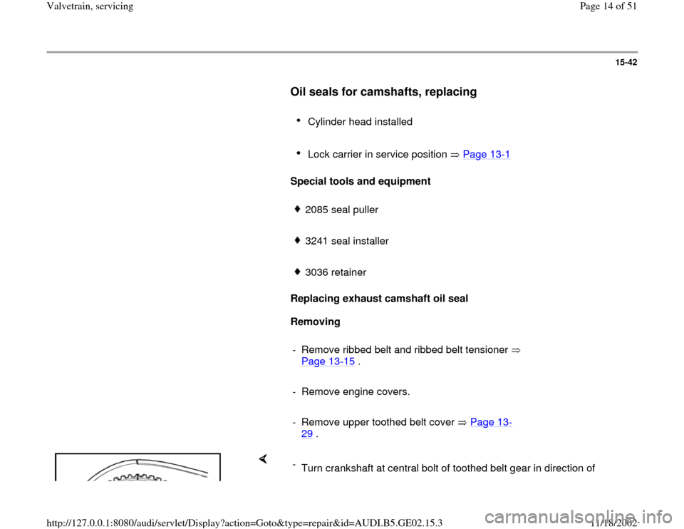
Turn crankshaft at central bolt of toothed belt gear in direction of
Pa
ge 14 of 51 Valvetrain, servicin
g
11/18/2002 htt
p://127.0.0.1:8080/audi/servlet/Dis
play?action=Goto&t
yp
e=re
pair&id=AUDI.B5.GE02.15.3
Page 17 of 51
15-44
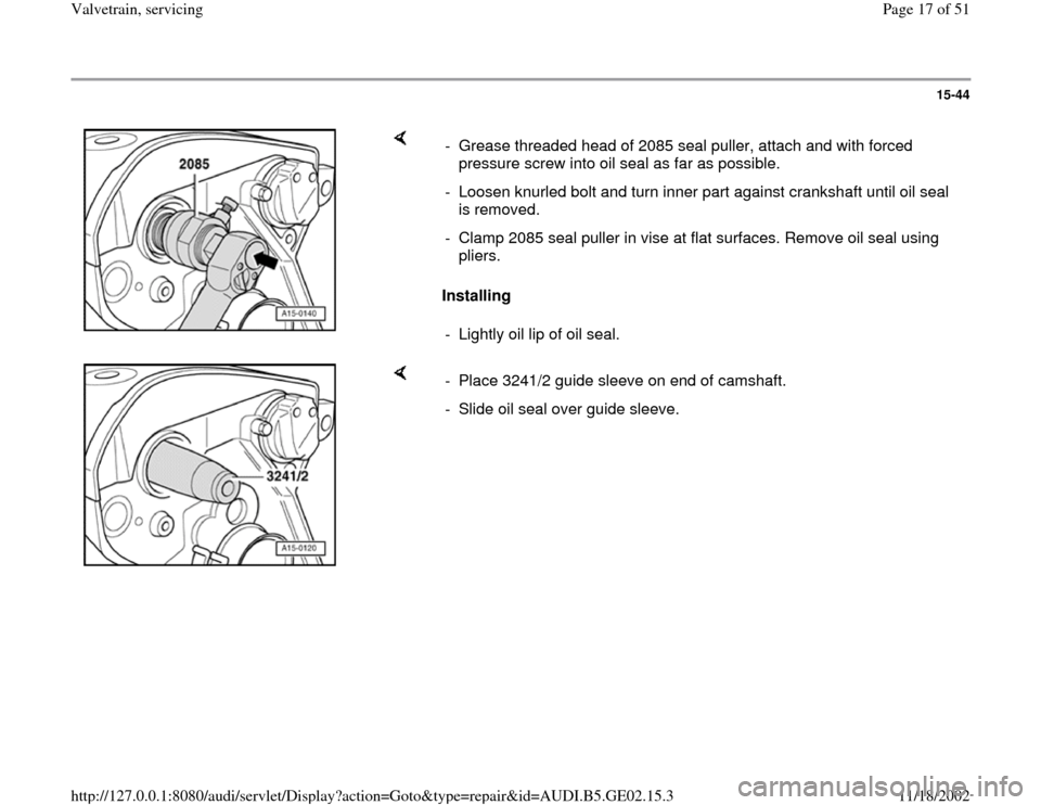
Installing - Grease threaded head of 2085 seal puller, attach and with forced
pressure screw into oil seal as far as possible.
- Loosen knurled bolt and turn inner part against crankshaft until oil seal
is removed.
- Clamp 2085 seal puller in vise at flat surfaces. Remove oil seal using
pliers.
- Lightly oil lip of oil seal.
- Place 3241/2 guide sleeve on end of camshaft.
- Slide oil seal over guide sleeve.
Pa
ge 17 of 51 Valvetrain, servicin
g
11/18/2002 htt
p://127.0.0.1:8080/audi/servlet/Dis
play?action=Goto&t
yp
e=re
pair&id=AUDI.B5.GE02.15.3
Page 18 of 51
15-45
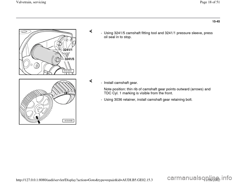
- Using 3241/5 camshaft fitting tool and 3241/1 pressure sleeve, press
oil seal in to stop.
- Install camshaft gear.
Note position: thin rib of camshaft gear points outward (arrows) and
TDC Cyl. 1 marking is visible from the front.
- Using 3036 retainer, install camshaft gear retaining bolt.
Pa
ge 18 of 51 Valvetrain, servicin
g
11/18/2002 htt
p://127.0.0.1:8080/audi/servlet/Dis
play?action=Goto&t
yp
e=re
pair&id=AUDI.B5.GE02.15.3
Page 20 of 51
15-47
Replacing intake camshaft oil seal
Removing
- Remove ribbed belt and ribbed belt tensioner
Page 13
-15
.
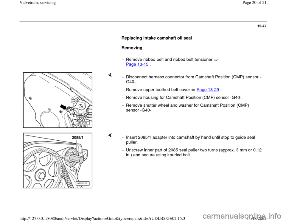
- Disconnect harness connector from Camshaft Position (CMP) sensor -
G40-.
- Remove upper toothed belt cover Page 13
-29
.
- Remove housing for Camshaft Position (CMP) sensor -G40-.
- Remove shutter wheel and washer for Camshaft Position (CMP)
sensor -G40-.
- Insert 2085/1 adapter into camshaft by hand until stop to guide seal
puller.
- Unscrew inner part of 2085 seal puller two turns (approx. 3 mm or 0.12
in.) and secure using knurled bolt.
Pa
ge 20 of 51 Valvetrain, servicin
g
11/18/2002 htt
p://127.0.0.1:8080/audi/servlet/Dis
play?action=Goto&t
yp
e=re
pair&id=AUDI.B5.GE02.15.3
Page 21 of 51
15-48
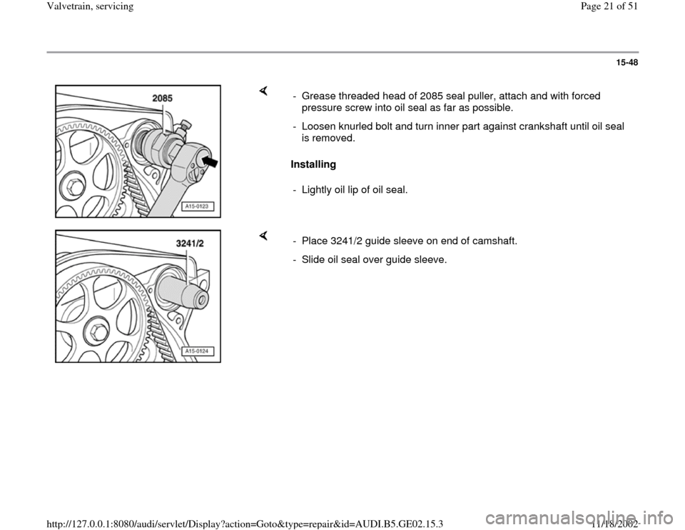
Installing - Grease threaded head of 2085 seal puller, attach and with forced
pressure screw into oil seal as far as possible.
- Loosen knurled bolt and turn inner part against crankshaft until oil seal
is removed.
- Lightly oil lip of oil seal.
- Place 3241/2 guide sleeve on end of camshaft.
- Slide oil seal over guide sleeve.
Pa
ge 21 of 51 Valvetrain, servicin
g
11/18/2002 htt
p://127.0.0.1:8080/audi/servlet/Dis
play?action=Goto&t
yp
e=re
pair&id=AUDI.B5.GE02.15.3
Page 22 of 51
15-49
Note:
When installing ribbed belt, make sure it is seated correctly on the pulleys.
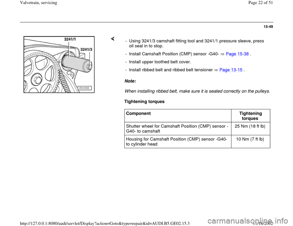
Tightening torques - Using 3241/3 camshaft fitting tool and 3241/1 pressure sleeve, press
oil seal in to stop.
- Install Camshaft Position (CMP) sensor -G40- Page 15
-38
.
- Install upper toothed belt cover.
- Install ribbed belt and ribbed belt tensioner Page 13
-15
.
Component
Tightening
torques
Shutter wheel for Camshaft Position (CMP) sensor -
G40- to camshaft 25 Nm (18 ft lb)
Housing for Camshaft Position (CMP) sensor -G40-
to cylinder head 10 Nm (7 ft lb)
Pa
ge 22 of 51 Valvetrain, servicin
g
11/18/2002 htt
p://127.0.0.1:8080/audi/servlet/Dis
play?action=Goto&t
yp
e=re
pair&id=AUDI.B5.GE02.15.3
Page 29 of 51
15-55
- Install camshafts with drive chain and hydraulic
chain tensioner into cylinder head.
- Oil camshaft contact surfaces.
Note:
Alignment bushings for bearing caps and
hydraulic chain tensioner must be installed in
cylinder head.
When installing bearing caps, verify marking on
cap is readable from intake side of cylinder
head.
- Tighten hydraulic chain tensioner (pay attention
to alignment bushings).
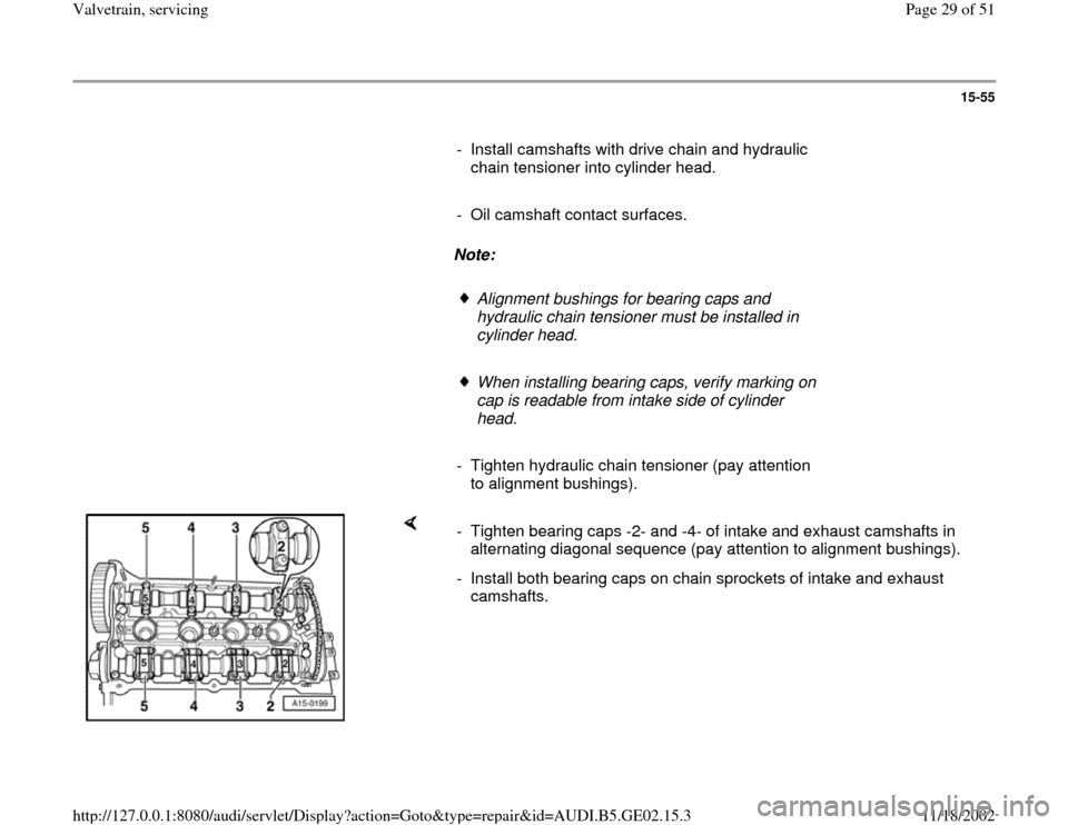
- Tighten bearing caps -2- and -4- of intake and exhaust camshafts in
alternating diagonal sequence (pay attention to alignment bushings).
- Install both bearing caps on chain sprockets of intake and exhaust
camshafts.
Pa
ge 29 of 51 Valvetrain, servicin
g
11/18/2002 htt
p://127.0.0.1:8080/audi/servlet/Dis
play?action=Goto&t
yp
e=re
pair&id=AUDI.B5.GE02.15.3