ECU AUDI A6 2000 C5 / 2.G Changing Clutch 5Speed Manual Gearbox
[x] Cancel search | Manufacturer: AUDI, Model Year: 2000, Model line: A6, Model: AUDI A6 2000 C5 / 2.GPages: 71, PDF Size: 1.82 MB
Page 23 of 71
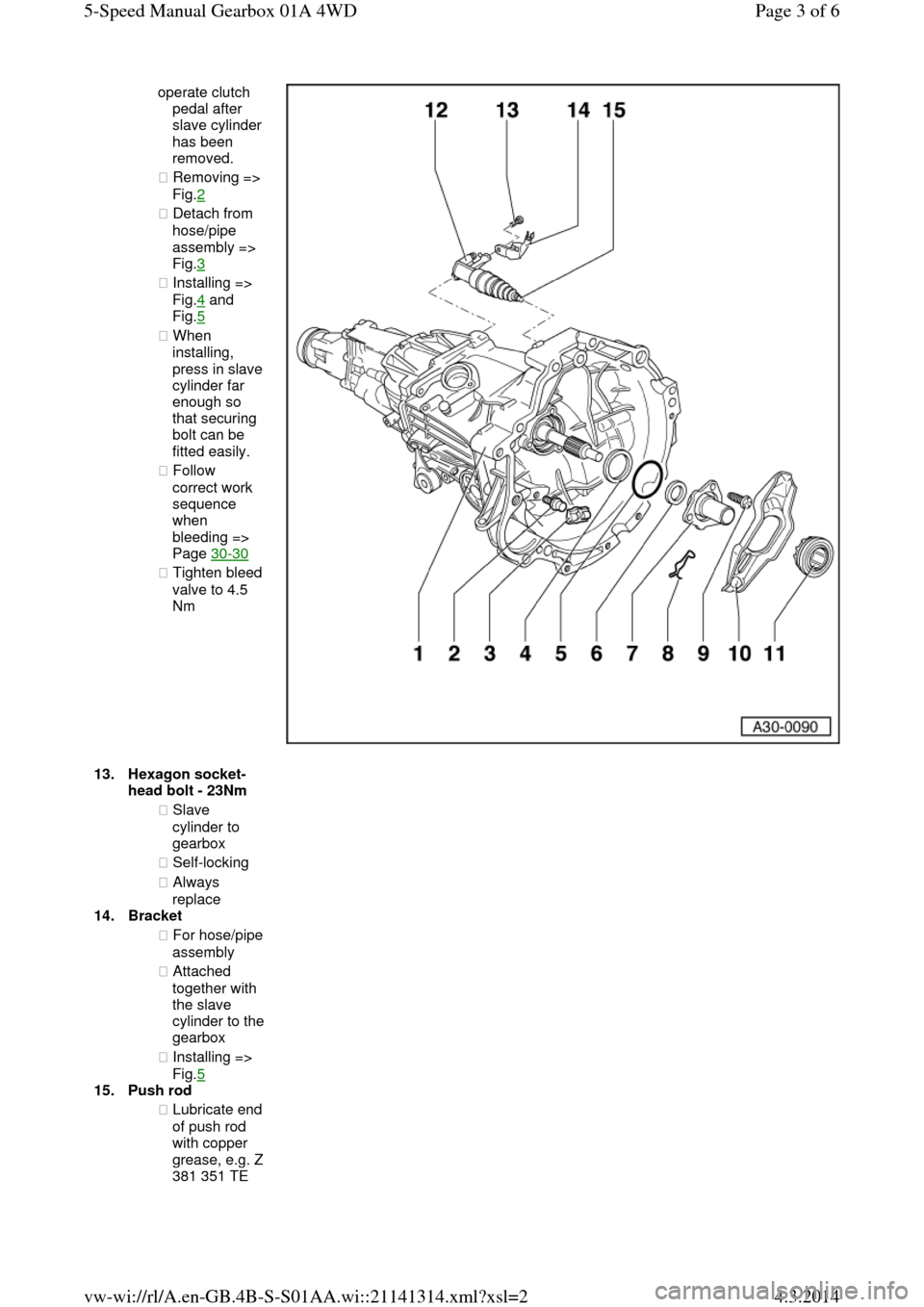
operate clutch
pedal after slave cylinder has been
removed.
◆ Removing => Fig.2
◆ Detach from
hose/pipe
assembly =>
Fig.3
◆ Installing =>
Fig.4 and
Fig.5
◆ When
installing, press in slave cylinder far
enough so
that securing
bolt can be
fitted easily.
◆ Follow
correct work
sequence
when
bleeding =>
Page 30-30
◆ Tighten bleed valve to 4.5
Nm 13.Hexagon socket-head bolt - 23Nm
◆ Slave
cylinder to
gearbox
◆ Self-locking
◆ Always
replace
14.Bracket
◆ For hose/pipe assembly
◆ Attached
together with
the slave cylinder to the gearbox
◆ Installing =>
Fig.5
15.Push rod
◆ Lubricate end of push rod
with copper grease, e.g. Z 381 351 TE Page 3 of 65-Speed Manual Gearbox 01A 4WD4.3.2014vw-wi://rl/A.en-GB.4B-S-S01AA.wi::21141314.xml?xsl=2
Page 26 of 71
off-line there is a danger that the push rod
will be guided past the clutch release
lever.
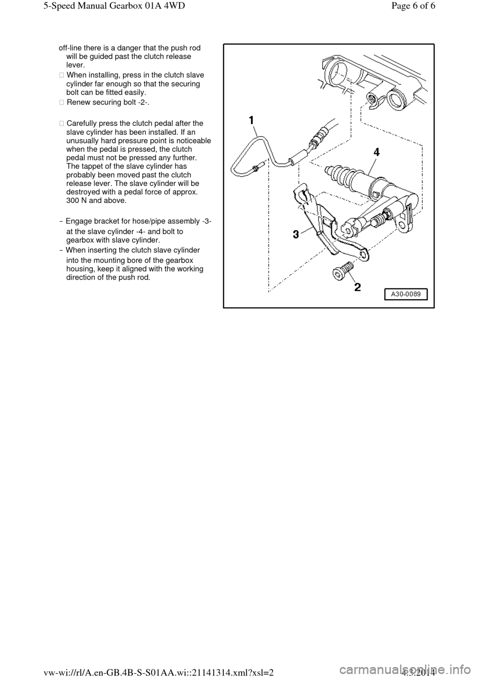
◆ When installing, press in the clutch slave
cylinder far enough so that the securing
bolt can be fitted easily.
◆ Renew securing bolt -2-.
◆ Carefully press the clutch pedal after the
slave cylinder has been installed. If an unusually hard pressure point is noticeable when the pedal is pressed, the clutch
pedal must not be pressed any further.
The tappet of the slave cylinder has
probably been moved past the clutch
release lever. The slave cylinder will be
destroyed with a pedal force of approx.
300 N and above.
‒ Engage bracket for hose/pipe assembly -3- at the slave cylinder -4- and bolt to
gearbox with slave cylinder.
‒ When inserting the clutch slave cylinder
into the mounting bore of the gearbox
housing, keep it aligned with the working
direction of the push rod. Page 6 of 65-Speed Manual Gearbox 01A 4WD4.3.2014vw-wi://rl/A.en-GB.4B-S-S01AA.wi::21141314.xml?xsl=2
Page 28 of 71
plates) the hub splines.
Remove corrosion
and apply only a very thin coating of grease G 000 100 to the
splines. Then move clutch plate to and for on input shaft until
hub moves freely on
shaft. Excess grease
must be removed.
◆ Pressure plates are
protected against
corrosion and
greased. Only the
contact surface may be cleaned, otherwise the service life of the
clutch will be
considerably
reduced.
◆ Tighten securing
bolts in small steps in
diagonal sequence to
avoid damaging
centring holes in
pressure plate and
centring pins on
flywheel.
‒ Remove the gearbox
to work on the
clutch=>Page 34-35.
1.Flywheel/dual mass
flywheel
◆ Ensure that
centring pins
are a tight fit.
◆ Contact
surface for
clutch lining must be free of grooves, oil
and grease
◆ Observe
removal
instructions for
the weight-
optimised dual-
mass flywheel
=>Fig.2
◆ Removing and
installing:
=> Relevant
engine
workshop
manual,
Mechanical
components;
Repair group
13 Page 2 of 75-Speed Manual Gearbox 01A 4WD4.3.2014vw-wi://rl/A.en-GB.4B-S-S01AA.wi::21141315.xml?xsl=2
Page 31 of 71
installing:
=> Relevant
engine
workshop
manual,
Mechanical
components;
Repair group
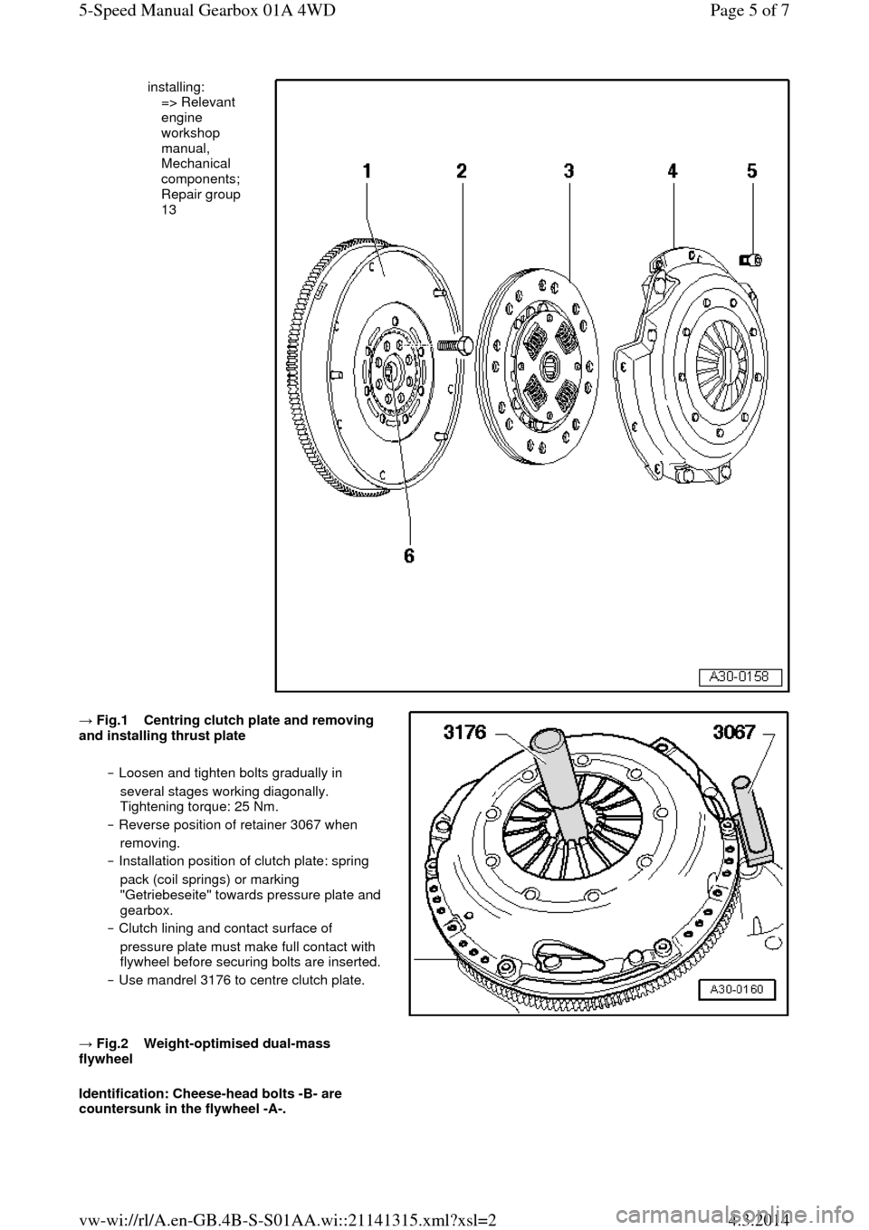
13 → Fig.1 Centring clutch plate and removing and installing thrust plate
‒ Loosen and tighten bolts gradually in
several stages working diagonally.
Tightening torque: 25 Nm.
‒ Reverse position of retainer 3067 when
removing.
‒ Installation position of clutch plate: spring
pack (coil springs) or marking
"Getriebeseite" towards pressure plate and
gearbox.
‒ Clutch lining and contact surface of
pressure plate must make full contact with
flywheel before securing bolts are inserted. ‒ Use mandrel 3176 to centre clutch plate.
→ Fig.2 Weight-optimised dual-mass flywheel
Identification: Cheese-head bolts -B- are
countersunk in the flywheel -A-. Page 5 of 75-Speed Manual Gearbox 01A 4WD4.3.2014vw-wi://rl/A.en-GB.4B-S-S01AA.wi::21141315.xml?xsl=2
Page 35 of 71
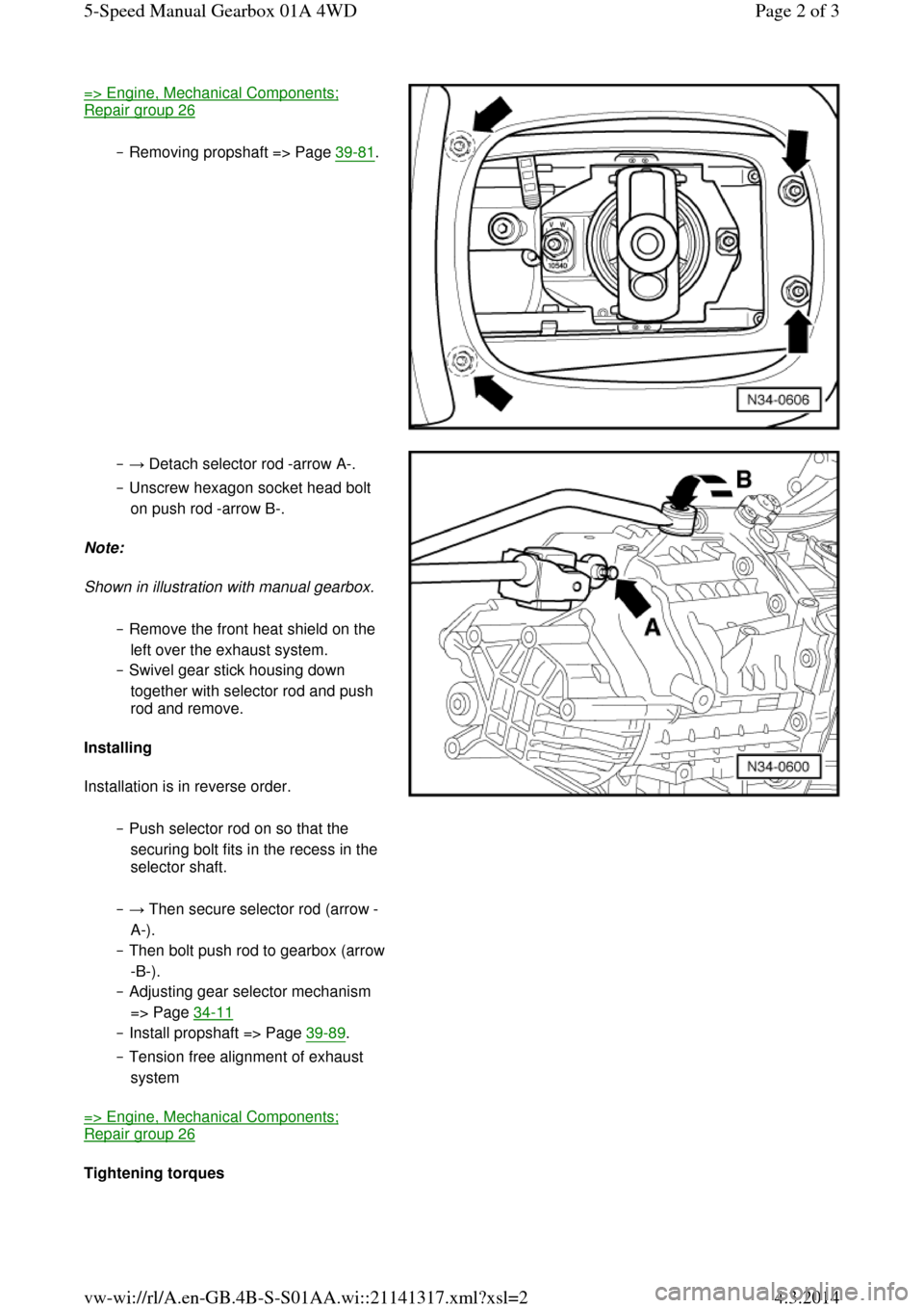
=> Engine, Mechanical Components; Repair group 26
‒ Removing propshaft => Page 39-81. ‒ → Detach selector rod -arrow A-.
‒ Unscrew hexagon socket head bolt
on push rod -arrow B-.
Note:
Shown in illustration with manual gearbox.
‒ Remove the front heat shield on the
left over the exhaust system.
‒ Swivel gear stick housing down
together with selector rod and push
rod and remove.
Installing
Installation is in reverse order.
‒ Push selector rod on so that the
securing bolt fits in the recess in the
selector shaft. ‒ → Then secure selector rod (arrow -
A-).
‒ Then bolt push rod to gearbox (arrow -B-).
‒ Adjusting gear selector mechanism
=> Page 34-11
‒ Install propshaft => Page 39-89.
‒ Tension free alignment of exhaust
system
=> Engine, Mechanical Components; Repair group 26
Tightening torques Page 2 of 35-Speed Manual Gearbox 01A 4WD4.3.2014vw-wi://rl/A.en-GB.4B-S-S01AA.wi::21141317.xml?xsl=2
Page 42 of 71
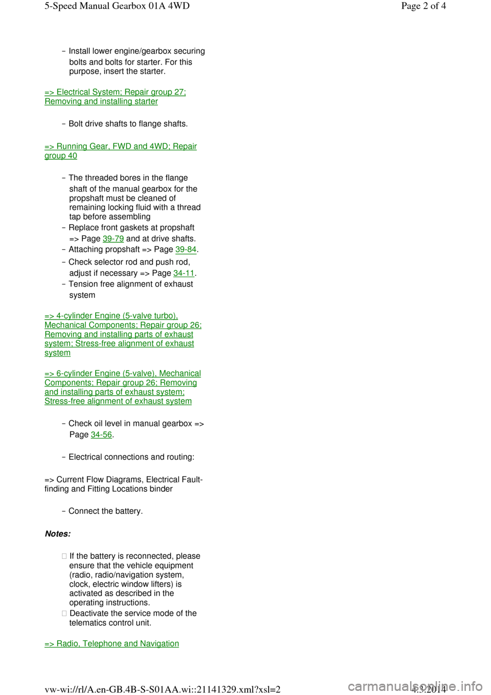
‒ Install lower engine/gearbox securing bolts and bolts for starter. For this
purpose, insert the starter.
=> Electrical System; Repair group 27; Removing and installing starter
‒ Bolt drive shafts to flange shafts.
=> Running Gear, FWD and 4WD; Repair group 40
‒ The threaded bores in the flange
shaft of the manual gearbox for the
propshaft must be cleaned of
remaining locking fluid with a thread
tap before assembling
‒ Replace front gaskets at propshaft
=> Page 39-79 and at drive shafts.
‒ Attaching propshaft => Page 39-84.
‒ Check selector rod and push rod,
adjust if necessary => Page 34-11.
‒ Tension free alignment of exhaust
system
=> 4-cylinder Engine (5-valve turbo), Mechanical Components; Repair group 26; Removing and installing parts of exhaust system; Stress-free alignment of exhaust system
=> 6-cylinder Engine (5-valve), Mechanical Components; Repair group 26; Removing and installing parts of exhaust system; Stress-free alignment of exhaust system
‒ Check oil level in manual gearbox => Page 34-56.
‒ Electrical connections and routing:
=> Current Flow Diagrams, Electrical Fault-
finding and Fitting Locations binder
‒ Connect the battery.
Notes:
◆ If the battery is reconnected, please
ensure that the vehicle equipment
(radio, radio/navigation system,
clock, electric window lifters) is
activated as described in the
operating instructions.
◆ Deactivate the service mode of the
telematics control unit.
=> Radio, Telephone and Navigation Page 2 of 45-Speed Manual Gearbox 01A 4WD4.3.2014vw-wi://rl/A.en-GB.4B-S-S01AA.wi::21141329.xml?xsl=2
Page 46 of 71
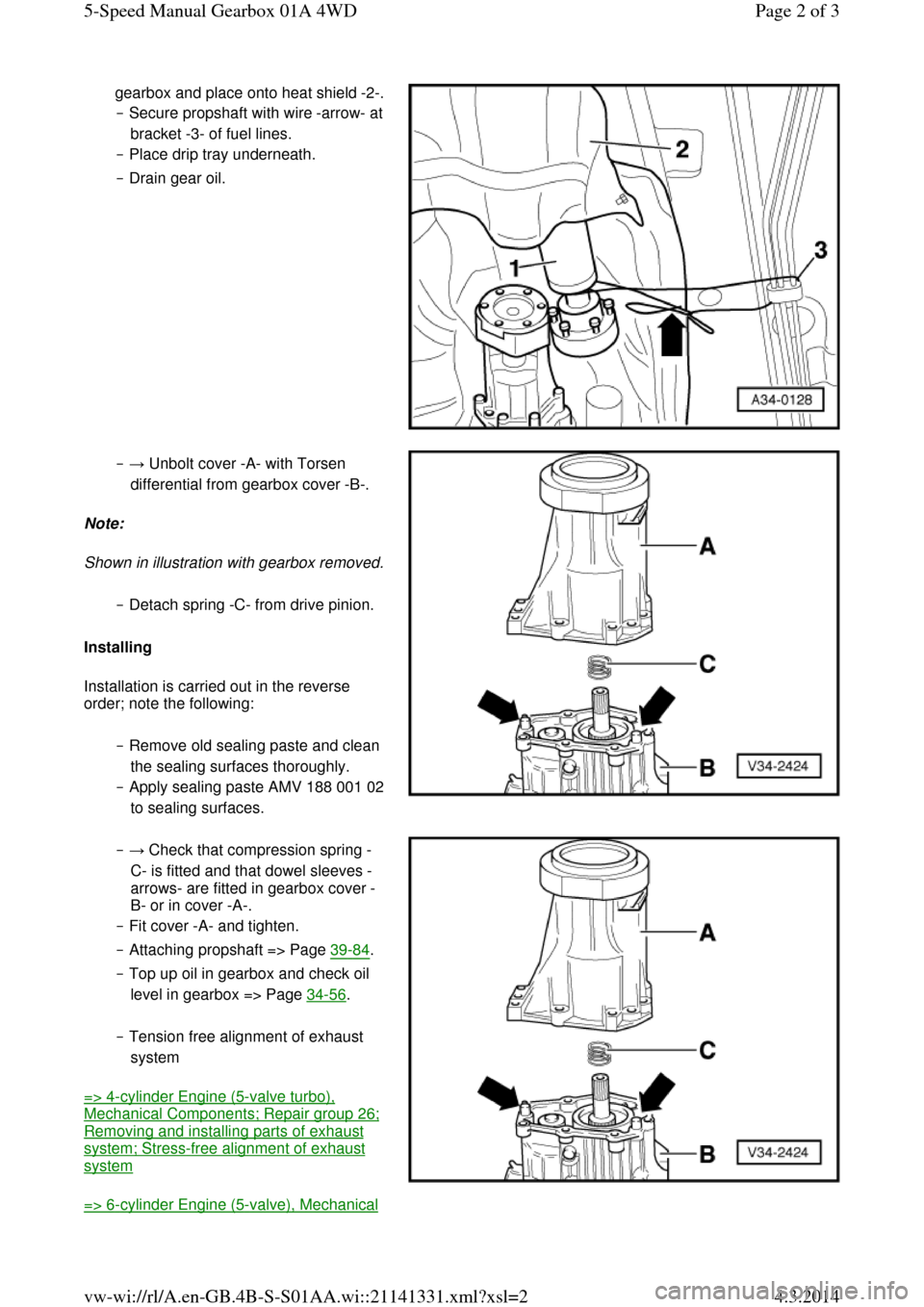
gearbox and place onto heat shield -2-. ‒ Secure propshaft with wire -arrow- at bracket -3- of fuel lines.
‒ Place drip tray underneath.
‒ Drain gear oil. ‒ → Unbolt cover -A- with Torsen
differential from gearbox cover -B-.
Note:
Shown in illustration with gearbox removed. ‒ Detach spring -C- from drive pinion.
Installing
Installation is carried out in the reverse
order; note the following:
‒ Remove old sealing paste and clean
the sealing surfaces thoroughly.
‒ Apply sealing paste AMV 188 001 02 to sealing surfaces. ‒ → Check that compression spring -
C- is fitted and that dowel sleeves -
arrows- are fitted in gearbox cover -
B- or in cover -A-.
‒ Fit cover -A- and tighten.
‒ Attaching propshaft => Page 39-84.
‒ Top up oil in gearbox and check oil
level in gearbox => Page 34-56.
‒ Tension free alignment of exhaust
system
=> 4-cylinder Engine (5-valve turbo), Mechanical Components; Repair group 26; Removing and installing parts of exhaust system; Stress-free alignment of exhaust system
=> 6-cylinder Engine (5-valve), Mechanical Page 2 of 35-Speed Manual Gearbox 01A 4WD4.3.2014vw-wi://rl/A.en-GB.4B-S-S01AA.wi::21141331.xml?xsl=2
Page 58 of 71

◆ V.A.G 1331 Torque wrench
◆ Sealant AMV 188 001 02 Notes:
◆ It is not necessary to remove the
differential to remove the above-
mentioned components => Page 34-74.
◆ Removal is only necessary when
adjustments have to be carried out
=> adjustment overview, Page 39-45.
Removing
‒ Place drip tray V.A.G 1306
underneath the gearbox.
‒ Drain gearbox oil using socket
attachment 3357.
‒ → Secure gearbox in assembly
stand VW 540. Page 2 of 115-Speed Manual Gearbox 01A 4WD4.3.2014vw-wi://rl/A.en-GB.4B-S-S01AA.wi::21141337.xml?xsl=2
Page 69 of 71
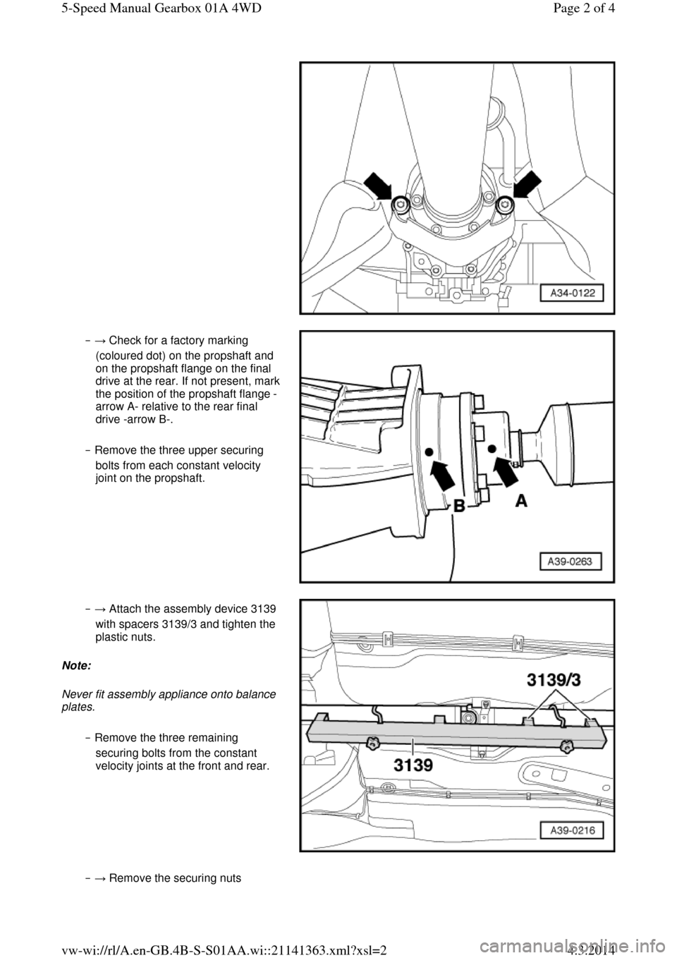
‒ → Check for a factory marking
(coloured dot) on the propshaft and
on the propshaft flange on the final drive at the rear. If not present, mark the position of the propshaft flange -
arrow A- relative to the rear final
drive -arrow B-.
‒ Remove the three upper securing
bolts from each constant velocity
joint on the propshaft. ‒ → Attach the assembly device 3139
with spacers 3139/3 and tighten the
plastic nuts.
Note:
Never fit assembly appliance onto balance plates.
‒ Remove the three remaining
securing bolts from the constant
velocity joints at the front and rear. ‒ → Remove the securing nuts Page 2 of 45-Speed Manual Gearbox 01A 4WD4.3.2014vw-wi://rl/A.en-GB.4B-S-S01AA.wi::21141363.xml?xsl=2