torque AUDI A6 2000 C5 / 2.G Changing Clutch 5Speed Manual Gearbox
[x] Cancel search | Manufacturer: AUDI, Model Year: 2000, Model line: A6, Model: AUDI A6 2000 C5 / 2.GPages: 71, PDF Size: 1.82 MB
Page 27 of 71
Servicing clutch Servicing clutch Special tools and workshop equipment
required
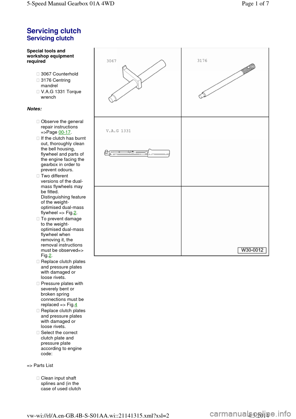
◆ 3067 Counterhold
◆ 3176 Centring
mandrel
◆ V.A.G 1331 Torque
wrench
Notes:
◆ Observe the general
repair instructions
=>Page 00-17.
◆ If the clutch has burnt out, thoroughly clean
the bell housing,
flywheel and parts of
the engine facing the
gearbox in order to
prevent odours.
◆ Two different
versions of the dual-
mass flywheels may
be fitted. Distinguishing feature of the weight-
optimised dual-mass
flywheel => Fig.2.
◆ To prevent damage
to the weight-
optimised dual-mass
flywheel when
removing it, the
removal instructions
must be observed=>
Fig.2.
◆ Replace clutch plates and pressure plates
with damaged or
loose rivets.
◆ Pressure plates with
severely bent or
broken spring
connections must be
replaced => Fig.4
◆ Replace clutch plates and pressure plates
with damaged or
loose rivets.
◆ Select the correct
clutch plate and
pressure plate
according to engine
code:
=> Parts List
◆ Clean input shaft
splines and (in the
case of used clutch Page 1 of 75-Speed Manual Gearbox 01A 4WD4.3.2014vw-wi://rl/A.en-GB.4B-S-S01AA.wi::21141315.xml?xsl=2
Page 31 of 71
installing:
=> Relevant
engine
workshop
manual,
Mechanical
components;
Repair group
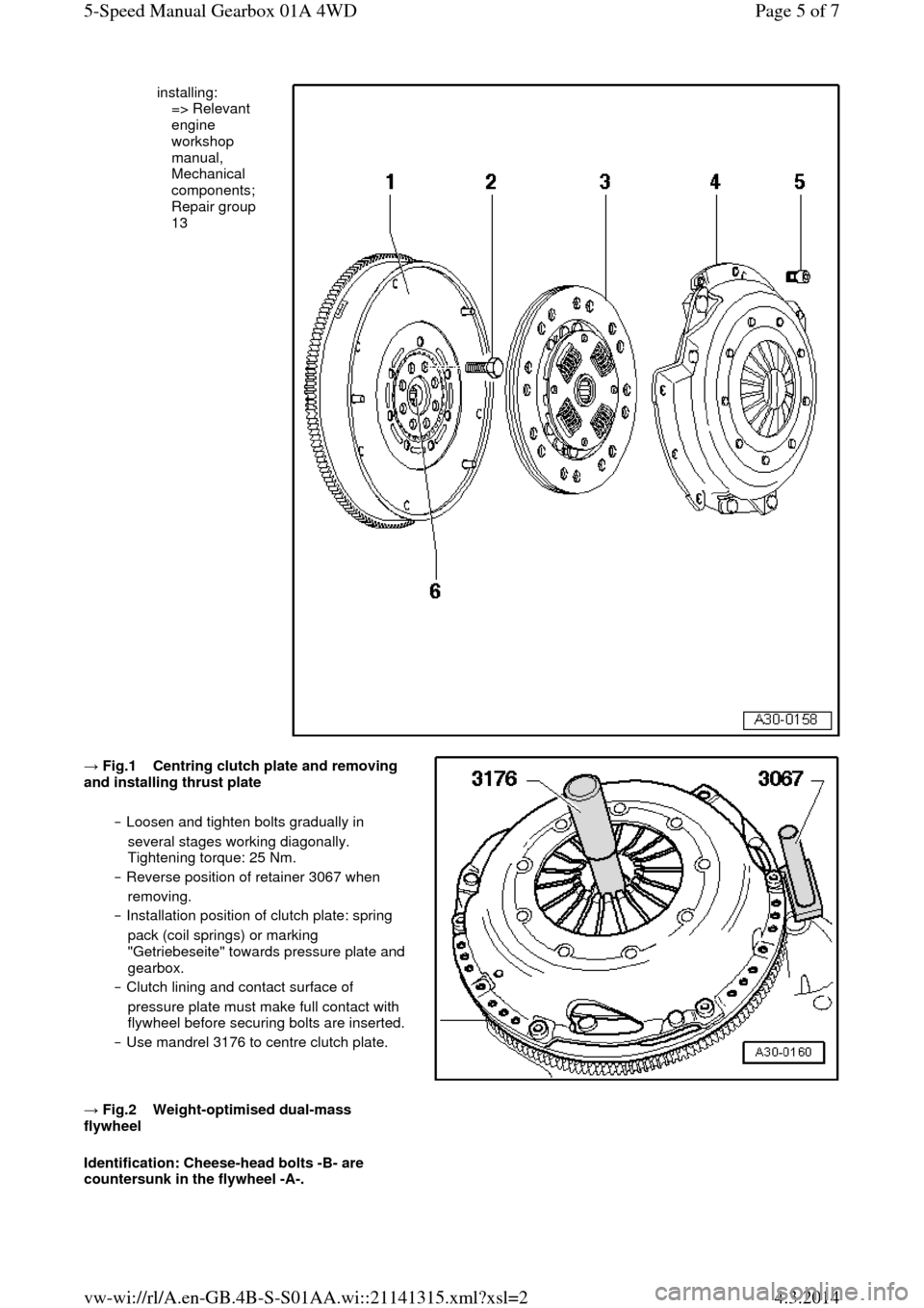
13 → Fig.1 Centring clutch plate and removing and installing thrust plate
‒ Loosen and tighten bolts gradually in
several stages working diagonally.
Tightening torque: 25 Nm.
‒ Reverse position of retainer 3067 when
removing.
‒ Installation position of clutch plate: spring
pack (coil springs) or marking
"Getriebeseite" towards pressure plate and
gearbox.
‒ Clutch lining and contact surface of
pressure plate must make full contact with
flywheel before securing bolts are inserted. ‒ Use mandrel 3176 to centre clutch plate.
→ Fig.2 Weight-optimised dual-mass flywheel
Identification: Cheese-head bolts -B- are
countersunk in the flywheel -A-. Page 5 of 75-Speed Manual Gearbox 01A 4WD4.3.2014vw-wi://rl/A.en-GB.4B-S-S01AA.wi::21141315.xml?xsl=2
Page 35 of 71
=> Engine, Mechanical Components; Repair group 26
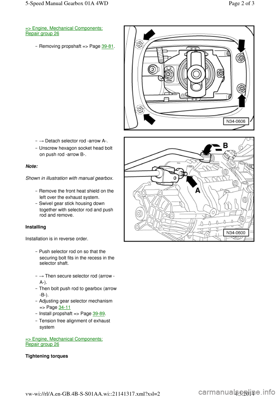
‒ Removing propshaft => Page 39-81. ‒ → Detach selector rod -arrow A-.
‒ Unscrew hexagon socket head bolt
on push rod -arrow B-.
Note:
Shown in illustration with manual gearbox.
‒ Remove the front heat shield on the
left over the exhaust system.
‒ Swivel gear stick housing down
together with selector rod and push
rod and remove.
Installing
Installation is in reverse order.
‒ Push selector rod on so that the
securing bolt fits in the recess in the
selector shaft. ‒ → Then secure selector rod (arrow -
A-).
‒ Then bolt push rod to gearbox (arrow -B-).
‒ Adjusting gear selector mechanism
=> Page 34-11
‒ Install propshaft => Page 39-89.
‒ Tension free alignment of exhaust
system
=> Engine, Mechanical Components; Repair group 26
Tightening torques Page 2 of 35-Speed Manual Gearbox 01A 4WD4.3.2014vw-wi://rl/A.en-GB.4B-S-S01AA.wi::21141317.xml?xsl=2
Page 43 of 71
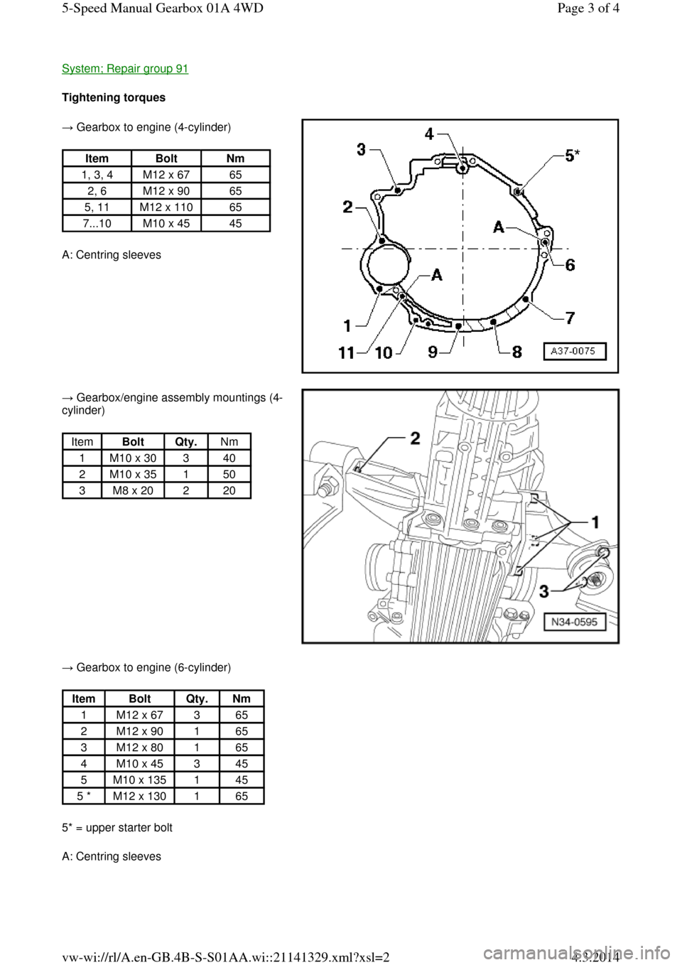
System; Repair group 91 Tightening torques → Gearbox to engine (4-cylinder)
A: Centring sleeves Item Bolt Nm
1, 3, 4 M12 x 67 65
2, 6 M12 x 90 65
5, 11 M12 x 110 65
7...10 M10 x 45 45 → Gearbox/engine assembly mountings (4-
cylinder)
Item Bolt Qty. Nm
1 M10 x 30 3 40
2 M10 x 35 1 50
3 M8 x 20 2 20 → Gearbox to engine (6-cylinder)
5* = upper starter bolt
A: Centring sleeves Item Bolt Qty. Nm
1 M12 x 67 3 65
2 M12 x 90 1 65
3 M12 x 80 1 65
4 M10 x 45 3 45
5 M10 x 135 1 45
5 * M12 x 130 1 65 Page 3 of 45-Speed Manual Gearbox 01A 4WD4.3.2014vw-wi://rl/A.en-GB.4B-S-S01AA.wi::21141329.xml?xsl=2
Page 47 of 71
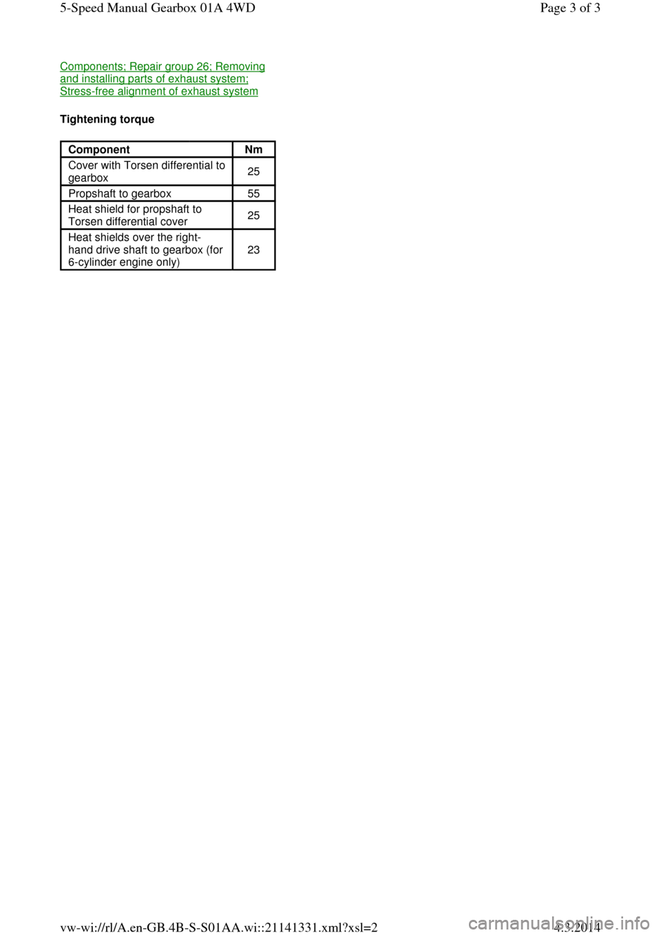
Components; Repair group 26; Removing and installing parts of exhaust system; Stress-free alignment of exhaust system
Tightening torque
Component Nm
Cover with Torsen differential to
gearbox 25
Propshaft to gearbox 55
Heat shield for propshaft to
Torsen differential cover 25
Heat shields over the right-
hand drive shaft to gearbox (for
6-cylinder engine only) 23 Page 3 of 35-Speed Manual Gearbox 01A 4WD4.3.2014vw-wi://rl/A.en-GB.4B-S-S01AA.wi::21141331.xml?xsl=2
Page 58 of 71

◆ V.A.G 1331 Torque wrench
◆ Sealant AMV 188 001 02 Notes:
◆ It is not necessary to remove the
differential to remove the above-
mentioned components => Page 34-74.
◆ Removal is only necessary when
adjustments have to be carried out
=> adjustment overview, Page 39-45.
Removing
‒ Place drip tray V.A.G 1306
underneath the gearbox.
‒ Drain gearbox oil using socket
attachment 3357.
‒ → Secure gearbox in assembly
stand VW 540. Page 2 of 115-Speed Manual Gearbox 01A 4WD4.3.2014vw-wi://rl/A.en-GB.4B-S-S01AA.wi::21141337.xml?xsl=2
Page 71 of 71
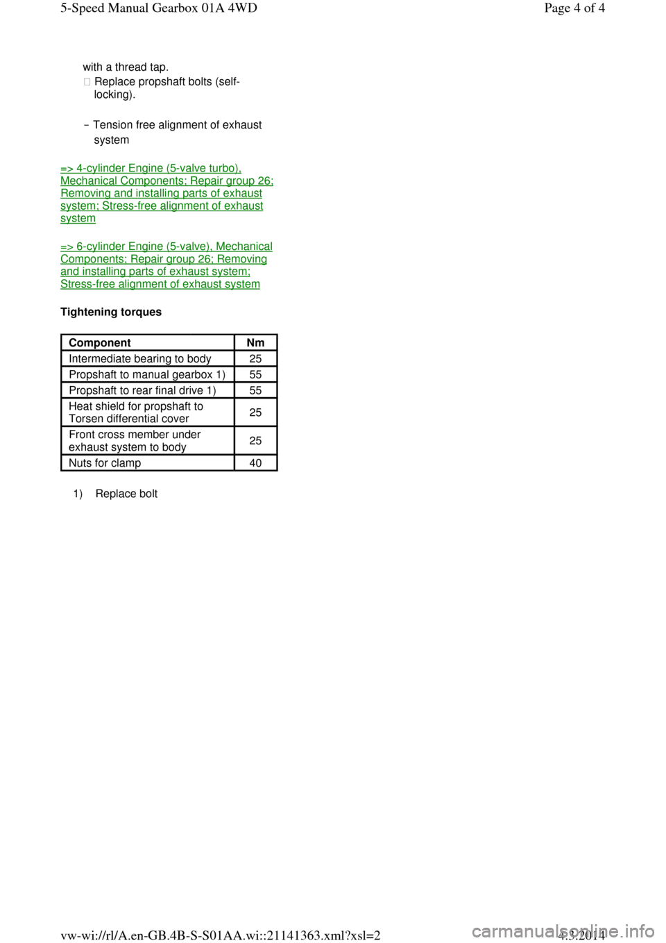
with a thread tap.
◆ Replace propshaft bolts (self-
locking).
‒ Tension free alignment of exhaust
system
=> 4-cylinder Engine (5-valve turbo), Mechanical Components; Repair group 26; Removing and installing parts of exhaust system; Stress-free alignment of exhaust system
=> 6-cylinder Engine (5-valve), Mechanical Components; Repair group 26; Removing and installing parts of exhaust system; Stress-free alignment of exhaust system
Tightening torques
1) Replace bolt Component Nm
Intermediate bearing to body 25
Propshaft to manual gearbox 1) 55
Propshaft to rear final drive 1) 55
Heat shield for propshaft to
Torsen differential cover 25
Front cross member under
exhaust system to body 25
Nuts for clamp 40 Page 4 of 45-Speed Manual Gearbox 01A 4WD4.3.2014vw-wi://rl/A.en-GB.4B-S-S01AA.wi::21141363.xml?xsl=2