ad blue AUDI A6 2015 Owners Manual
[x] Cancel search | Manufacturer: AUDI, Model Year: 2015, Model line: A6, Model: AUDI A6 2015Pages: 314, PDF Size: 77.57 MB
Page 15 of 314
M N
0 <.J 'SI: ,...., \!) 1.1"1 ,...., 1.1"1 ,....,
Instrument s and warnin g/indic ator ligh ts 13
compartment, stop the engine and let it
cool down. Always exercise extreme cau
t ion when working under the hood
c>page222.
Overview
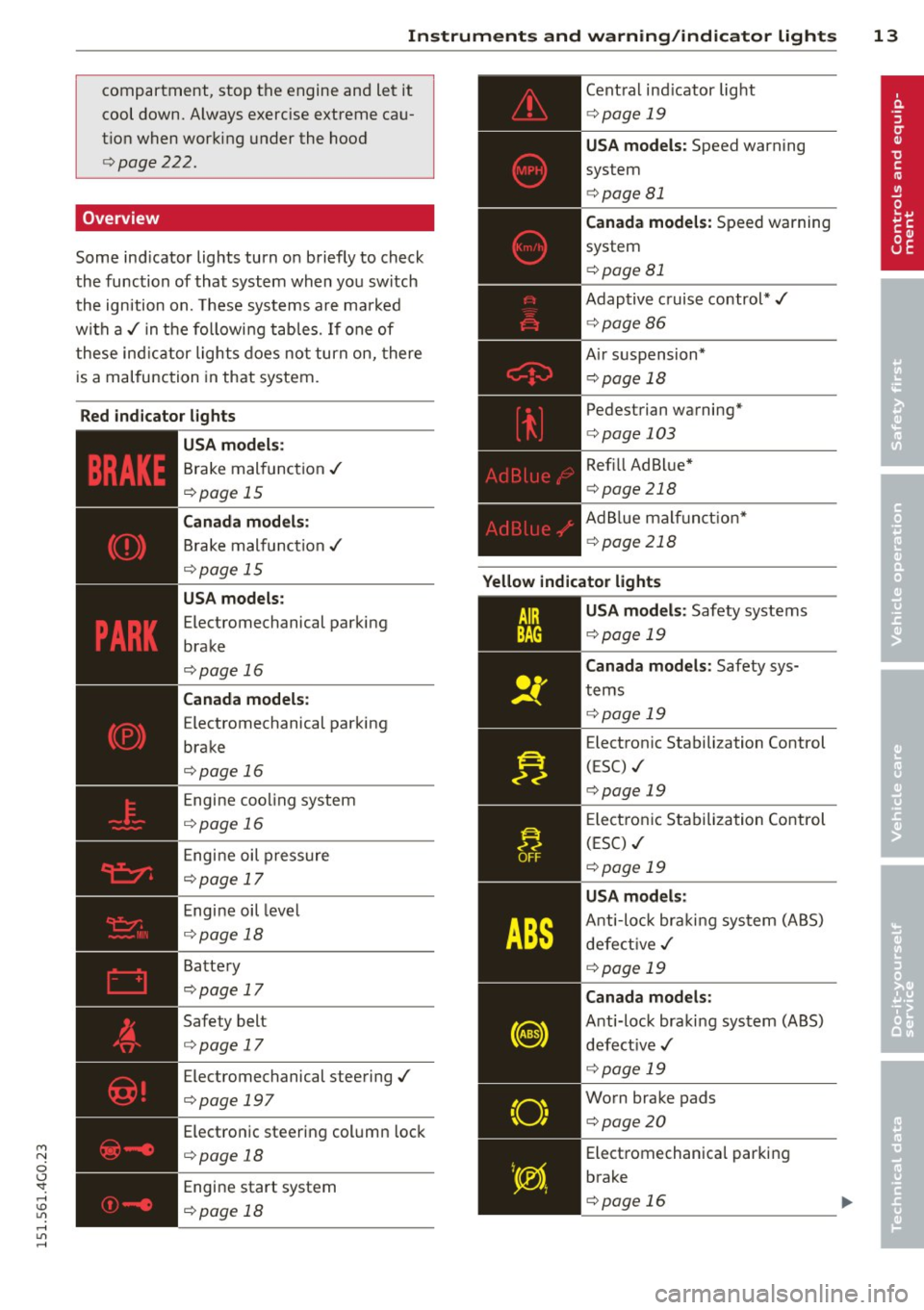
Some ind icator lights turn on briefly to check
the function of that system when you switch
the ignition on. These systems are marked
w ith a,/ in the followi ng tables.
If one of
these indicator lights does no t turn on, there
is a malfunction in that system.
Red ind ic a tor l ights
-------------
U SA model s:
Brake malfunction ,/
c>page 15
Canada m odel s:
Brake malfunction ,/
c>page 15
USA models:
Electromechanical parking
brake
c>page 16
Canada m odel s:
Electromechanical parking
brake
c>page 16
Engine cooling system
c>page 16
Engine oil pressure
c>page 17
Engine oil level
c> page 18
Battery
c>page 17
Safety belt
c>page 17
Electromechanical steering,/
c>page 197
Electronic steering column lock
c>page 18
Engine start system
c>page 18
Central ind icator light
c> page 19
USA models: Speed warning
system
c> page 81
Canada mod els : Speed warning
system
c> page 81
Adaptive c ruise control*,/
c> page86
Air suspension*
c> page 18
Pedestrian warning*
c>page 103
Refill Ad Blue*
c> page 218
AdBlue malf unct ion*
c> page 218
Yellow indicator li ght s
"O~ I I \; ,,
-------------
USA models : Safety systems
c>page 19
Canada models : Safety sys
tems
c> page 19
Electron ic Stabilization Control
(ESC) ./
c>page 19
Electronic Stabilization Control
(ESC) ,/
c>page 19
USA model s:
Anti-loc k braki ng system (ABS)
defect ive ,/
c>page 19
Canad a mod els :
Anti-lock braking system (ABS)
defect ive ,/
c>page 19
Worn brake pads
c>page20
Electromechanica l parking
brake
c>page 16
Page 16 of 314
14 Instruments and warning/indicator lights
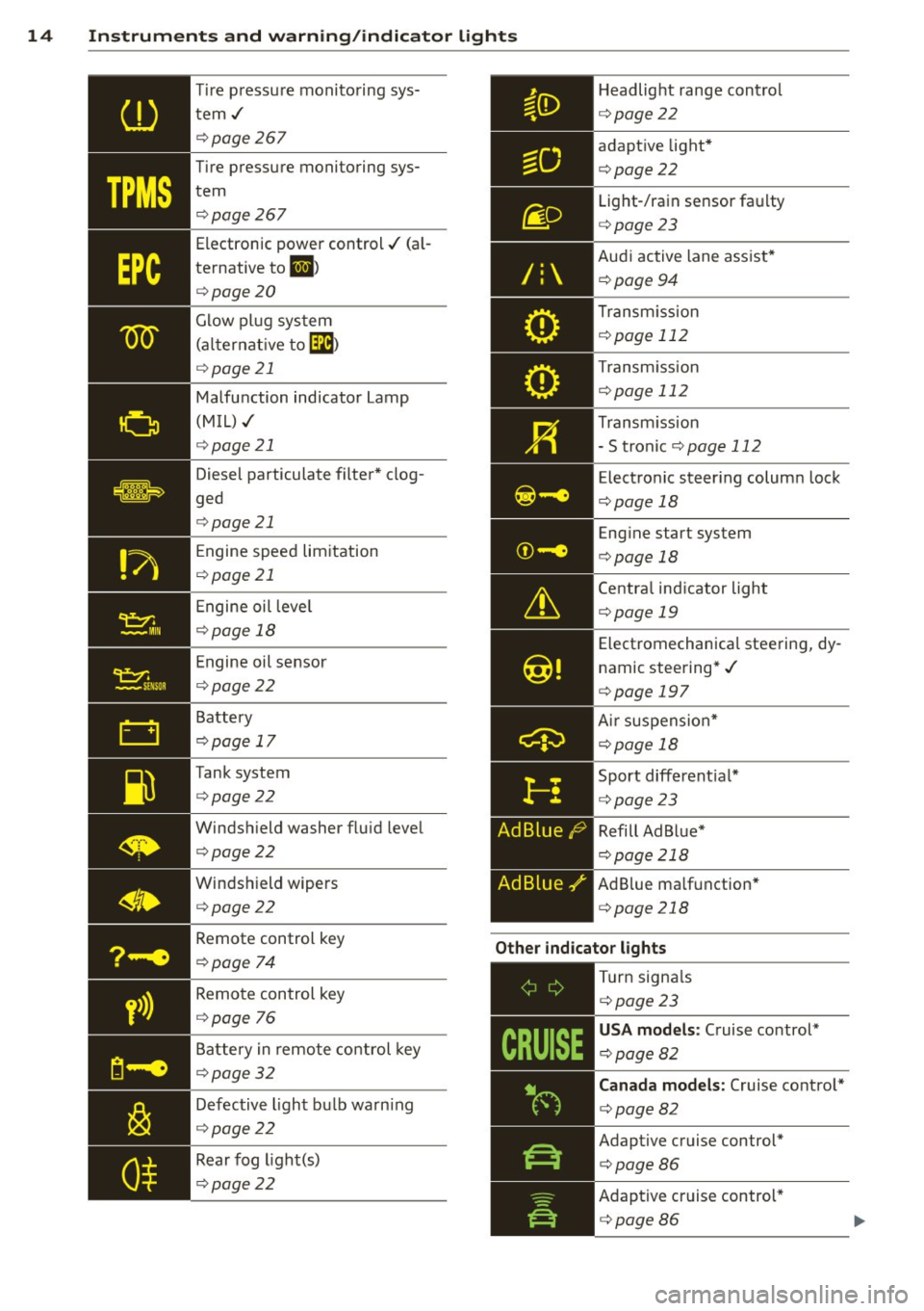
Tire pressure monitoring sys
tem./ ¢ page267
Tire pressure monitoring sys
tem q page 267
Electronic power control./ (a l
ternative to
1,1 )
qpage 20
Glow plug system
(alternat ive to
Ga)
qpage 21
Malfunction indicator Lamp
(MIL) ./
¢ page 21
Diesel particulate filter* clog
ged
q page 21
Engine speed limitation
q page 21
Engine oil leve l
qpage 18
Engine oil sensor
qpage22
Battery
q page 17
Tank system q page 22
Windshield washer fluid level q page22
Windshield wipers
q page 22
/:
Headlight range control
q page22
adaptive light*
qpage22 Light-/rain sensor faulty
q page23
Audi active lane assist*
¢ page94
Transm ission
¢ page 112
Transm ission
¢ page 112
Transm ission
- S tronic
¢ page 112
Electronic steering column lock
q page 18
Engine start system
q page 18
Central indicator light
qpage 19
Electromechanical steering, dy
namic steering*./
q page 197
Ai r suspension*
¢page 18
Sport different ial*
¢ page 23
Refill Ad Blue*
q page 218
AdBlue ma lfunction*
q page 218
Remote control key
q page 74
Other indicator lights
y>))
Remote control key
q page
76
Battery in remote control key
q page 32
Defective light bulb warn ing
q page 22
Rear fog light(s)
q page22
,-------------
Turn signa ls
¢ page23
USA models: Cruise control*
¢ page82
Canada models: Cruise control*
q page82
Adaptive cruise control*
qpage86
Adaptive cruise control*
q page86
Page 71 of 314
M N
0 <.J 'SI: ,...., \!) 1.1'1 ,...., 1.1'1 ,....,
l
ed or cleared of condensation as quickly as
possib le. The maximum amount of air flows
mainly from the vents be low the windshield.
Recirculation mode switches off. The tempera
ture should be set to approximately 72 °F (22
°() .
The IAUTOI button switches the defroster off.
IQil REAR I Switching rear window heater
on/off
The rear window heater only operates when
the engine is running.
It switches off auto
matica lly after a few minutes, depending on
the outside temperature.
To prevent the rear window heater from
switch ing off automatica lly, press and hold
the
!llill REARI button for more than 2 seconds.
This remains stored until the ignition is
sw itched off.
QJ Adjusting seat heating
Pressing the button switches the seat heating
on at the highest setting ( leve l 3) . The LEDs
indicate the temperature level. To reduce the
temperature, press the button again. To
switch the seat heating off, press the button repeatedly until the LE D turns off .
After 10 minutes, the seat heating automati
cally switches from leve l 3 to level 2.
The seat heating for both outer rear seats * is
adj usted using the buttons in the center con
sole.
Warm and cold 69
Air vents
You can open or close the center and outer
vents in the cockpit and the vents in the rear
center console using the ridged thumbwheels.
The levers adjust the direction of the airflow
from the vents.
The air temperature in the rear can be adjust
ed so that it is warmer or co lder by turning
the knob to the red or blue area.
A WARNING
- Do not use the recirc ulation for extended
periods of time. The windows could fog
up since no fresh a ir can enter the vehi
cle. If the windows fog up, press the air
recirc ulat ion button again immed iately
to switch off the air recirculation func
tion or select defrost.
- Individuals with reduced sensitivity to
pa in or temperature could develop burns
when using the seat heating function . To
red uce the risk of injury, these individu
a ls shou ld not use seat heating.
(D Note
To avoid damage to the heating elements
in the seats, do not kneel on the seats or
place heavy loads on a small area of the
seat.
Page 118 of 314
116 Parking systems
the next to last segment is disp layed . Obsta
cles in the collision area, including those out
side of the vehicle 's path, are shown in red. Do
not continue driving farther forward or in re
verse
q .&. in General information on
page 114, q(f) in General information on
page 114 .
Rear view camera
Introduction
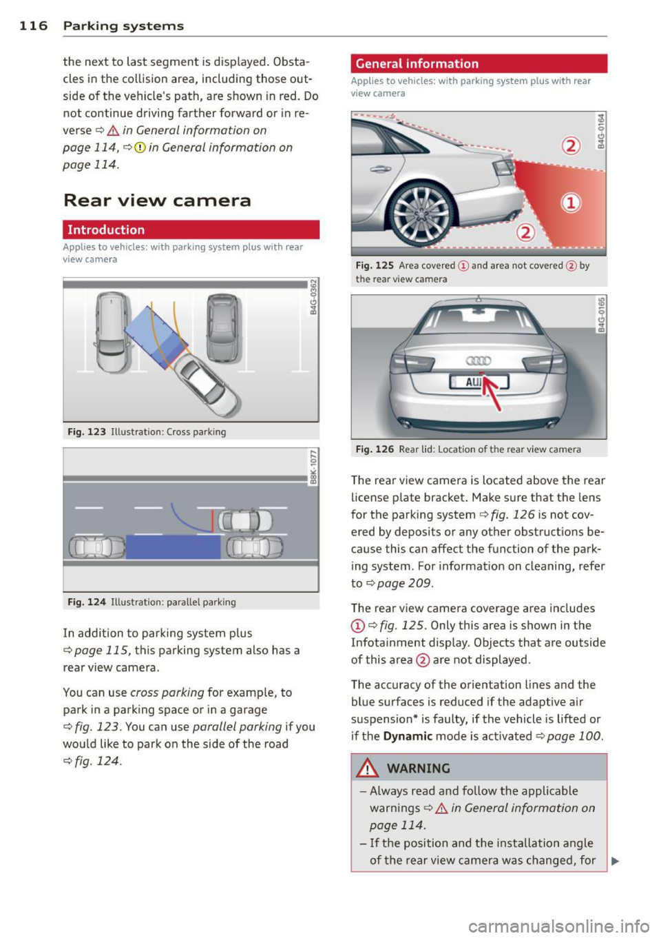
Applies to vehicles: with parking system plus with rear
view camera
Fig. 123 Illustration: Cross parking
F ig. 124 Illustrat ion: paralle l parking
In addition to parking system p lus
q page 115, this parking system also has a
rear view camera .
You can use
cross parking for examp le, to
park in a parking space or in a garage
q fig. 123. You can use parallel parking if you
wou ld like to park on the side of the road
r::;, fig . 124.
General information
Applies to vehicles: with parking system plus with rear
view camera
F ig. 12S Area covered (D a nd area not covered @by
the rear v iew camera
Fig. 1 26 Rear lid: Locat ion of t he rear view camera
T he rea r view camera is located above the rear
license p late bracket . Make s ure that the lens
for the parking system
q fig. 126 is not cov
ered by deposits or any other obstruct ions be
cause this can affect the function of the park
ing system . For informat ion on cleaning, refer
to
q page 209.
The rear view camera coverage area includes
(D q fig. 125. Only this area is shown in the
Infotainment display . Objects that are outside
of this area @are not displayed.
The accuracy of the orientation lines and the
blue surfaces is reduced if the adapt ive air
suspension* is faulty, if the vehicle is lifted or if the
Dynamic mode is activated r::;, page 100 .
A WARNING
-
-Always read a nd follow the applicable
warn ings
r::;, .&. i n Ge neral information on
p age 114.
- If the position and the installation angle
-
of the rear view camer a was changed, for ~
Page 120 of 314
118 Parking systems
Cross parking
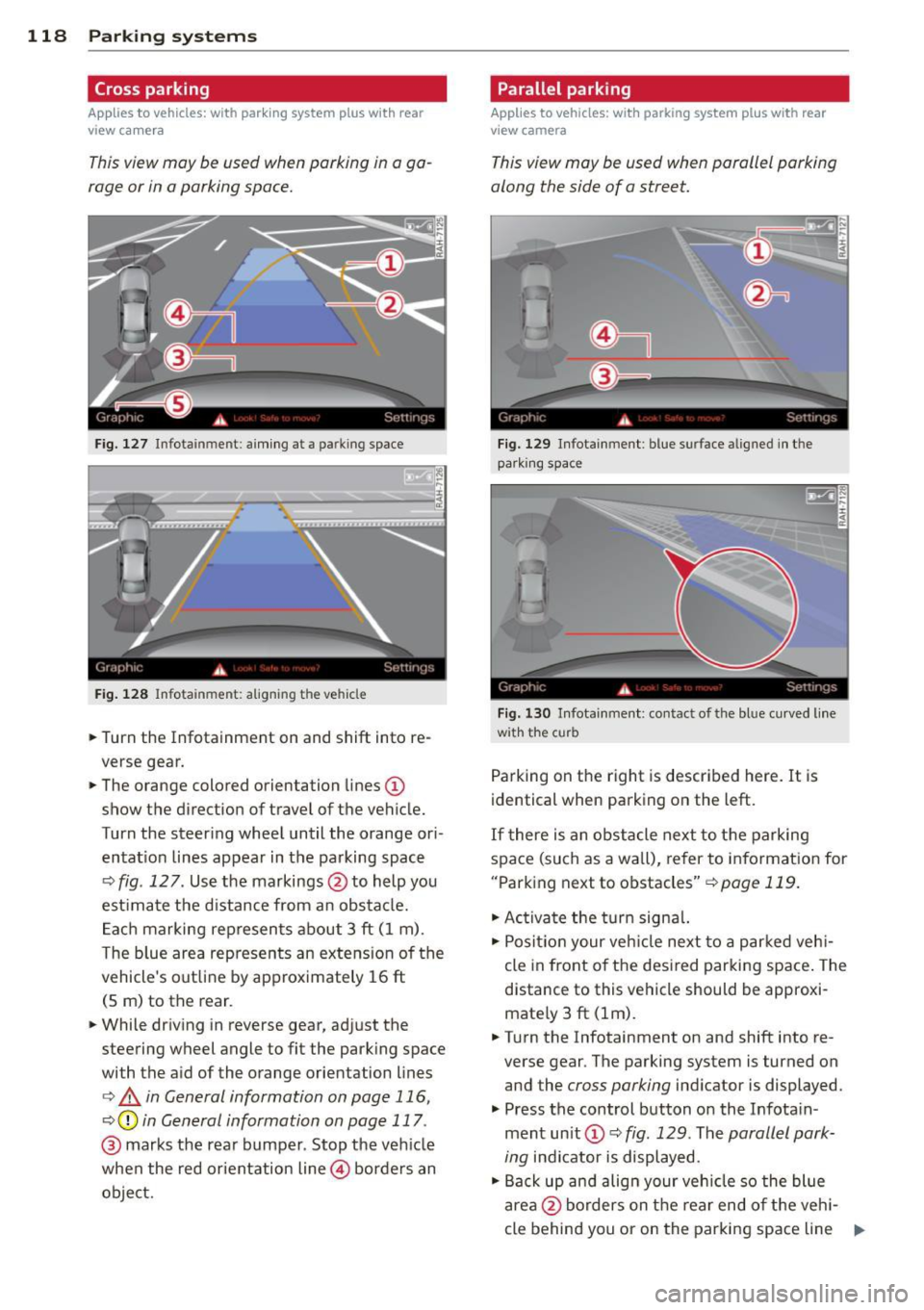
Applies to vehicles: with park ing system p lus w it h rear
view ca mera
This view may be used when parking in a ga
rage or in a parking space.
F ig. 127 Infotainment: aim ing at a parking space
Fig. 128 Infotainment : aligning the ve hicle
... Turn the Infotainment on and shift into re
verse gear.
... The orange colored orientation lines
(D
show the direction of travel of the vehicle.
Turn the steering wheel until the orange ori
entat ion lines appear in the parking space
¢ fig. 12 7. Use the markings @to help you
est imate the distance from an obstacle.
Each marking represents about 3 ft (1 m).
The blue area represents an extens ion of the
vehicle's out line by approximately 16 ft
(5 m) to the rear.
... While driving in reverse gear, adjust the
steering wheel angle to fit the parking space
with the aid of the orange orientation lines
¢ & in General information on page 116,
¢ @ in General information on page 117 .
@ marks the rear bumper . Stop the vehicle
when the red orientation line@ borders an
object.
Parallel parking
Applies to vehicles : wit h parking system pl us with rear
v iew camera
This view may be used when parallel parking
along the side of a street.
Fig . 129 Infotainment : blue surface aligned in the
par king space
Fig. 130 Infotainme nt: contact of the blue curved lin e
w ith the curb
Parking on the right is described here. It is
identical when parking on the left.
If there is an obstacle next to the parking
space (such as a wall), refer to information for
"Parking next to obstacles"¢
page 119.
"'Activate the turn signal.
"'P osit ion your veh icle next to a parked vehi
cle in front of the desired parking space. The
distance to this vehicle should be approxi
mate ly 3 ft (lm) .
... Turn the Infotainment on and shift into re
verse gear. The parking system is turned on
and the
cross parking indicator is displayed.
"' Press the control button on the Infota in
ment unit (!) ¢
fig. 129 . The parallel park
ing
indicator is displayed.
"' Back up and align your vehicle so the blue
area @borders on the rear end of the vehi-
cle behind you or on the parking space line ..,.
Page 121 of 314
M N
0 I.J "". rl I.O
"' rl
"' rl
r::> & in General information on page 116,
r::>(D in General information on page 117.
The blue area represents an extens ion of the
vehicle's outline by approximately 16 ft
(5 m) to the rear . The long side of the blue
area should be on the curb . The entire blue
area must fit into the parking space.
• With the veh icle stopped, turn the steering
wheel to the right as far as it w ill go.
• Back in to the park ing space u ntil the b lue
curve
r::> fig . 130 touches the curb r::> & in
General information on page 116,
r::> (D in
General information on page 117 .
Stop the
vehicle.
• With the veh icle stopped , turn the steer ing
whee l to the left as far as it will go .
• Continue to back into the parking space un
t il the vehicle is parked pa rallel to the cu rb
r::> & in General information on page 116,
r::> (D in General information on page 117.
@ marks the rear bumper . Stop the veh icle,
at the latest, when the red orientation line
@ borders an object. Keep an eye on the
front of your vehicle whi le do ing th is .
Pa rking next to obstacles
If there is an obstacle (s uc h a s a wall) next to
the par king space, position the veh icle so
there is more space o n that s ide. Position the
l ong side of the blue s urface so that there is
sufficient space from the obstacle . The sur
face must not be to uch ing . You will also need
to star t turning the steer ing wheel much ear
lier . The blue curve
r::> fig . 130 must not touch
the obstacle and should have sufficient room.
(D Note
Remember to maintain sufficient clear
ance from the curb to avoid damag ing the
wheel rims .
(D Tips
The left or right orientation lines and sur
faces will be displayed, depend ing on the
turn sig na l being used.
P arking systems 119
Peripheral cameras
Introduction
Applies to vehicles: with parking system plus with periph
eral cameras
In add ition to parking system plus
¢ page 115, this parking system conta ins pe
ripheral cameras . Depending on the vehicle
equipment , you are ass isted by vario us views
su ch a s p eriphera l view, corne r views a t the
fron t and rear of the veh icle, and views di rect
ly in front of or behind t he vehicle .
General information
Applies to vehicles: with parking system plus with periph
eral cameras
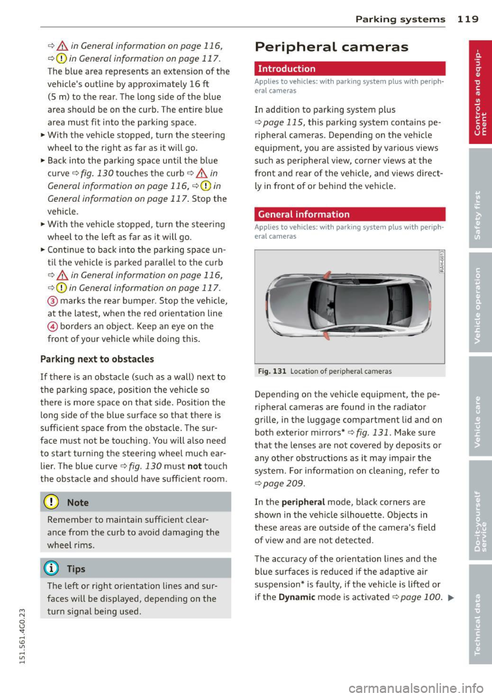
F ig . 1 31 Locat io n of per ip hera l ca meras
Depending on the vehicle equipment, the pe
ripheral cameras are found in the radiator
grille, in the luggage compartment lid and on
both exterior m irrors*
¢ fig. 131 . Make su re
that the lenses a re not covered by depos its o r
any other obstr uctions as it may impa ir t he
system. For info rmat io n on clean ing, refe r to
¢ page 209.
In the peripheral mode , b lack corners are
shown in the ve hicle silhouette . Objects in
these a reas a re outside of the came ra's field
of view and are not detec ted .
The accuracy of the orientation lines and the
bl ue surfaces is reduced if the adaptive a ir
suspension* is faulty, if the vehicle is l ifted or
if t he
D ynamic mode is activa ted ¢ page 100 . ..,.
Page 125 of 314
M N
0 I.J "". rl I.O
"' rl
"' rl
Parallel parking
Applies to vehicles: with parking system plus and rear
mode
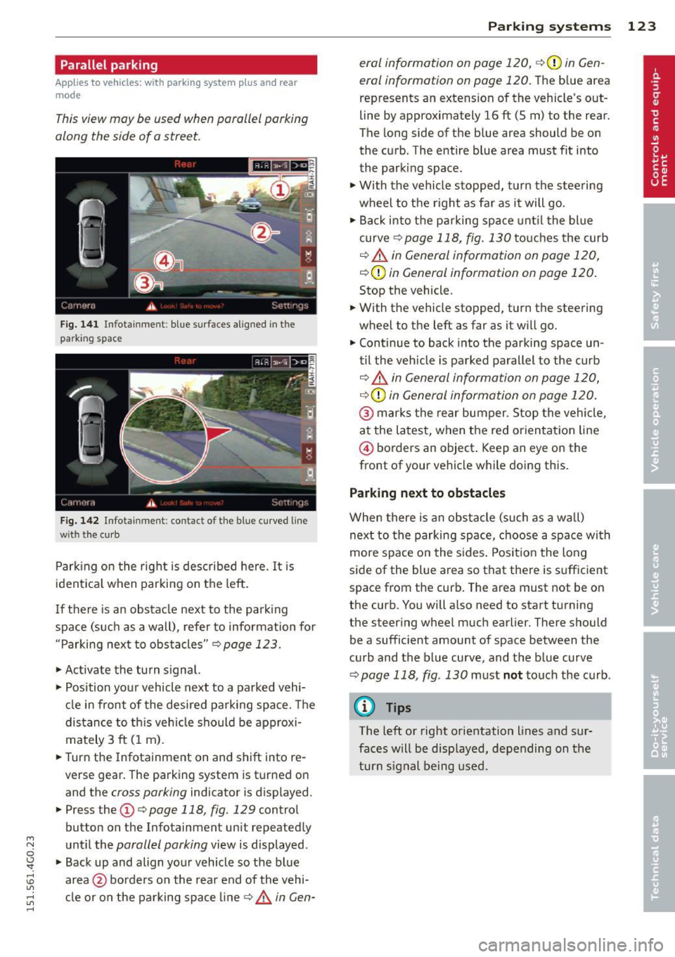
This view may be used when parallel parking
along the side of a street.
Fig. 1 41 Infotainment: blue su rfaces aligned in the
parking space
F ig. 1 42 Infota inmen t: contact of the blue curved line
with th e curb
Park ing on the right is described he re. It is
ident ica l when parking on the left.
I f there is an obstacle next to the park ing
space (such as a wall), refer to information for
"Parking next to obstacles"
c::> page 123.
• Activate the turn s ignal.
• Position your vehicle next to a parked vehi
cle in front of the desired parking space . T he
distance to th is vehicle should be approxi
mately 3 ft (1 m).
• Turn the Infotainment on and shift into re
verse gear. The parking system is turned on
and the
cross parking indicator is displayed.
• Press the
CD c::> page 118 , fig . 129 control
button on the Infotainmen t unit repeatedly
unt il the
parallel parking view is displayed.
• Backup and align your vehicle so the blue
area @borders on the rear end of the vehi
cle or on the pa rking space line
c::> .&, in Gen-
P arking systems 123
era/ information on page 120 , c::>(D in Gen
eral information on page 120.
The b lue area
represents an extens ion of the vehicle 's o ut
line by approximately 16 ft (5 m) to the rear.
The long side of the blue area should be on
the curb . The entire blue area must fit into
the park ing space .
• With the vehicle stopped, turn the stee ring
wheel to the right as fa r as it will go.
• Back i nto the parking space unt il the blue
curve
c::> page 118 , fig. 130 to uches the cu rb
c::> .&. in General information on page 120,
c::>(D in General information on page 120.
Stop the vehicle .
• With the vehicle stopped, turn the steering
wheel to the left as far as it will go.
• Continue to back into the parking space un
til the veh icle is pa rked parallel to the curb
c::> &. in General information on page 120,
c::> (D in General information on page 120.
@ mar ks the rear bumper. Stop the vehicle ,
a t the la test, when the red orien tat ion line
@ borders an object . Keep an eye on the
front of your ve hicle while doing this.
Parking next to obstacles
When there is an obs tacle (su ch as a wall)
next to the parking space, c hoose a spa ce wi th
more spa ce on the s ides . Posit io n the long
side of the blue area so that there is su fficient
space from the curb. The area must not be on
the curb. You will also need to start turning
the steering wheel much earlier . There should
be a sufficient amount of space between the
cu rb and the blue curve, and the blue curve
c::> page 118, fig . 130 must not touch the curb .
(D Tips
The left or right orientation lines and sur
faces will be disp layed, depending on the
turn s ignal being used .
Page 127 of 314

M N
0 <.J 'SI: ,...., \!) 1.1'1 ,...., 1.1'1 ,....,
Error messages
Applies to vehicles: with parking system plus/rear view
camera/per ipheral cameras
There is an e rror in the system if the LED in
the
p, qA button is blinking and you hear a con
tinuous alarm for a few seconds afte r switch
ing on the parking system or when the park
ing system is already activated. If the error is
not corrected before you switch off the igni
tion, the LED in the
Pw.6. button will blink the
next time you switch on the parking system by
shifting into reverse.
Parking system plus
If a sensor is faulty, the~ symbol will appear
in front of/behind the vehicle in the Infotain
ment display. If a rear sensor is fau lty, only
obstacles that are in areas @ and @ are
shown ¢
page 115, fig. 120. If a front sensor
i s faulty, only obstacles that are in areas ©
and @are shown .
Peripheral cameras*
There is also a system error if:
- the
'(:8:)• • symbol appears in the display and
the corresponding display area is shown in
blue. The camera is not working in this area.
- all segments around the vehicles are red or
if no segments are displayed.
Drive to your authorized Aud i dea ler o r au
thorized repair fac ility immediately to have
the ma lfunction corrected.
Trailer hitch
Appl ies to vehicles: with parking system plus/rear view
camera/per ipheral cameras and trailer hitch
For vehicles using the tra iler socket, the park
ing system rear senso rs do not turn on when
you shift into reverse gear or when yo u press
the P
01A button. This results in the following re
strictions:
Parking system plus*
There is no distance wa rning for the rear. The
front sensors rema in activated. The visual dis
play switches to the traile r tow ing mode.
Parking systems 125
Parking system plus and rear view
camera* /Peripheral cameras*
There is no distance warning for the rear. The
front sensors remain activated. The visual dis
play sw itches to the trailer towing mode. The
rear view camera image will not show the ori
entation lines and the blue surfaces .
{D Tips
Trailer hitches that are not installed at the
factory may cause the park ing system to
malfunction or they may restr ict its func
tion.
Page 220 of 314
218 Fuel supply and filling your fuel tank
@ Tips
-Running your engine while refuelling
may cause vapors to escape or even
cause fue l to spill out of the tank. This
would then shut off the fuel nozzle be
fore the tank is full.
- Do not refuel your vehicle w ith the igni
tion switched on. The fuel gauge may
otherwise not indicate the correct fuel
level after refuelling.
- Diesel vehicles* are equipped with a die
sel m isfueling protector. It allows the
vehicle to be fueled only w ith a diesel
fuel pump nozzle. A worn or damaged
nozzle or a nozzle that is too small may
not be able to open the diesel misfueling
protector . If this is the case, try turning
the nozz le before inserting it in the fue l
filler neck, use a different fuel pump or see your authorized Audi dealer or au
thorized repair facility for assistance.
- The fuel filler flap of your vehicle is not
locked when you lock the vehicle from
the inside.
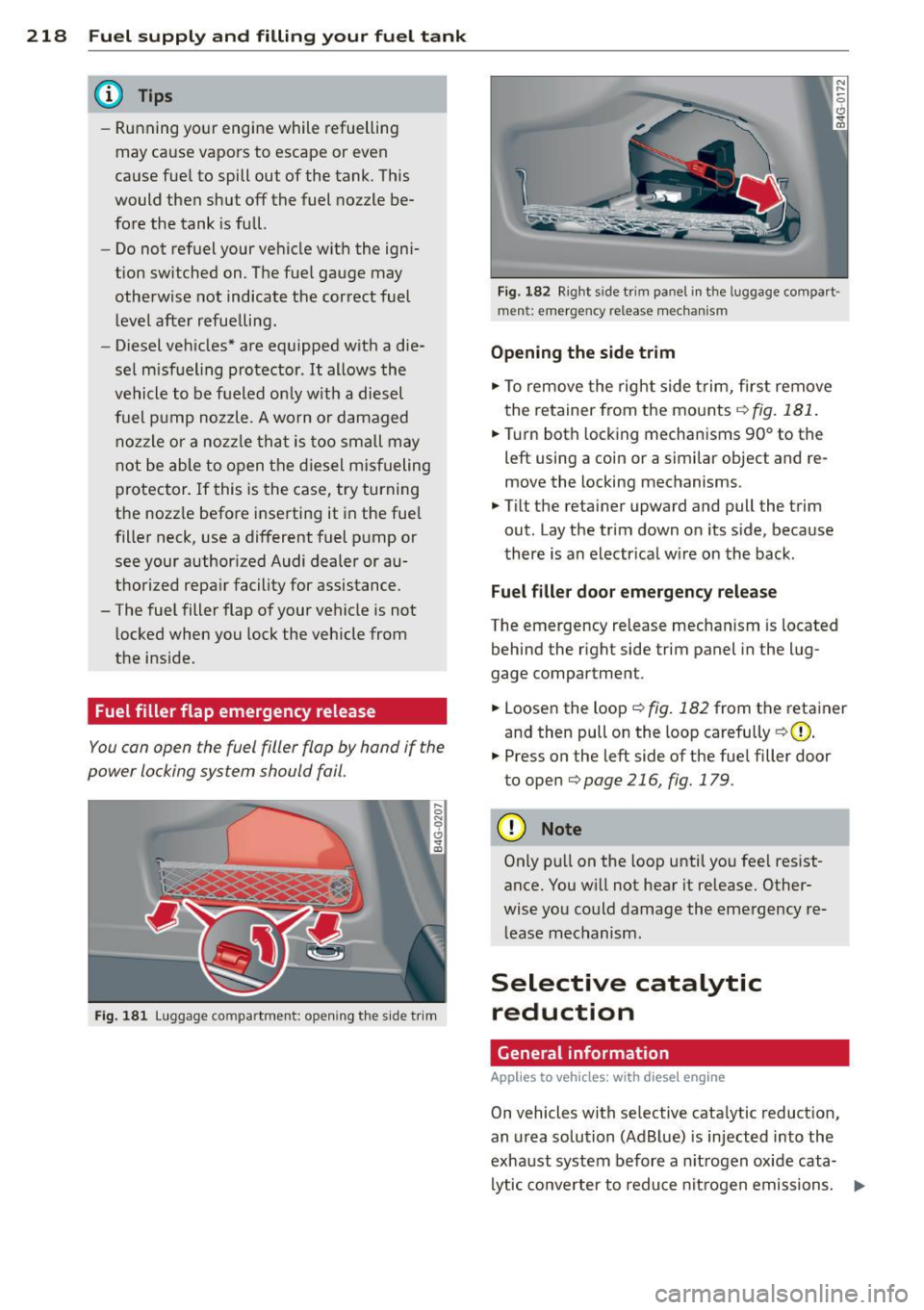
Fuel filler flap emergency release
You can open the fuel filler flap by hand if the
power locking system should fail.
Fig. 181 Luggage compartment: opening the side t rim
Fig. 182 R ight sid e tr im panel in t he luggage compart ·
men t: emergency release mechanism
Opening the side trim
.. To remove the right side trim, first remove
the retainer from the mounts ¢
fig. 181.
.. Turn both locking mechanisms 90° to the
left using a coin or a similar object and re
move the locking mechanisms.
.. Tilt the retainer upward and pull the trim
out. Lay the trim down on its side, because
there is an electr ical wire on the back.
Fuel filler door emergency release
The emergency release mechanism is located
behind the right side trim panel in the lug
gage compartment .
.. Loosen the loop¢
fig. 182 from the retainer
and then pull on the loop carefully
¢ (D .
.. Press on the left side of the fuel filler door
to open
¢ page 216, fig. 179 .
(D Note
Only pull on the loop until you feel resist
ance. You w ill not hear it release. Other
wise you could damage the emergency re
lease mechanism.
Selective catalytic
reduction
General information
Applies to vehicles : wit h diese l eng ine
On vehicles with selective catalytic reduction,
an urea solution (AdBlue) is injected into the
exhaust system before a nitrogen oxide cata
lytic converter to reduce nitrogen emissions. ..,.
Page 221 of 314
M N
0 I.J "". rl I.O
"' rl
"' rl
The AdBlue is stored in a separate tank in the
vehicle. The Ad Blue usage accounts for ap prox imately 0.5% to 1.2% of the diese l fuel
that is used.
You must refill the Ad Bl ue or have it refilled
by your authorized A udi dealer or qualified
workshop as soon as the AdBlue refill mes
sage appears in the instrument cluster
¢page 220.
A WARNING
Failure to heed Ad Blue ref ill information in
the instrument cluste r can prevent the ve
hicle from being started and drive n. If the
vehicle cannot be driven and an eme rgency
a rises, perso na l inju ry can occur.
- Always have t he Ad B lue tank refilled well
before the t an k ru n s dry.
(D Tips
- The instrument cluster display indicates
the distance remaining that can be dr iv
en
¢ page 219. If the Ad Blue tan k is
com plete ly empty, the eng ine will not
star t aga in a fter the ign ition i s swit ched
off.
- Ad Blue is required by l aw to ope rate this
vehicle .
Indicator in the instrument cluster
display
Applies to vehicles: with d iesel e ngine
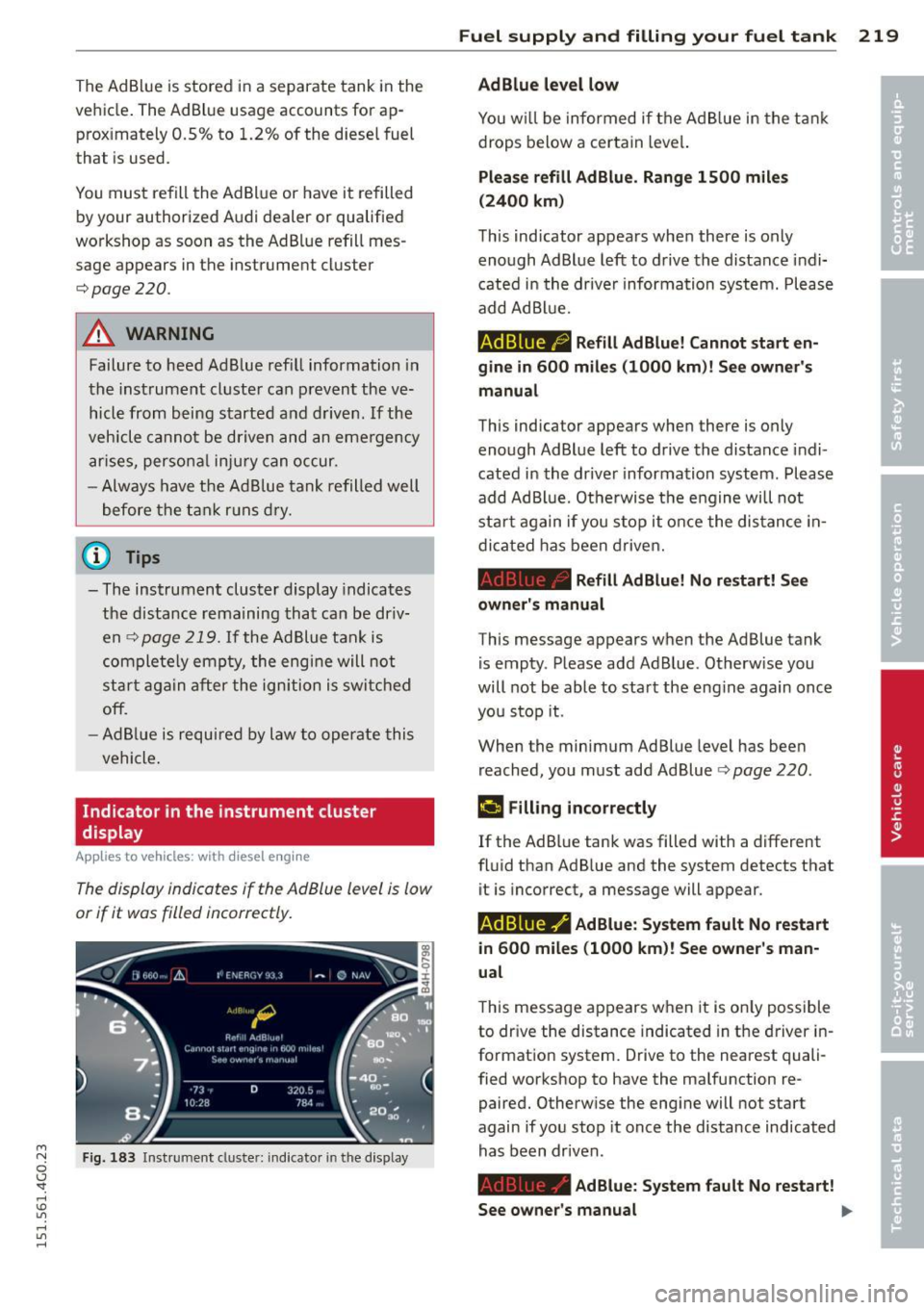
The display indicates if the Ad Blue level is low
or if it was filled incorrectly.
F ig . 18 3 Ins trume nt cluste r: in dicato r in th e d isplay
Fu el suppl y and filli ng your fuel t ank 219
AdBlue level low
Yo u w ill be informed if t he A d Bl ue in the t ank
drops below a certain leve l.
Plea se refill Ad Blue. Range 1500 mile s
(2400 km)
This ind icator appears when there is only
enough Ad Blue left to d rive the distance i ndi
cate d in the drive r informa tion syst em. Please
add AdBl ue.
AdBlue ,0 Refill AdBlue! Cannot start en
gin e in
600 miles (1000 km )! See owner's
manual
This indicator appears whe n there is only
enough Ad Bl ue left to drive the distance indi
cated in the drive r information system. Please
add AdBl ue. Othe rwise the e ngin e w ill not
s tart again if you s top it o nce the di stan ce in
di cated has been driven.
Refill AdBlue! No re start! See
owner's manual
This message appears when the Ad Blue tank
i s empty . Please add Ad B lue. Otherw ise you
will not be able to sta rt the eng ine again once
you stop it.
When the minimum Ad Blue leve l has bee n
reached, you must add Ad Blue¢
page 220 .
&I Filling incorrectly
If the Ad B lue tank was filled with a d ifferent
fluid than Ad B lue and the system detects that
it is incorrect, a message will appear .
AdBlue ,/ AdBlue: System fault No restart
in
600 mile s (1000 km)! See owner 's man
ual
T his message appears when it is on ly possible
to
dr ive the distance indicated in the driver in
format ion system. D rive to the nearest quali
fied workshop to have the ma lfunction re
paired. Otherw ise the eng ine will not start
again if you stop it once the distance indicated
has been dr iven.
Ad Blue: System fault No restart!
See owne r's manual
lilJ,