engine AUDI A7 2012 User Guide
[x] Cancel search | Manufacturer: AUDI, Model Year: 2012, Model line: A7, Model: AUDI A7 2012Pages: 294, PDF Size: 73.33 MB
Page 21 of 294
![AUDI A7 2012 User Guide Instrument s and warnin g/indic ator ligh ts 19
malfunction in the EDL system¢ page 18 4.
See your authorize d Audi dealer as soon as
possible.
A WARNING
- If
the m (USA mode ls)l li] AUDI A7 2012 User Guide Instrument s and warnin g/indic ator ligh ts 19
malfunction in the EDL system¢ page 18 4.
See your authorize d Audi dealer as soon as
possible.
A WARNING
- If
the m (USA mode ls)l li]](/img/6/57604/w960_57604-20.png)
Instrument s and warnin g/indic ator ligh ts 19
malfunction in the EDL system¢ page 18 4.
See your authorize d Audi dealer as soon as
possible.
A WARNING
- If
the m (USA mode ls)l li] (Canada
mode ls) warn ing light does n ot go out,
or if it comes on while driving, the ABS
system is not working properly . The vehi
cle can then be stopped only with the
standard bra kes (without ABS). You will
not have the protection ABS provides.
Contact you r Audi dealer as soon as pos
sible.
- USA models: If the - warning l ight,
the
Ii] warning light and the m warn
ing light come on together, the rea r
wheels co uld lock up first unde r hard
braking. Rear wheel lock-up can cause
loss of vehicle control and an accident .
Have your vehicle repaired immediately
by your autho rized Aud i dea ler or a quali
fied workshop . Drive slowly and avoid
sudden, hard bra ke applications.
- Canada models: If the b rake warn ing
light ., the
DJ warning light and the
ABS wa rning light
rl] come on together ,
the rear w heels could lo ck up fi rst under
h ard bra king . Rear wheel lock-up can
cause loss of vehicle control and an acci
dent. Have yo ur vehicle repaired immed i
ately by your authorized A udi dealer or a
qualified workshop. Dr ive slowly and
avo id sudden, hard brake applicat ions .
(0) Worn brake pads
£1 Bra ke pad s!
If the warn ing light illum inates, immediately
contact your authori zed A udi dealer or quali
fied workshop to have all brake pads inspect
ed. O n USA models the warning light
£1
comes on together with t he war ning light
- · Both sets of brake pads on an axle
mus t always be replaced a t the same time.
1) - : USA m odels on ly
A WARNING
Driving w ith bad brakes can cause a colli
sion and ser ious personal in ju ry .
- If the warn ing light
£1 and the warning
light
11111> with the message Brake
pads!
comes on in the instrument cluster
disp lay, imm ediately contact your au
thori zed A udi dealer or qualified work
shop to have all b rake pads checked or
replace d if necess ary.
EPC Electronic power control
This warning/indicator light monitors the
electronic power control.
The ~ warning/ind icator light (E lectronic
Power Cont rol) illuminates when you switch
the ignit io n on as a fu nction chec k.
(D Tips
If this war ning/ indicator l ight illum inates
while yo u are d riving, then there is a mal
funct io n in the engine electronics. Have
the malf unct ion corrected as soon as pos
si bl e by your au thori zed A udi dealer or
q ualified repa ir facility .
Ci Malfunction Indicator Lamp (MIL)
The Malfunction Indicator Lamp ( MIL) is pa rt
of the On -Board Diagnostic (OBD II) system.
The symbol
fllllijj lights up when the ign ition is
switched on and will tur n off after the engine
has started and has settled at a consta nt idle
speed . This indicates that the MIL is work ing
properly.
The warning lig ht illuminates w hen there is a
malfu nction in the e ng ine electron ic system .
Contact your aut horized Audi dealer and have
the malfunction cor rected.
An improperly closed fuel filler cap may a lso
cause the MI L light to illuminate ¢
page 213.
For more information ¢page 27.
Page 22 of 294
20 Instruments and warning/indicator lights
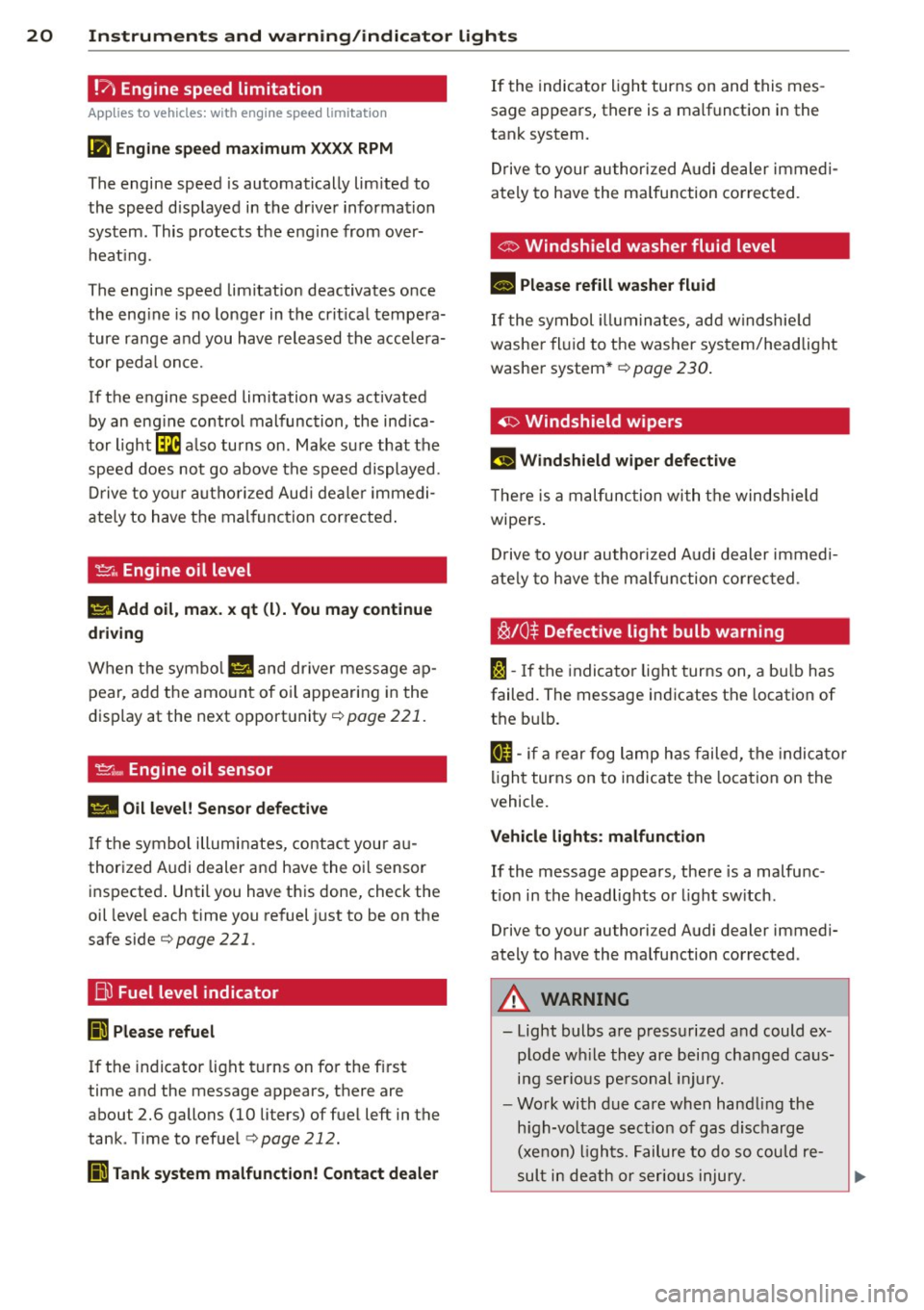
!?' Engine speed limitation
Ap plies to vehicles: wit h eng ine spee d limi tation
(ii Engine speed maximum XXXX RPM
The engine speed is automatically limited to
the speed displayed in the driver information
system. This protects the engine from over
heating.
The engine speed limitation deactivates once
the engine is no longer in the critical tempera
ture range and you have released the accelera
tor pedal once.
If the engine speed limitation was activated by an engine control malfunction, the indica
tor light~ also turns on. Make sure that the
speed does not go above the speed displayed .
Drive to your authorized Audi dealer immedi
ately to have the malfunction corrected.
~ . Engine oil level
II! Add oil, max. x qt (l) . You may continue
driving
When the symbol II and driver message ap
pear, add the amount of oil appearing in the
display at the next opportunity
c:> page 221.
~ .... Engine oil sensor
• Oil level! Sensor defective
If the symbol illuminates, contact your au
thorized Audi dealer and have the oil sensor inspected. Until you have this done, check the
oil level each time you refuel just to be on the
safe side<=>
page 221.
Bil Fuel level indicator
Ji Please refuel
If the indicator light turns on for the first
time and the message appears, there are
about 2.6 gallons (10 liters) of fuel left in the
tank . Time to refuel
<=> page 212.
Ji Tank system malfunction! Contact dealer
If the indicator light turns on and this mes
sage appears, there is a malfunction in the
tank system.
Drive to your authorized Audi dealer immedi
ately to have the malfunction corrected.
o Windshield washer fluid level
B Please refill washer fluid
If the symbol illuminates, add windshield
washer fluid to the washer system/headlight
washer system*
c:> page 230.
~ Windshield wipers
,,., Windshield wiper defective
There is a malfunction with the windshield
wipers.
Drive to your authorized Audi dealer immedi
ately to have the malfunction corrected .
~/0$ Defective light bulb warning
fa-If the indicator light turns on, a bulb has
failed. The message indicates the location of
the bulb.
[I-if a rear fog lamp has failed, the indicator
light turns on to indicate the location on the
vehicle .
Vehicle lights: malfunction
If the message appears, there is a malfunc
tion in the headlights or light switch .
Drive to your authorized Audi dealer immedi
ately to have the malfunction corrected .
A WARNING
-
-Light bulbs are pressurized and could ex-
plode while they are being changed caus
ing serious personal injury.
- Work with due care when handling the
high-voltage section of gas discharge
(xenon) lights. Failure to do so could re
sult in death or serious injury.
Page 24 of 294
22 Instruments and warning/indicator lights
Driver information
display
Overview
Fig. 4 Driver informat ion system in the instrument
cluste r
Fig. S Display: example of the informat ion line
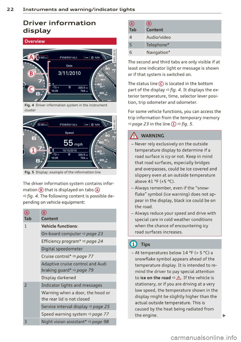
The driver information system contains infor
mation @ that is displayed on tabs @
c:;, fig. 4. The following content is possible de
pending on vehicle equipment:
@
Tab
1
2
3
®
Content
Vehicle functions :
On-board computer c::>page 23
Efficiency program* c> page 24
Digital speedometer
Cruise control*
c:;, page 77
Adaptive cruise control and Audi braking guard*
c::> page 79
Display darkened
Indicator lights and messages
Warning when a door, the hood or the rear lid is not closed
Service interval display
c:;, page 25
Speed warning system c:> page 77
Night vision assistant*
c:> page 98
-@ ®
Tab Content
4 Audio/video
5 Telephone*
6 Navigation*
The second and third tabs are only visible ifat
least one indicator light or message is shown
or if that system is switched on.
The status line © is located in the bottom
part of the display ¢
fig. 4. It displays the ex
terior temperature, time, selector lever posi
tion, trip odometer and odometer.
For some vehicle functions, you can access the
trip information from the temporary memory
c:> page 23 in the line (D c::> fig. 5.
A WARNING
--
-Never rely exclusively on the outside
temperature display to determine if a
road surface is icy or not. Keep in mind
that road surfaces , especially bridges
and overpasses, could be ice covered and
slippe ry even at an outside temperature
above 41 °F (+S °C).
- Always remember, even if the "snow
flake" symbo l (ice warning) does not ap
pear in the d isp lay, black ice cou ld be on
the road.
- Always reduce your speed and drive with
specia l care in cold weather conditions
when the chance of encountering icy
road surfaces increases.
(D Tips
- At temperatures below 14 °F (+ 5 °C) a
snowf lake symbol appears ahead of the
temperature display. It is intended to re
mind the driver to pay special attention
to
ice on the road c:> .&.. If the vehicle is
stationary, or if you are driving at a very
low speed, the temperature shown in the
display might be slightly h igher than the
actual outside temperature. This is
caused by the heat being radiated from
th e engine.
Page 29 of 294
Instrument s and warning /indicator lights 2 7
Display content
In the MMI, you ca n specify which information
should be displayed :
- Cru ise cont ro l system*
- Nav igat io n info rmation *
- Audi adaptive cruise control*
- N ight vision assistant* (pedestr ian warn ing)
The speed display and some of the red indica
tor lights cannot be hidden in the MMI.
Display brightness
You can adj ust t he display b rightness in the
M MI. The display brightness decreases auto
ma tica lly as the amount o f light dec reases.
The basic leve l o f brightness is adjusted wi th
the instrument illumination ¢
page 44.
(D Note
To prevent s cratc h es on t he g lass co vering
t he Head -up Disp lay , do not place any ob
jects in the projection opening.
@ Tips
- Sun glasses w ith polar izat ion fi lters and
u nfav orable ligh ting condit ions can af
fect the disp lay.
- Vehicles wi th seat memory *: yo ur Head
up D isplay sett ings a re stored automati
ca lly and assigne d to the remote contro l
k ey that you are us ing.
- A specia l windshield is needed for the
Head-up Display functio n.
On-Board Diagnostic
system (OBD)
Malfunction Indicator Lamp (MIL)
The Malfunction Indicator Lamp (MIL) ISi in
the instrument cluster is part of the On-Board
Diagnostic (OBD II) system.
The warning/indicator light illumina tes when
the ignition is switched on and goes o ut after
the engine starts and the idle has stabi lized.
This indicates that the MIL is work ing proper
ly.
If the light does not go out after t he engine
is started, or illuminates while you are driv
i ng, a mal function may e xist in the eng ine sys
tem.
If the light illumi nates, the catalytic con
verter could be damaged .
Contin ue d riving
with reduced power (avoid
i ng s usta ined h igh speeds and/or rapid accel
erations) and have the cond ition corrected .
Contact your a uthorized Audi dea ler.
If the light illuminates, the e lectronic speed
li miter may also be malfunct ion ing. For more
i nformation ¢
page 2 8, Electronic speed
limiter.
An improperl y closed fuel filler cap may also
cause the MIL light to illuminate
<=> page 213.
On-Board Diagnostics
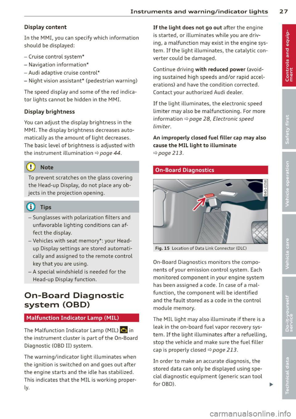
Fig. 15 Location of Data Li nk Co nnector (D LC)
On-Boa rd Diagnost ics monitors the compo
nents of your em issio n cont ro l system . Eac h
monitored component in your engine system
has been assigned a code. In case of a mal
functio n, the component will be identified
and t he fault stored as a code in the control
module memo ry .
The MIL light may also illuminate if there is a leak in the on-board f uel vapor recovery sys
tem. If the lig ht illum inates afte r a refuelling,
stop the vehicle a nd make sure the fuel fille r
cap is properly closed
¢ page 213.
In order to make an accurate diagnosis , the
stored data can o nly be disp layed using spe
c ial diagnostic equipment (generic scan tool
fo r OBD). .,.
Page 30 of 294
28 Instruments and warning/indicator lights
In order to connect the special diagnostic
equipment, push the plug into the Data Link
Connector (DLC). The DLC is located to the
right of the hood release¢
fig. 15.
Your authorized Audi dealer or a qualified
service station can interpret the code and per
form the necessary repair.
Electronic speed limiter
Your vehicle may be factory equipped with tires that are rated for a maximum speed of 130 mph (210 km/h) . This is less than the
maximum speed of your vehicle . To reduce the
risk of sudden tire failure and loss of control if
the vehicle is operated at excessive speeds,
your vehicle also has an electronic speed limit
er. The electronic speed limiter prevents your
vehicle from going faster than the tire speed rating. For more information
c::> page 242.
If the engine control unit receives faulty vehi
cle road speed signals, the Malfunction Indi
cator Lamp (MIL)
II will illuminate. If this
occurs, contact the nearest authori zed Audi
dealer for assistance.
A WARNING
-
Always observe the posted speed limits
and adjust your speed to suit prevailing
road, traffic and weather conditions. Never
drive your vehicle faster than the maxi
mum speed rating of the tires installed.
Page 31 of 294
Opening and closing Keys
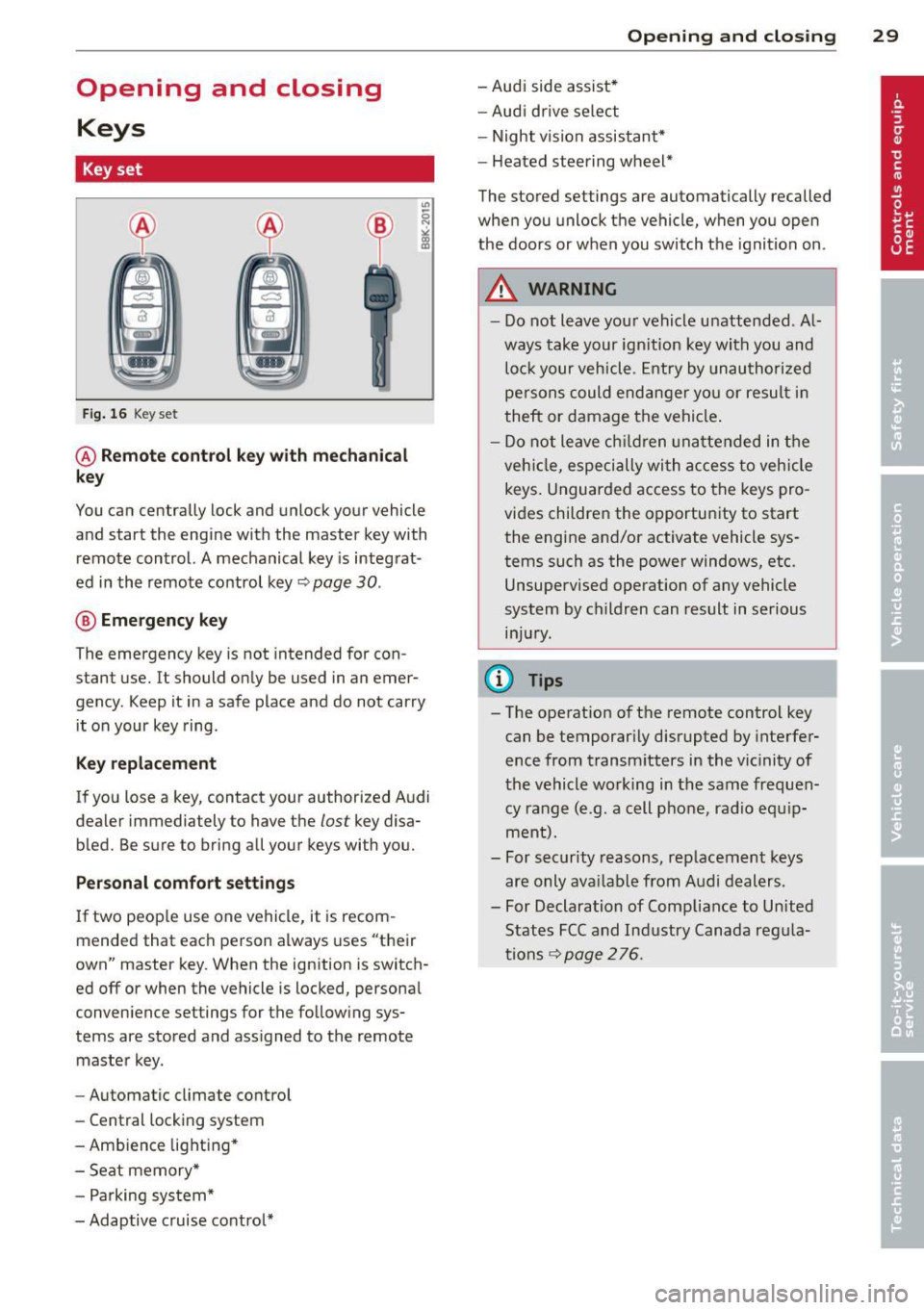
Key set
Fig. 16 Key set
@ Remote control key with mechanical
key
You can centrally lock and unlock your vehicle
and start the engine with the master key with
remote control. A mechanical key is integrat
ed in the remote control key~
page 30.
® Emergency key
The emergency key is not intended for con
stant use.
It should only be used in an emer
gency . Keep it in a safe place and do not carry
it on your key ring .
Key replacement
If you lose a key, contact your authorized Audi
dealer immediately to have the
lost key disa
bled. Be sure to bring all your keys with you.
Personal comfort settings
If two people use one vehicle, it is recom
mended that each person always uses "their
own" master key. When the ignition is switch
ed
off or when the vehicle is locked, personal
convenience settings for the following sys
tems are stored and assigned to the remote
master key.
- Automatic climate control
- Central locking system
- Ambience lighting*
- Seat memory*
- Parking system*
- Adaptive cruise control*
Opening and closing 29
- Audi side assist*
- Audi drive select
- Night vision assistant*
- Heated steering wheel*
The stored settings are automatically recalled
when you unlock the vehicle, when you open
the doors or when you switch the ignition on.
A WARNING
---Do not leave your vehicle unattended . Al
ways take your ignition key with you and
lock your vehicle. Entry by unauthorized
persons could endanger you or result in
theft or damage the vehicle.
- Do not leave children unattended in the
vehicle, especially with access to vehicle
keys. Unguarded access to the keys pro
vides children the opportunity to start the engine and/or activate vehicle sys
tems such as the power windows, etc. Unsupervised operation of any vehicle
system by children can result in serious
injury.
{!) Tips
- The operation of the remote control key can be temporarily disrupted by interfer
ence from transmitters in the vicinity of
the vehicle working in the same frequen
cy range (e .g. a cell phone , radio equip
ment).
- For security reasons, replacement keys
are only available from Audi dealers.
- For Declaration of Compliance to United
States FCC and Industry Canada regula
tions
~ page 276.
Page 32 of 294
30 Opening and clo sing
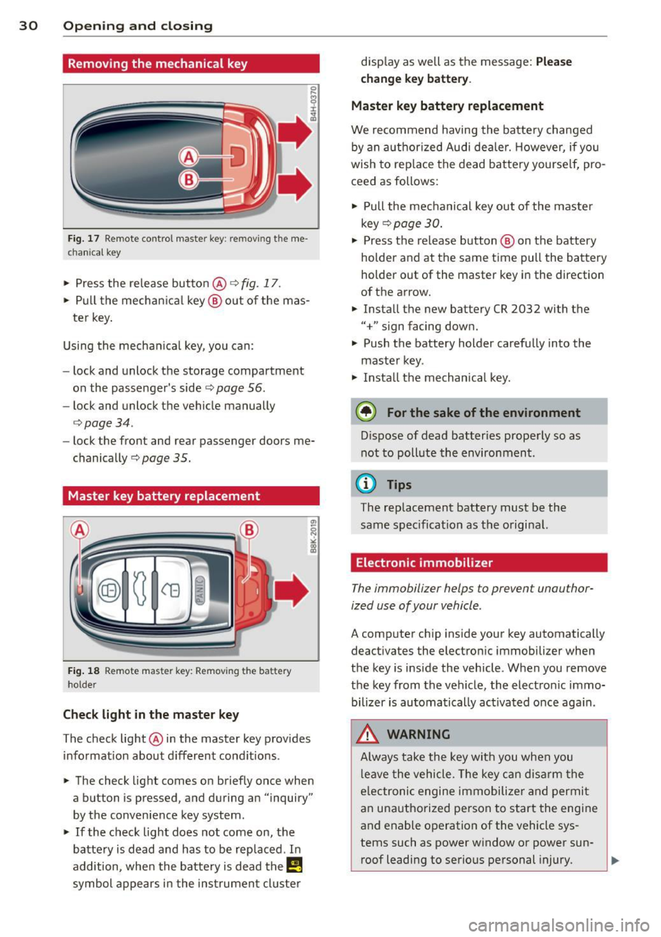
Removing the mechanical key
Fig. 17 Remote control master key: remo vin g the me
ch ani cal key
> Press the release button @ c:> fig. 17 .
.. Pull the mecha nica l key @out of the mas
te r key.
Using the mechan ica l key, you can:
- lock and unlock the storage compartment
on the passenger's side
c:> page 56.
- lock and unlock the vehicle manually
<=>page 34.
-lock the front and rear passenger doors me
chanically
c:> page 35.
Master key battery replacement
Fig . 18 Remote mas ter key: Removing the batter y
ho lder
Ch eck light in the master ke y
The check light @in the master key provides
information about d ifferent cond itions .
.. The check light comes on briefly once when
a button is pressed , and during an "inquiry"
by the convenience key system .
> If the check light does not come on, the
battery is dead and has to be replaced . In
addition, when the bat tery is dead the
I!
symbol appears in the instrument cluster disp
lay as well as the message:
Ple ase
c h ange key batt ery.
Ma ster key batter y replacement
We recommend having the batte ry changed
by an authorized Audi deale r. However, if you
wish to rep lace the dead battery yourse lf, pro
ceed as follows:
> Pull the mechanical key out of the master
key
c:> page 30 .
.. Press the release button @ on the battery
holder and at the same time pull the battery
holder out of the master key in the direction
of the arrow .
.. Install the new battery CR 2032 with the
"+" sign facing down.
> Push the battery holder carefully into the
maste r key .
> Insta ll the mechanical key.
@ For the sake of the env ironment
D ispose of dead batteries properly so as
not to pollute the environment.
(D Tips
The replacement battery must be the
same specification as the original.
Electronic immobilizer
The immobilizer helps to prevent unauthor
ized use of your vehicle .
A computer chip ins ide your key automatically
deactivates the electronic immobilizer when
the key is inside the vehicle . When you remove
the key from the vehicle, the electron ic immo
bilizer is automatically ac tivated once aga in .
.&, WARNING
-
A lways take the key with you when you
l eave the vehicle . T he key can disarm the
e lectronic engine immobilize r and permi t
an unauthorized person to start the engine
and enable operation of the vehicle sys
tems such as power window or power sun- roof leading to serious personal injury.
~
Page 35 of 294
Locking and unlocking the vehicle with
the remote control
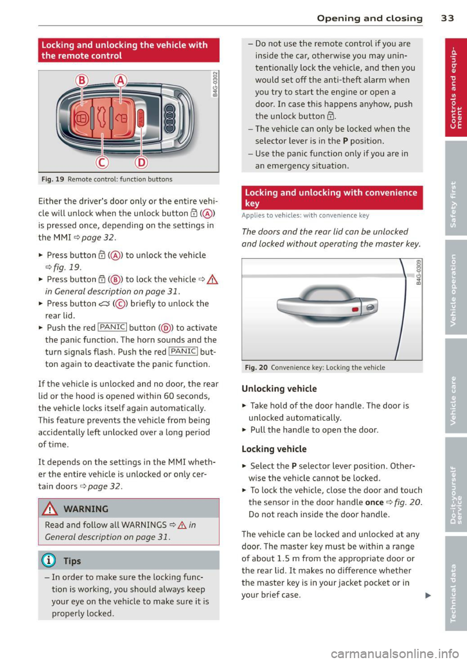
F ig. 19 Remote control: func tion buttons
Either the dr iver's door only or the entire veh i
cle will unlock when the unlock button
en(@)
is pressed once, depend ing on the settings in
the MMI
c>page 32.
.. Press button 0 (@ ) to unlock the vehicle
¢fig. 19 .
.. Press button {f) (@ ) to lock the vehicle q .&.
in General description on page 31 .
.. Press button cs(@) briefly to unlock the
rear lid .
.. Push the red
!PANIC I button( @) to activate
the panic function. The horn sounds and the
turn signal s flash. Push the red
I PANIC ! but
ton again to deactivate the panic function.
If the vehicle is unlocked and no door, the rear
lid or the hood is opened within 60 seconds,
the vehicle locks itself again automatically .
This featu re prevents the vehicle from being
accidentally left unlocked over a long period
of time .
It depends on the settings in the MMI wheth
er the entire vehicle is unlocked or only cer
tain doors
r::> page 32.
A WARNING
Read and follow all WARNINGS ¢.&. in
General description on page
31.
@ Tips
-In order to make sure the locking func
tion is working, you should always keep
your eye on the vehicle to make sure it is
properly locked.
Opening and closing 33
-Do not use the remote cont rol if you are
inside the car, otherwise you may unin
tentionally lock the vehicle, and then you
would set
off the anti-theft alarm when
you try to start the engine or open a
door . In case this happens anyhow, push
the unlock button@ .
- The veh icle can only be locked when the
selector lever is in the
P posit ion.
- Use the panic function only if you are in
an emergency situation .
Locking and unlocking with convenience
key
Applies to vehicles: w ith conven ience key
The doors and the rear lid can be unlocked
and locked without operating the master key .
Fig. 20 Conve nience key : Lock ing th e vehicle
Unlocking vehicle
.. Take hold of the door handle . Th e door is
un locked automat ically.
.. Pull the handle to open the door.
Locking vehicle
.. Select the P selector lever position . Other
w ise the veh icle cannot be locked.
.. To lo ck the veh icle, close the door and touch
the sensor in the door handle
once c> fig. 20.
Do not reach inside the door handle .
T he vehicle can be locked and unlocked at any
door. The master key must be within a range
of about 1.5 m from the appropriate door or
the rear lid. It makes no difference whether
the master key is in your jacket pocket or in
your brief case.
Page 40 of 294
38 Opening and closing
Power windows
Controls
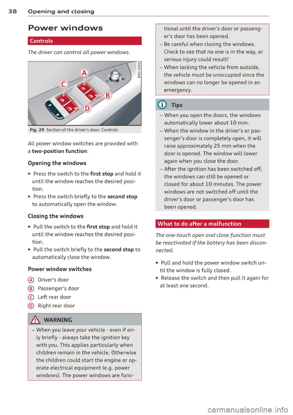
The driver can con trol all power windows.
"' N 0 0 6
Fig . 29 Sect io n of the drive r's d oor : Contro ls
"' m
All power window sw itches are provided with
a two -pos ition function:
Opening the windows
.. Press the switch to the first stop and ho ld it
until the window reaches the desired posi
tion .
.. Press the switch briefly to the
second stop
to automatically open the window .
Closing the windows
.. Pull the switch to the first stop and hold it
until the window reaches the desired pos i
t ion.
.. Pull the switch briefly to the
second stop to
automa tically close the window .
Power window switches
@ Driver's door
@ Passenger's door
© Left r ear door
@ Right rear door
_& WARNING
- When you leave your veh icle -even if on
ly brief ly -always take the ignition key
with you. This applies particu larly when
children remain in the veh icle. Otherwise
the chi ldren could start the engine or op
erate electrical equipment (e.g . power
windows). The power windows are func- tional
until the driver's door or passeng
er's door has been opened.
- Be careful when closing the windows.
Check to see that no one is in the way, or
serious injury could result!
- When locking the vehicle from outside,
the vehicle must be unoccupied since the
windows can no longer be opened in an
emergency.
@ Tips
- When you open the doors, the windows
automatically lower about 10 mm .
- When the window in the driver's or pas
senger's door is complete ly open, it wi ll
raise approximately 25 mm when the
door is opened . The window will lower
again when you close the door .
- After the ignition has been switched off,
the windows can still be opened or closed for about 10 minutes . The power
w indows are not switched off until the
dr iver's door or passenger's door has
been opened.
What to do after a malfunction
The one-touch open and close function must
be reactivated if the battery has been discon
nected .
.. Pull and hold the power window switch un
til the w indow is fully closed .
.. Release the switch and then pull it again for
at least one second.
Page 57 of 294

12-volt sockets
Fig. 53 Section of the trim panel of the luggage com
partment: 12-volt socket
Fig . 54 Rear center console: 12-volt socket
~ To reach the 12-volt socket in the luggage
compartment, press the net down or re
move the bracket from the mounts
Qfig . 53.
There is an additional 12-volt socket in the
front and rear center console¢
fig. 54.
0 5 0
/li
The 12 volt sockets may be used for 12-volt
appliances with max imum cons umption of up
to 120 watts.
Before you purchase any accessories, always
r ead and fol low the information in
¢ page 2 75, Additional accessories and parts
replacement .
A WARNING
The sockets and the e lectrica l accessories
connected to them operate on ly when the
ignition is switched on. Incorrect usage
can lead to serious injuries or burns. To re
duce the risk of injuries, never leave chil
dren unattended in the vehicle with the ve
hicle key.
S ea ts a nd s to rage 55
(D Note
To avoid damaging the socket, only use
plugs that fit properly.
- Never connect equipment that generates
electrical current, such as a solar pane l
or battery charger, to the 12 volt socket.
This could damage the vehicle's electri cal system.
- The 12 volt socket shou ld only be used
for a short period of ti me as a power
source for electrical equ ipment. Please
use the electr ical sockets in the vehicle
when con necting equ ipment for longer
periods.
- To avoid damaging the socket, only use
plugs that fit properly.
(D Tips
When the engine is off and accessories are
still plugged in and are on, the vehicle ba t
tery can still be d rained.
Storage
(upholder
Fi g. 55 Ce nter console: cupholder
Fig. 56 Rear center armrest: cupholde r extended