tire pressure AUDI A7 2021 Owner´s Manual
[x] Cancel search | Manufacturer: AUDI, Model Year: 2021, Model line: A7, Model: AUDI A7 2021Pages: 350, PDF Size: 126.66 MB
Page 6 of 350
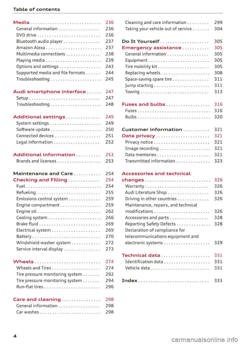
Table of contents
Co | fan a 236
General information................. 236
DVD: drive « swe s 2 awe 2 ewes 2 ewe see 236
Bluetooth audio player............... 237
Amazon Alexa.... 2.0.0. cece eee eee 237
Multimedia connections.............. 238
Playing medias. « & ssc 2c ewae « owe oo ee 239
Options
and settings................. 243
Supported media and file formats...... 244
Troubleshooting ewies 2 < sce se enw so xy 245
Audi smartphone interface...... 247
S@tUD « ses + y gam peas + yoms os Bene 247
Troubleshooting.............-..00005 248
Additional settings.............. 249
Systemisettingsc « + cssuene so mvswee a soseeue vs 249
Software update........... 0.0 e eee 250
Connected devices..............2---5 251
Legal.information ss « sess s+ ama sx ween « 252
Additional information.......... 253
Brands and licenses...............-4- 253
Maintenance and Care........... 254
Checking and Filling............. 254
Fuel... cee eee 254
Refueling ......... 0... ce eee ee eee eee 255
Emissions control system............. 259
Engine compartment.............+06% 259
Engineoil........ 00... eee eee eee 262
COOLINGSYSEEM « « sees & = nets 5 = eetew so ore 266
Brake:fluid «2 csoswe s 2 wscceve ov eevee oo erm 269
Electrical system. ...........002-0 00 269
Battery: » = sees = » mean 5 4 meee ye ee Gt BE 270
Windshield washer system...........- 272
Service interval display............... 273
WWATEBUSE. core 5 6 sae oo sms oo ee oo oe 274
Wheels and Tires...........--0000 00s 274
Tire pressure monitoring system....... 292
Tire pressure monitoring system....... 294
Run-flat tires... 2.2... cee eee eee eee 296
Care and cleaning................ 298
General information..............4.. 298
Car washes ........... 0000 e eee ee eee 298
Cleaning and care information......... 299
Taking your vehicle out of service....... 304
Doilt Yoursell eis ics tiie as nscwa so ease 305
Emergency assistance........... 305
General information................. 305
EQUIPIMIENE sso 6s cass a 2 sam o & aueeM wow 305
Tire mobility kit.............0...000. 305
Replacing wheels................-.4. 308
Space-saving spare tire............... 311
JUN PESTAREIAG « x sensves » a seemme @ » emcee oo econ 311
TOWING... 2 eee eee eee ee 313
Fuses and bulbs.................. 316
Fuses... 0... eee eee eee 316
Bul BSc = = geupe 2 » eeu ¢ e meuee xe Ee a eS 320
Customer information........... 321
Data privacy...................... 324:
Privacy NOtiCe « iesis 2s moms + eee ¥ wee 321
Image recording................-.00. 321
Data memories............0.ceeeeeee 321
Transmitted information.............. 323
Accessories and technical
CHANGES: « « owes 5 ¢ sews + & eeu bc eS oe 326
Wa Plat yiis < s eseceits © + seavene i + snereie © w omneete 326
Audi Literature Shop..............0-- 326
Driving in other countries............. 326
Maintenance, repairs, and technical
modifications..................00008 326
Accessories and parts..............-. 328
Reporting Safety Defects.............. 328
Declaration of compliance for
telecommunications equipment and
electronicisystemsi. se sve sx esis 2 x ee 329
Technical data.................... 331
Identification data................00. 331
Vehicle data........... 0... cee eee eee 331
TMAOX:: « s sence 3 2 neem © 2 eens © x eee 2 Be 333
Page 11 of 350

4K8012721BF
Quick access
Anti-lock braking system (ABS) Maneuver assist
=>page 117 => page 196
Steering Tire pressure
=>page 114 => page 292, > page 294
Steering lock Tire pressure
>page 114 = page 292, > page 294
All wheel drive Loose wheel warning
=>page 115 => page 289
Suspension control Bulb failure indicator
=> page 113 = page 56
Air suspension Adaptive light
=> page 113 => page 56
Rear spoiler Light/rain sensor
>page 118 = page 56, > page 61
Engine speed limitation Door lock
>page 15 => page 38
Tank system Battery in vehicle key
=>page 255 = page 42
Tank system/high-voltage system Night vision assist
>page 255 => page 149
Electrical system Intersection assist
=> page 269 = page 174
Engine oil level (MIN) Side assist
=> page 263 => page 172;
Engine oil level (MAX) Exit warning
> page 263 = page 172
Rear cross-traffic assist
Engine oil sensor
= page 183
=> page 263
Adaptive cruise assist
Malfunction Indicator Lamp (MIL)
=> page 163
=> page 259,
Steering intervention request
Engine warm-up request
=> page 158, > page 165
=> page 263
Washer fluid level
=> page 273
Windshield wipers
> page 61
High-voltage battery range
=>page 125
Lane departure warning
=> page 166
Distance warning
=> page 164
Audi pre sense
=> page 170
Emergency assist
Parking systems
=>page 174
=>page 178
Park assist plus ae: call function
page 190 page 214 >
9
Page 18 of 350
Instrument cluster
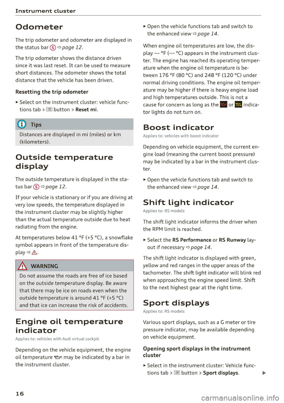
Odometer
The trip odometer and odometer are displayed in
the status bar ©) > page 12.
The trip odometer shows the distance driven
since it was last reset. It can be used to measure
short distances. The odometer shows the total
distance that the vehicle has been driven.
Resetting the trip odometer
> Select on the instrument cluster: vehicle func-
tions tab > =] button > Reset mi.
@ Tips
Distances are displayed in mi (miles) or km
(kilometers).
Outside temperature
display
The outside temperature is displayed in the sta-
tus bar ©) 9 page 12.
If your vehicle is stationary or if you are driving at
very low speeds, the temperature displayed in
the instrument cluster may be slightly higher
than the actual temperature outside due to heat
radiating from the engine.
At temperatures below 41 °F (+5 °C), a snowflake
symbol appears in front of the temperature dis-
play > A.
Z\ WARNING
Do not assume the roads are free of ice based
on the outside temperature display. Be aware
that there may be ice on roads even when the
outside temperature is around 41 °F (+5 °C)
and that ice can increase the risk of accidents.
Engine oil temperature
indicator
Applies to: vehicles with Audi virtual cockpit
Depending on the vehicle equipment, the engine
oil temperature %7 may be indicated by a bar in
the instrument cluster.
16
> Open the vehicle functions tab and switch to
the enhanced view > page 14.
When engine oil temperatures are low, the dis-
play --- °F (--- °C) appears in the instrument clus-
ter. The engine has reached its operating temper-
ature when the engine oil temperature is be-
tween 176 °F (80 °C) and 248 °F (120 °C) under
normal driving conditions. The engine oil temper-
ature may be higher if there is heavy engine load
and high temperatures outside. This is not a
cause for concern as long as the E or = indica-
tor lights do not turn on.
Boost indicator
Applies to: vehicles with boost indicator
Depending on vehicle equipment, the current en-
gine load (meaning the current boost pressure)
may be indicated by a bar in the instrument clus-
ter.
> Open the vehicle functions tab and switch to
the enhanced view > page 14.
Shift light indicator
Applies to: RS models
The shift light indicator informs the driver when
the RPM limit is reached.
> Select the RS Performance or RS Runway lay-
out if necessary > page 14.
The shift light indicator is displayed with green,
yellow and red ranges in the upper areas of the
tachometer. The shift light indicator will blink red
when approaching the engine speed limit. Shift
to the next highest gear at the right time.
Sport displays
Applies to: RS models
Various sport displays, such as a G meter or tire
pressure indicator, may be available depending
on vehicle equipment.
Opening sport displays in the instrument
cluster
> Select in the instrument cluster: Vehicle func-
tions tab > EE] button > Sport displays.
Page 19 of 350
4K8012721BF
Instrument cluster
> Turn the left thumbwheel on the multifunction
steering wheel until the desired sport display
appears in the instrument cluster.
Opening sport displays in the MMI
> Applies to MMI: Select on the home screen: VE-
HICLE > RS monitor.
> Browse to the desired display if necessary.
G meter
The G meter displays the longitudinal and lateral
acceleration. The current values are displayed in
the instrument cluster while driving. The maxi-
mum values that are reached are stored and dis-
played when the vehicle is stationary. Only the
maximum values that are reached are displayed
in the MMI.
> To reset the stored values, press and hold the
left thumbwheel on the multifunction steering
wheel for one second.
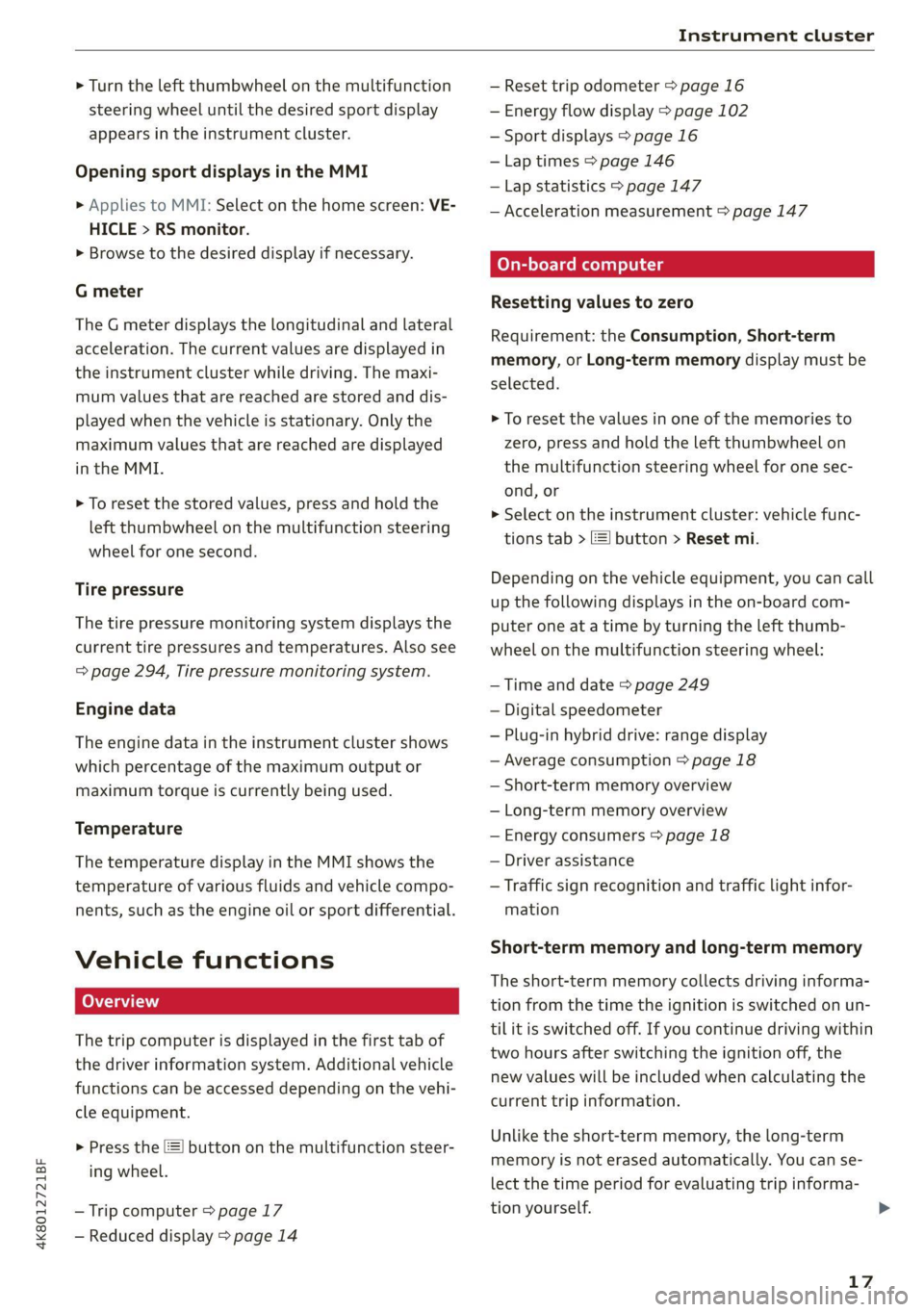
Tire pressure
The tire pressure monitoring system displays the
current tire pressures and temperatures. Also see
= page 294, Tire pressure monitoring system.
Engine data
The engine data in the instrument cluster shows
which percentage of the maximum output or
maximum torque is currently being used.
Temperature
The temperature display in the MMI shows the
temperature of various fluids and vehicle compo-
nents, such as the engine oil or sport differential.
Vehicle functions
The trip computer is displayed in the first tab of
the driver information system. Additional vehicle
functions can be accessed depending on the vehi-
cle equipment.
> Press the =] button on the multifunction steer-
ing wheel.
— Trip computer > page 17
— Reduced display > page 14
— Reset trip odometer > page 16
— Energy flow display > page 102
— Sport displays > page 16
— Lap times > page 146
— Lap statistics > page 147
— Acceleration measurement > page 147
On-board computer
Resetting values to zero
Requirement: the Consumption, Short-term
memory, or Long-term memory display must be
selected.
> To reset the values in one of the memories to
zero, press and hold the left thumbwheel on
the multifunction steering wheel for one sec-
ond, or
> Select on the instrument cluster: vehicle func-
tions tab > E] button > Reset mi.
Depending on the vehicle equipment, you can call
up the following displays in the on-board com-
puter one at a time by turning the left thumb-
wheel on the multifunction steering wheel:
— Time and date > page 249
— Digital speedometer
— Plug-in hybrid drive: range display
— Average consumption > page 18
— Short-term memory overview
— Long-term memory overview
— Energy consumers > page 18
— Driver assistance
— Traffic sign recognition and traffic light infor-
mation
Short-term memory and long-term memory
The short-term memory collects driving informa-
tion from the time the ignition is switched on un-
tilit is switched off. If you continue driving within
two hours after switching the ignition off, the
new values will be included when calculating the
current trip information.
Unlike the short-term memory, the long-term
memory is not erased automatically. You can se-
lect the time period for evaluating trip informa-
tion yourself.
17
>
Page 71 of 350
4K8012721BF
Sitting correctly and safely
Correct safety belt positioning
B4H-0751
RAZ-0696
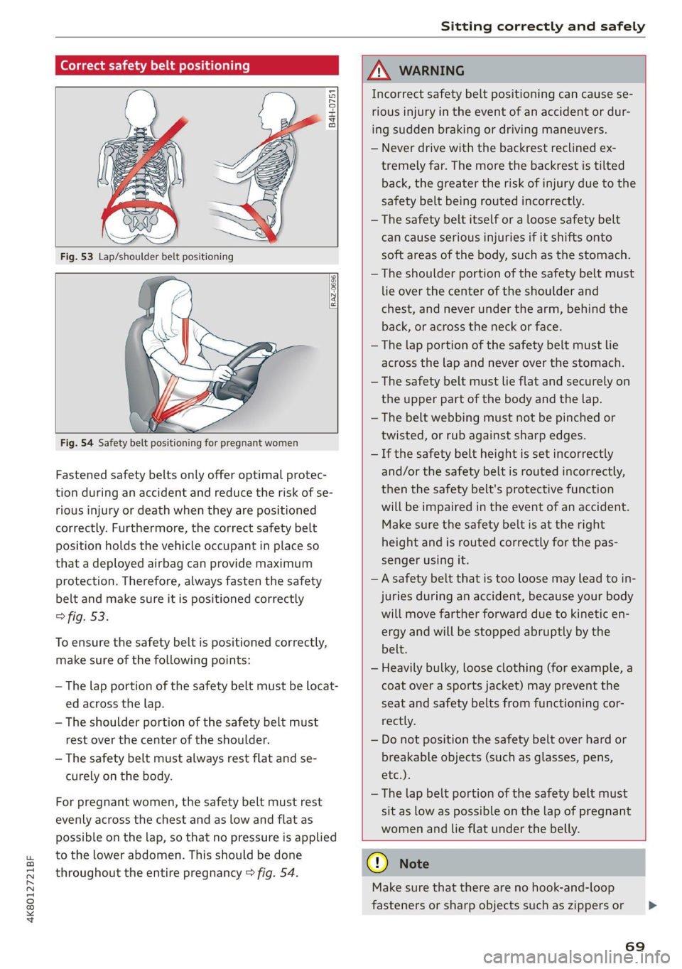
Fastened safety belts only offer optimal protec-
tion during an accident and reduce the risk of se-
rious injury or death when they are positioned
correctly. Furthermore, the correct safety belt
position holds the vehicle occupant in place so
that a deployed airbag can provide maximum
protection. Therefore, always fasten the safety
belt and make sure it is positioned correctly
> fig. 53.
To ensure the safety belt is positioned correctly,
make sure of the following points:
— The lap portion of the safety belt must be locat-
ed across the lap.
—The shoulder portion of the safety belt must
rest over the center of the shoulder.
— The safety belt must always rest flat and se-
curely on the body.
For pregnant women, the safety belt must rest
evenly across the chest and as low and flat as
possible on the lap, so that no pressure is applied
to the lower abdomen. This should be done
throughout the entire pregnancy > fig. 54.
ZA\ WARNING
Incorrect safety belt positioning can cause se-
rious injury in the event of an accident or dur-
ing sudden braking or driving maneuvers.
— Never drive with the backrest reclined ex-
tremely far. The more the backrest is tilted
back, the greater the risk of injury due to the
safety belt being routed incorrectly.
— The safety belt itself or a loose safety belt
can cause serious injuries if it shifts onto
soft areas of the body, such as the stomach.
— The shoulder portion of the safety belt must
lie over the center of the shoulder and
chest, and never under the arm, behind the
back, or across the neck or face.
— The lap portion of the safety belt must lie
across the lap and never over the stomach.
—The safety belt must lie flat and securely on
the upper part of the body and the lap.
— The belt webbing must not be pinched or
twisted, or rub against sharp edges.
— If the safety belt height is set incorrectly
and/or the safety belt is routed incorrectly,
then the safety belt's protective function
will be impaired in the event of an accident.
Make sure the safety belt is at the right
height and is routed correctly for the pas-
senger using it.
— A safety belt that is too loose may lead to in-
juries during an accident, because your body
will move farther forward due to kinetic en-
ergy and will be stopped abruptly by the
belt.
— Heavily bulky, loose clothing (for example, a
coat over a sports jacket) may prevent the
seat and safety belts from functioning cor-
rectly.
— Do not position the safety belt over hard or
breakable objects (such as glasses, pens,
etc.).
—The lap belt portion of the safety belt must
sit as low as possible on the lap of pregnant
women and lie flat under the belly.
@) Note
Make sure that there are no hook-and-loop
fasteners or sharp objects such as zippers or
69
>
Page 86 of 350
Storage and convenience
— The cargo net* is only strong enough to se-
cure light objects. Heavy objects are not ade-
quately secured. Attempting to secure heavy
objects increases the risk of injury.
— Never exceed the permitted axle and load
and vehicle weight > page 332.
— Never secure a child safety seat to the tie-
downs.
— Never leave your vehicle unattended, espe-
cially if the luggage compartment lid is
open. Children could enter the luggage com-
partment and close the luggage compart-
ment lid from the inside. This creates the
risk of fatal injury, since the children would
be locked in and may not be able to escape
by themselves.
— Do not allow children to play in or on the ve-
hicle. Close and lock the luggage compart-
ment lid as well as all other doors when you
leave
the vehicle.
— Never transport passengers in the luggage
compartment. Every passenger must be cor-
rectly secured with the safety belts in the
vehicle > page 68.
— Be careful when releasing the backrest and
folding
it forward. To reduce the risk of be-
ing pinched, pay attention and check when
folding backrests forward.
— The backrest must be securely latched so
objects cannot slide forward out of the lug-
gage compartment during sudden braking.
— The backrest must be latched securely to en-
sure that the safety belt is protecting the
center seating position.
— Always pull forward on the backrest to make
sure it is check if it is correctly locked in
place.
bench seat to protect the backrest from
damage.
— If you move the front seat back when the
rear seat backrest is folded forward, you
could damage the head restraints on the
rear seat.
— Make sure that the heating grid strips for
the rear window defogger are not damaged
by abrasive objects.
— Plug-in hybrid drive: Never exceed the maxi-
mum cargo weight for the cargo floor that is
specified on the sticker. Otherwise, the
high-voltage battery that is located under-
neath the cargo floor could be damaged.
The sticker is located on the inside of the ve-
hicle body at the left, and is visible when the
luggage compartment lid is open.
@ Tips
— The tire pressure must be adapted to the
load > page 284.
— You can purchase straps at specialty stores.
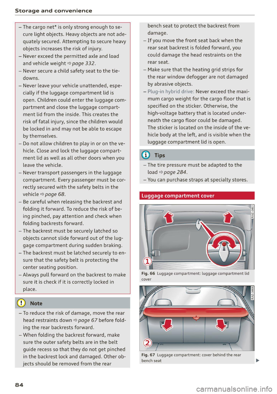
Luggage compartment cover
—_a
@) Note
—To reduce the risk of damage, move the rear
head restraints down > page 67 before fold-
ing the rear backrests forward.
— When folding the backrest forward, make
sure the outer safety belts are in the belt
guide recess so that they do not get pinched
in the backrest lock and damaged. Other ob-
jects should be removed from the rear
84
Fig. 66 Luggage compartment: luggage compartment lid
cover
Fig. 67 Luggage compartment: cover behind the rear
bench seat
Page 105 of 350

4K8012721BF
Driving
You can display the projected range of the vehi-
cle.
> Applies to: MMI: Select on the home screen:
VEHICLE > Vehicle data.
> You may need to scroll down to the Range
monitor display.
@ Range potential (value)
@ Range potential (graphic)
@®) Total range (graphic)
@ Total range (value)
© Electric range (value)
Range potential: the value indicates an addition-
al amount of distance that can be gained by turn-
ing off certain convenience functions. The con-
venience functions with high energy usage are
listed on the display.
@ Tips
— The range can also be displayed in the in-
strument cluster in the on-board computer.
— The range that is indicated is based on the
previous and predicted consumption values.
For example, these can be affected if con-
venience functions are turned on.
yc latialey
Applies to: vehicles with plug-in hybrid drive
You can display statistics about the trips traveled
using electric power and those using fuel. The
values are taken from the short-term memory
and long-term memory of the on-board comput-
er.
> Select on the home screen: VEHICLE > Vehicle
data.
> If necessary, scroll to the e-tron short-term
statistics or e-tron long-term statistics.
Vehicle sound
Applies to: vehicles with plug-in hybrid drive
The electric drive system generates considerably
less noise than a combustion engine. An artificial
engine sound is generated when driving electri-
cally so that the vehicle can be heard from the
outside when driving. The vehicle sound auto-
matically fades out at higher speeds when the
sounds from the tires and wind start increasing.
Z\ WARNING
Other road users may not be able to defini-
tively hear electric vehicles when they are
driving. This increases the risk of an accident
particularly when driving in areas with little
traffic, when maneuvering, or when driving in
reverse.
iets eae R deol eli ede late LO
Ce TWAT)
Your driving style greatly influences the amount
of fuel and energy consumed, the environmental
impact, and the wear on the engine, brakes, and
tires. Note the following information for efficient
and environmentally-conscious driving:
— Turn off electrical equipment that is not need-
ed, for example seat heating*.
— Anticipate upcoming traffic situations while
driving to avoid unnecessary acceleration and
braking.
— Avoid driving at high speeds.
— Avoid adding extra weight to the vehicle if pos-
sible, for example by not leaving roof racks or
bike racks installed when they are not needed.
— Make sure the tire pressure is correct.
— Have maintenance performed regularly on the
vehicle.
— Do not let the engine run while the vehicle
parked.
— Do not drive with winter tires during the summ-
er.
— Use the Start/Stop system.
— Utilize the engine braking effect.
— Avoid driving short distances when possible.
G@) Tips
The amount of noise produced by the vehicle
can increase significantly when driving with a
sporty style. Show respect to others around
you and the environment with the way you op-
erate your vehicle, especially at night.
103
Page 111 of 350

4K8012721BF
Driving
If the message stays on, if the parking brake can-
not be released, or if the message appears while
driving, do not continue driving. Secure the vehi-
cle against rolling before exiting the vehicle
= page 94. See an authorized Audi dealer or au-
thorized Audi Service Facility for assistance.
fw Parking brake: malfunction! Please contact
Service
There is a malfunction in the parking brake. Drive
to an authorized Audi dealer or authorized Audi
Service Facility immediately to have the malfunc-
tion corrected. Do not park the vehicle on inclines
and shift to “P”.
A / {Q) Parking brake: warning! Vehicle parked
too steep
The braking force may not be enough to secure
the vehicle from rolling away. Park the vehicle in
a place with less of an incline.
fa / Parking brake: applied
The parking brake is set. Press and hold the brake
pedal
to release the parking brake.
Special driving situations
Sy Seas ASLAN LLS)
Applies to: RS models
When driving in a sporty style, the wear on all ve-
hicle components is greatly increased, especially
on the engine, transmission, tires, brakes, and
suspension. This can result in increased wear. Al-
so note the following points:
— Make sure the vehicle is in good condition.
Make sure to check the brake pads, tire tread,
and tire pressure (when tires are warm).
— Beforehand, warm up the engine by driving no
higher than two-thirds of the maximum permit-
ted engine RPM. The engine oil must be
brought to a minimum temperature of 158 °F
(70°C).
— Before stopping the vehicle, allow the engine
and brakes to cool back down to a regular oper-
ating temperature by driving normally.
If necessary, use the following functions:
— Dynamic Audi drive select mode* > page 111
— Launch Control > page 98
— Limit ESC > page 116
@ Tips
Wear caused by load does not constitute a ve-
hicle fault as defined by the terms of the war-
ranty.
Driving uphill and downhill
When driving uphill, downhill, or at high alti-
tudes, note the following information:
— Drive slowly and carefully.
— Do not try to turn around if you cannot safely
drive on an incline or hill. Instead, drive in re-
verse.
— When driving down hills, you can activate the
hill descent control if you press the brake pedal
while driving in “D” gear. The automatic trans-
mission will select a gear suitable for driving
down the hill and will attempt to maintain the
speed at which the vehicle was traveling at the
time the brake pedal was pressed. Press the
brake pedal if necessary. The hill descent con-
trol will switch off once the hill levels out or
you press the accelerator pedal.
— Utilize the engine braking effect when driving
downhill by selecting the “S” driving program
=> page 96. This especially applies when towing
a trailer. This reduces the load on the brakes.
— Apply the brakes in intervals and do not press
the brake pedal continuously.
ZA\ WARNING
— Only drive on inclines that your vehicle is de-
signed to handle. Do not exceed the hill
climbing ability of your vehicle. Your vehicle
could tip or slide.
— Do not drive at an angle on steep inclines
and hills. If your vehicle is about to tip, you
must immediately start steering in the di-
rection of the downward slope to reduce the
risk of an accident.
— Always be ready to brake when using the hill
descent control function.
109
Page 114 of 350

Driving dynamic
Steering
The power steering will adapt. Light steering is
suitable for long trips on highways or smooth
driving around curves, for example.
Suspension
The suspension adjusts to be tighter or more
comfort-oriented when it comes to compensat-
ing for uneven spots on the road.
The vehicle ground clearance is adjusted by the
air suspension” based on the setting.
Engine sound
The engine sound adapts and can be subtle to
sporty. In the automatic setting, the engine
sound depends on the selected driving program.
quattro with sport differential
Applies to: RS models
Depending on the setting, the drive power at the
rear axle will be distributed with the sport differ-
ential* to be more sporty or moderate
=>page 115.
ESC
Applies to: RS models
The ESC sport mode can be activated. Also refer
to the important information regarding driving
with ESC limited > page 116.
Suspension
PCED aN eer ute)
Applies to: vehicles with suspension control
The adaptive dampers are an electronically-con-
trolled damping system. The firmness of the sus-
pension will adapt to the driving conditions and
the driving situation. The settings depend on the
selected Audi drive select* mode.
Air suspension
Applies to: vehicles with air suspension
The air suspension is an electronically-controlled
suspension and leveling system. The firmness of
the suspension will adapt to the driving condi-
tions and the driving situation. The system balan-
ces out changes in load. The vehicle level will also
112
adapt gradually to the vehicle speed in order to
reduce the wind resistance at high speeds and in-
crease the ground clearance at low speeds. The
settings depend on the selected Audi drive se-
lect* mode.
Displaying the vehicle level
» Applies to MMI: Select on the home screen: VE-
HICLE > Audi drive select.
The filled-in boxes represent the current vehicle
level. The more boxes that are filled in, the high-
er the ground clearance. The box that corre-
sponds with the current vehicle level will flash
while the vehicle is lifting or lowering. The target
level is highlighted in color.
Raising the vehicle
> Applies to MMI: Select on the home screen: VE-
HICLE > Audi drive select.
> Press Raise to reach the highest vehicle level
and thus the maximum ground clearance.
» Press Lower to lower the vehicle down again.
The vehicle will lower at speeds of approximately
22 mph (35 km/h) and below. This function may
only be used temporarily when increased ground
clearance is necessary. It is not intended for long
drives.
@) Note
— Also refer to the information about ground
clearance > page 112.
— When transporting the vehicle on a road
carrier,
rail carrier, ship carrier, or other car-
rier, it may only be secured at the running
surfaces of the tires (circumference). Secur-
ing the vehicle at the axle components, sus-
pension struts, or towing eyes is not permit-
ted because the pressure in the air suspen-
sion struts can change during transport. The
vehicle might not be secured sufficiently if
this happens.
Ground clearance
The vehicle height and clearance can be influ-
enced by the following factors:
— Change in temperature
Page 118 of 350

Driving dynamic
Anti-lock braking system (ABS)
ABS prevents the wheels from locking when brak-
ing. The vehicle can still be steered even during
hard braking. Apply steady pressure to the brake
pedal. Do not pump the pedal.
A pulsing in the brake pedal indicates that the
system is acting to stabilize the vehicle.
Anti-Slip Regulation (ASR)
ASR reduces drive power when the wheels begin
spinning and adapts the power to the road condi-
tions. This will increase the driving stability.
Electronic Differential Lock (EDL)
The EDL applies the brakes to wheels that are
slipping and transfers the drive power to the oth-
er wheels. This function is not available at higher
speeds.
In extreme cases, EDL automatically switches off
to keep the brake on the braked wheel from over-
heating. The vehicle is still functioning correctly.
EDL will switch on again automatically when con-
ditions have returned to normal.
Selective wheel torque control
Selective wheel torque control is used when driv-
ing on curves. Braking is targeted toward the
wheels on the inside of the curve as needed. This
allows more precise driving in curves.
Power steering
The ESC can also support vehicle stability
through steering.
ZA\ WARNING
— The ESC and its integrated systems cannot
overcome the limits imposed by natural
physical laws. This is especially important on
slippery or wet roads. If the systems begin
acting to stabilize your vehicle, you should
immediately alter your speed to match the
road and traffic conditions. Do not let the in-
creased safety provided tempt you into tak-
ing risks. This could increase your risk of a
collision.
— Please note the risk of a collision increases
when driving fast, especially through curves
116
and on slippery or wet roads, and when driv-
ing too close to objects ahead. There is still
a risk of accidents because the ESC and its
integrated systems cannot always prevent
collisions.
— Accelerate carefully when driving on
smooth, slippery surfaces such as ice and
snow. The drive wheels can spin even when
these control systems are installed and this
can affect driving stability and increase the
risk of a collision.
G) Tips
— The ABS and ASR only function correctly
when all four wheels have a similar wear
condition. Different tire sizes can lead toa
reduction in engine power.
— You may hear noises when the systems de-
scribed are working.
The So button (or , depending on the model)
for controlling the ESC is located in the center
console, in front of the selector lever. The ESC is
automatically switched on when the ignition is
switched on.
Limiting ESC
In some situations, it may make sense to limit
the stabilizing function of the ESC so that the
wheels can spin, for example to rock a vehicle to
free it when it is stuck or to drive with snow
chains. The ESC can also be limited to provide
more sporty driving characteristics with fewer
stabilizing corrective actions.
—To limit the ESC, press the oF button briefly.
The B indicator light will turn on.
— To completely reactivate the ESC stabilization
function, press the button again. The indicator
light turns off.
Switching off ESC
For a more active control of the vehicle where the
stabilizing functions of the ESC cannot intervene,
the ESC can be switched off.