ECO mode AUDI A8 1995 D2 / 1.G AHA Engine On Board Diagnostic Workshop Manual
[x] Cancel search | Manufacturer: AUDI, Model Year: 1995, Model line: A8, Model: AUDI A8 1995 D2 / 1.GPages: 97, PDF Size: 0.31 MB
Page 10 of 97
01-7
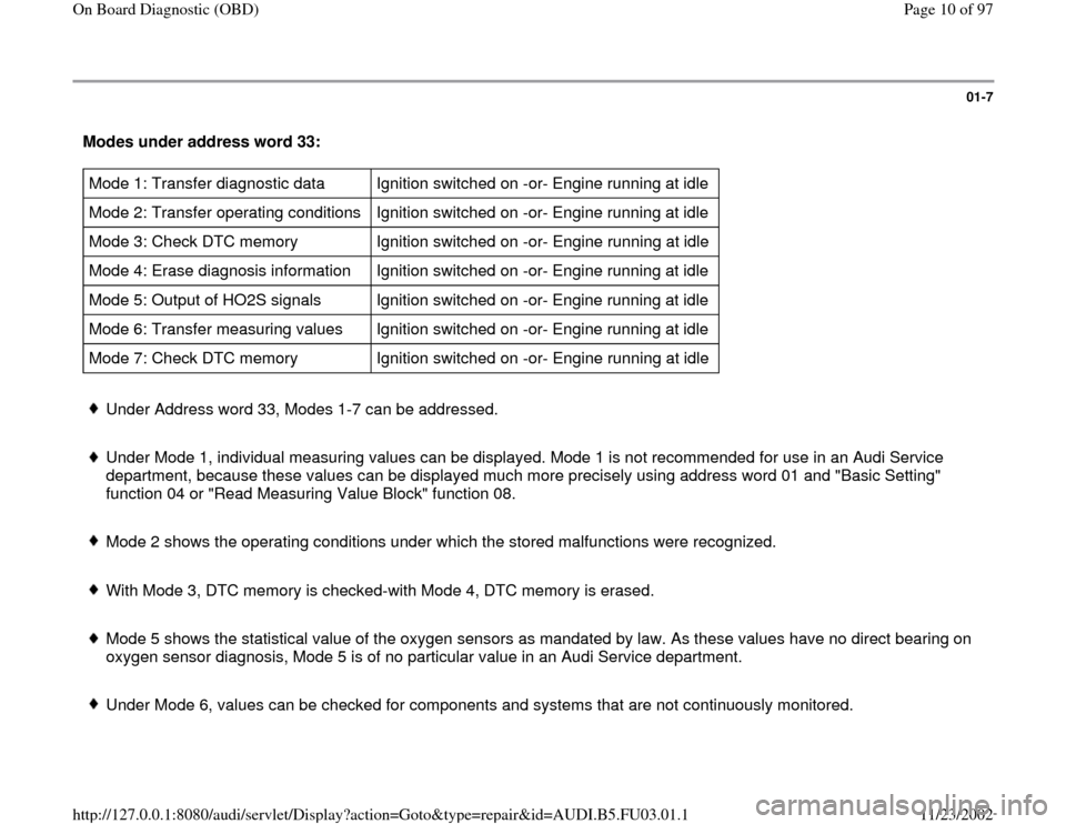
Modes under address word 33: Mode 1: Transfer diagnostic data Ignition switched on -or- Engine running at idle
Mode 2: Transfer operating conditions Ignition switched on -or- Engine running at idle
Mode 3: Check DTC memory Ignition switched on -or- Engine running at idle
Mode 4: Erase diagnosis information Ignition switched on -or- Engine running at idle
Mode 5: Output of HO2S signals Ignition switched on -or- Engine running at idle
Mode 6: Transfer measuring values Ignition switched on -or- Engine running at idle
Mode 7: Check DTC memory Ignition switched on -or- Engine running at idle Under Address word 33, Modes 1-7 can be addressed.
Under Mode 1, individual measuring values can be displayed. Mode 1 is not recommended for use in an Audi Service
department, because these values can be displayed much more precisely using address word 01 and "Basic Setting"
function 04 or "Read Measuring Value Block" function 08.
Mode 2 shows the operating conditions under which the stored malfunctions were recognized.
With Mode 3, DTC memory is checked-with Mode 4, DTC memory is erased.
Mode 5 shows the statistical value of the oxygen sensors as mandated by law. As these values have no direct bearing on
oxygen sensor diagnosis, Mode 5 is of no particular value in an Audi Service department.
Under Mode 6, values can be checked for components and systems that are not continuously monitored.
Pa
ge 10 of 97 On Board Dia
gnostic
(OBD
)
11/23/2002 htt
p://127.0.0.1:8080/audi/servlet/Dis
play?action=Goto&t
yp
e=re
pair&id=AUDI.B5.FU03.01.1
Page 11 of 97
With Mode 7 all malfunctions can be checked, even if they have not switched on the Malfunction Indicator Lamp (MIL) (if
the MIL has not been switched on, there is no malfunction recognized under Mode 3)
Pa
ge 11 of 97 On Board Dia
gnostic
(OBD
)
11/23/2002 htt
p://127.0.0.1:8080/audi/servlet/Dis
play?action=Goto&t
yp
e=re
pair&id=AUDI.B5.FU03.01.1
Page 14 of 97
01-9
Connecting
Notes:
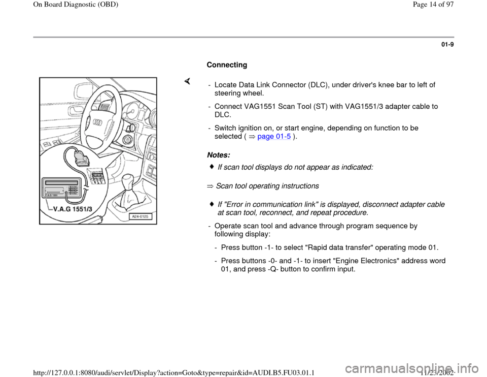
Scan tool operating instructions - Locate Data Link Connector (DLC), under driver's knee bar to left of
steering wheel.
- Connect VAG1551 Scan Tool (ST) with VAG1551/3 adapter cable to
DLC.
- Switch ignition on, or start engine, depending on function to be
selected ( page 01
-5 ).
If scan tool displays do not appear as indicated:If "Error in communication link" is displayed, disconnect adapter cable
at scan tool, reconnect, and repeat procedure.
- Operate scan tool and advance through program sequence by
following display:
- Press button -1- to select "Rapid data transfer" operating mode 01.
- Press buttons -0- and -1- to insert "Engine Electronics" address word
01, and press -Q- button to confirm input.
Pa
ge 14 of 97 On Board Dia
gnostic
(OBD
)
11/23/2002 htt
p://127.0.0.1:8080/audi/servlet/Dis
play?action=Goto&t
yp
e=re
pair&id=AUDI.B5.FU03.01.1
Page 56 of 97
01-42
Diagnostic Trouble
Code (DTC)
Malfunction text
MIL
Corrective action
SAE
VAG
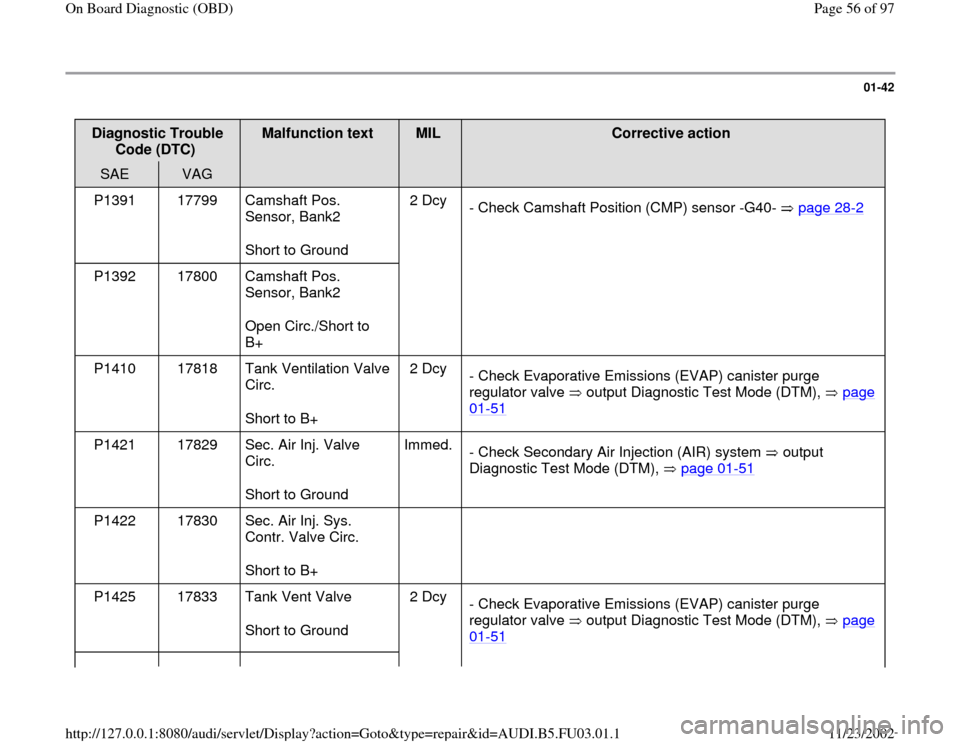
P1391 17799 Camshaft Pos.
Sensor, Bank2
Short to Ground 2 Dcy
- Check Camshaft Position (CMP) sensor -G40- page 28
-2
P1392 17800 Camshaft Pos.
Sensor, Bank2
Open Circ./Short to
B+
P1410 17818 Tank Ventilation Valve
Circ.
Short to B+ 2 Dcy
- Check Evaporative Emissions (EVAP) canister purge
regulator valve output Diagnostic Test Mode (DTM), page
01
-51
P1421 17829 Sec. Air Inj. Valve
Circ.
Short to Ground Immed.
- Check Secondary Air Injection (AIR) system output
Diagnostic Test Mode (DTM), page 01
-51
P1422 17830 Sec. Air Inj. Sys.
Contr. Valve Circ.
Short to B+
P1425 17833 Tank Vent Valve
Short to Ground 2 Dcy
- Check Evaporative Emissions (EVAP) canister purge
regulator valve output Diagnostic Test Mode (DTM), page
01
-51
Pa
ge 56 of 97 On Board Dia
gnostic
(OBD
)
11/23/2002 htt
p://127.0.0.1:8080/audi/servlet/Dis
play?action=Goto&t
yp
e=re
pair&id=AUDI.B5.FU03.01.1
Page 58 of 97
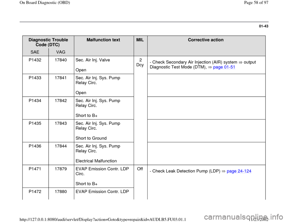
01-43
Diagnostic Trouble
Code (DTC)
Malfunction text
MIL
Corrective action
SAE
VAG
P1432 17840 Sec. Air Inj. Valve
Open 2
Dcy - Check Secondary Air Injection (AIR) system output
Diagnostic Test Mode (DTM), page 01
-51
P1433 17841 Sec. Air Inj. Sys. Pump
Relay Circ.
Open
P1434 17842 Sec. Air Inj. Sys. Pump
Relay Circ.
Short to B+
P1435 17843 Sec. Air Inj. Sys. Pump
Relay Circ.
Short to Ground
P1436 17844 Sec. Air Inj. Sys. Pump
Relay Circ.
Electrical Malfunction
P1471 17879 EVAP Emission Contr. LDP
Circ.
Short to B+ Off
- Check Leak Detection Pump (LDP) page 24
-124
P1472 17880 EVAP Emission Contr. LDP
Pa
ge 58 of 97 On Board Dia
gnostic
(OBD
)
11/23/2002 htt
p://127.0.0.1:8080/audi/servlet/Dis
play?action=Goto&t
yp
e=re
pair&id=AUDI.B5.FU03.01.1
Page 69 of 97
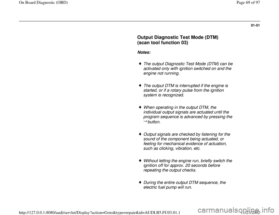
01-51
Output Diagnostic Test Mode (DTM)
(scan tool function 03)
Notes:
The output Diagnostic Test Mode (DTM) can be
activated only with ignition switched on and the
engine not running.
The output DTM is interrupted if the engine is
started, or if a rotary pulse from the ignition
system is recognized.
When operating in the output DTM, the
individual output signals are actuated until the
program sequence is advanced by pressing the
button.
Output signals are checked by listening for the
sound of the component being actuated, or
feeling for mechanical evidence of actuation,
such as clicking, vibration, etc.
Without letting the engine run, briefly switch the
ignition off for approx. 20 seconds before
repeating the output checks.
During the entire output DTM sequence, the
electric fuel pump will run.
Pa
ge 69 of 97 On Board Dia
gnostic
(OBD
)
11/23/2002 htt
p://127.0.0.1:8080/audi/servlet/Dis
play?action=Goto&t
yp
e=re
pair&id=AUDI.B5.FU03.01.1
Page 75 of 97
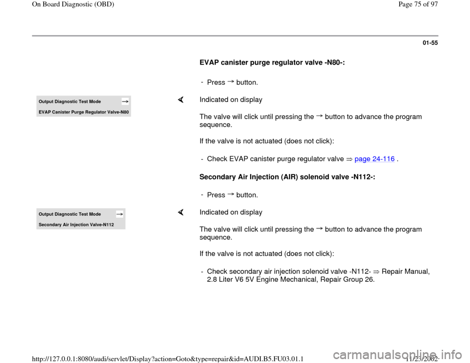
01-55
EVAP canister purge regulator valve -N80-:
-
Press button.Output Diagnostic Test Mode EVAP Canister Pur
ge Re
gulator Valve-N80
Indicated on display
The valve will click until pressing the button to advance the program
sequence.
If the valve is not actuated (does not click):
Secondary Air Injection (AIR) solenoid valve -N112-: - Check EVAP canister purge regulator valve page 24
-116
.
-
Press button.
Output Diagnostic Test Mode Secondar
y Air In
jection Valve-N112
Indicated on display
The valve will click until pressing the button to advance the program
sequence.
If the valve is not actuated (does not click): - Check secondary air injection solenoid valve -N112- Repair Manual,
2.8 Liter V6 5V Engine Mechanical, Repair Group 26.
Pa
ge 75 of 97 On Board Dia
gnostic
(OBD
)
11/23/2002 htt
p://127.0.0.1:8080/audi/servlet/Dis
play?action=Goto&t
yp
e=re
pair&id=AUDI.B5.FU03.01.1
Page 76 of 97
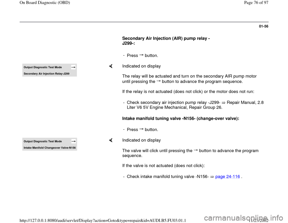
01-56
Secondary Air Injection (AIR) pump relay -
J299-:
-
Press button.Output Diagnostic Test Mode Secondary Air Injection Relay-J299
Indicated on display
The relay will be actuated and turn on the secondary AIR pump motor
until pressing the button to advance the program sequence.
If the relay is not actuated (does not click) or the motor does not run:
Intake manifold tuning valve -N156- (change-over valve): - Check secondary air injection pump relay -J299- Repair Manual, 2.8
Liter V6 5V Engine Mechanical, Repair Group 26. -
Press button.
Output Diagnostic Test Mode Intake Manifold Changeover Valve-N156
Indicated on display
The valve will click until pressing the button to advance the program
sequence.
If the valve is not actuated (does not click): - Check intake manifold tuning valve -N156- page 24
-116
.
Pa
ge 76 of 97 On Board Dia
gnostic
(OBD
)
11/23/2002 htt
p://127.0.0.1:8080/audi/servlet/Dis
play?action=Goto&t
yp
e=re
pair&id=AUDI.B5.FU03.01.1
Page 77 of 97
01-57
Valves -1- and -2- for camshaft adjustment, -
N205-, -N208-:
-
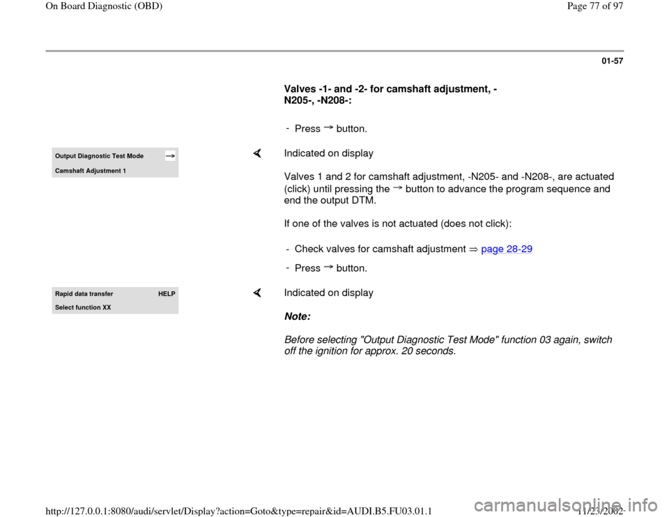
Press button.Output Diagnostic Test Mode Camshaft Adjustment 1
Indicated on display
Valves 1 and 2 for camshaft adjustment, -N205- and -N208-, are actuated
(click) until pressing the button to advance the program sequence and
end the output DTM.
If one of the valves is not actuated (does not click): - Check valves for camshaft adjustment page 28
-29
-
Press button.
Rapid data transfer
HELP
Select function XX
Indicated on display
Note:
Before selecting "Output Diagnostic Test Mode" function 03 again, switch
off the ignition for approx. 20 seconds.
Pa
ge 77 of 97 On Board Dia
gnostic
(OBD
)
11/23/2002 htt
p://127.0.0.1:8080/audi/servlet/Dis
play?action=Goto&t
yp
e=re
pair&id=AUDI.B5.FU03.01.1
Page 91 of 97
01-66
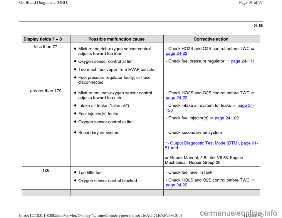
Display fields 7 + 8
Possible malfunction cause
Corrective action
less than 77
Mixture too rich-oxygen sensor control
adjusts toward too lean
Oxygen sensor control at limit
Too much fuel vapor from EVAP canister
Fuel pressure regulator faulty, or hose
disconnected - Check HO2S and O2S control before TWC
page 24
-22
- Check fuel pressure regulator page 24
-111
greater than 179
Mixture too lean-oxygen sensor control
adjusts toward too rich
Intake air leaks ("false air")
Fuel injector(s) faulty
Oxygen sensor control at limit- Check HO2S and O2S control before TWC
page 24
-22
- Check intake air system for leaks page 24
-
126
- Check fuel injector(s) page 24
-102
Secondary air system
Output Diagnostic Test Mode (DTM), page 01
-
51
and
Repair Manual, 2.8 Liter V6 5V Engine
Mechanical, Repair Group 26 - Check secondary air system
128
Too little fuel
Oxygen sensor control blocked- Check fuel level in tank
- Check HO2S and O2S control before TWC
page 24
-22
Pa
ge 91 of 97 On Board Dia
gnostic
(OBD
)
11/23/2002 htt
p://127.0.0.1:8080/audi/servlet/Dis
play?action=Goto&t
yp
e=re
pair&id=AUDI.B5.FU03.01.1