AUDI A8 1995 D2 / 1.G ATQ Engine Additional Signals Testing Owner's Manual
Manufacturer: AUDI, Model Year: 1995,
Model line: A8,
Model: AUDI A8 1995 D2 / 1.G
Pages: 44, PDF Size: 0.19 MB
AUDI A8 1995 D2 / 1.G ATQ Engine Additional Signals Testing Owner's Manual
A8 1995 D2 / 1.G
AUDI
AUDI
https://www.carmanualsonline.info/img/6/1057/w960_1057-0.png
AUDI A8 1995 D2 / 1.G ATQ Engine Additional Signals Testing Owner's Manual
Trending: fuel, air conditioning, diagram, buttons, fuse, ECU, wiring
Page 21 of 44
24-181
If specified values are not obtained:
- Check adjustment of switch or
- Replace brake light switch / brake pedal
switch.
If specified values are obtained:
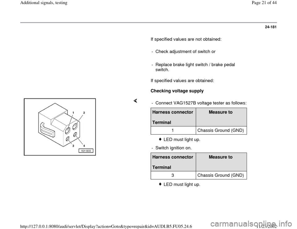
Checking voltage supply
- Connect VAG1527B voltage tester as follows:Harness connector
Terminal
Measure to
1 Chassis Ground (GND)
LED must light up.
- Switch ignition on.
Harness connector
Terminal
Measure to
3 Chassis Ground (GND)
LED must light up.
Pa
ge 21 of 44 Additional si
gnals, testin
g
11/23/2002 htt
p://127.0.0.1:8080/audi/servlet/Dis
play?action=Goto&t
yp
e=re
pair&id=AUDI.B5.FU05.24.6
Page 22 of 44
24-182
If LED does not light up:
- Check wire connection from terminal 1 or 3 of
connector for open circuit and short circuit to
Ground (GND):
Electrical Wiring Diagrams, Troubleshooting &
Component Locations binder
- Repair open circuit or short circuit if
necessary.
If LED lights up:
Checking activation
- Connect VAG1598/31 test box at wiring harness
to ECM, do not connect ECM Page 24
-17
.
- Check the following wire connections for open
circuit and short circuit to Ground (GND) and B+:
Harness connector
Terminal
VAG1598/31 test box
Socket
2 56
4 55
Pa
ge 22 of 44 Additional si
gnals, testin
g
11/23/2002 htt
p://127.0.0.1:8080/audi/servlet/Dis
play?action=Goto&t
yp
e=re
pair&id=AUDI.B5.FU05.24.6
Page 23 of 44
- Repair open circuit or short circuit if
necessary.
Pa
ge 23 of 44 Additional si
gnals, testin
g
11/23/2002 htt
p://127.0.0.1:8080/audi/servlet/Dis
play?action=Goto&t
yp
e=re
pair&id=AUDI.B5.FU05.24.6
Page 24 of 44
24-183
Clutch vacuum vent valve switch -F36-,
checking
Note:
This signal helps prevent excessive RPM
oscillations and tip-in shocks when clutch is
disengaged and is required for the cruise control
system.
Test sequence
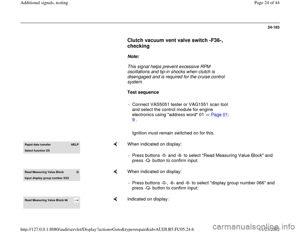
- Connect VAS5051 tester or VAG1551 scan tool
and select the control module for engine
electronics using "address word" 01 Page 01
-
9 .
Ignition must remain switched on for this.Rapid data transfer
HELP
Select function XX
When indicated on display:
- Press buttons -0- and -8- to select "Read Measuring Value Block" and
press -Q- button to confirm input.
Read Measurin
g Value Block
Q
Input displa
y group number XXX
When indicated on display:
- Press buttons -0-, -6- and -6- to select "display group number 066" and
press -Q- button to confirm input.
Read Measuring Value Block 66
Indicated on display:
Pa
ge 24 of 44 Additional si
gnals, testin
g
11/23/2002 htt
p://127.0.0.1:8080/audi/servlet/Dis
play?action=Goto&t
yp
e=re
pair&id=AUDI.B5.FU05.24.6
Page 25 of 44
1
2
3
4
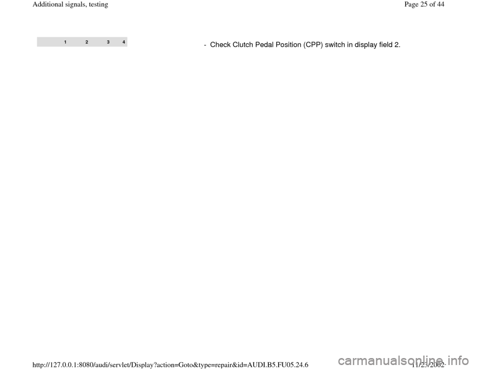
- Check Clutch Pedal Position (CPP) switch in display field 2.
Pa
ge 25 of 44 Additional si
gnals, testin
g
11/23/2002 htt
p://127.0.0.1:8080/audi/servlet/Dis
play?action=Goto&t
yp
e=re
pair&id=AUDI.B5.FU05.24.6
Page 26 of 44
24-184
Display fields
1 2 3 4
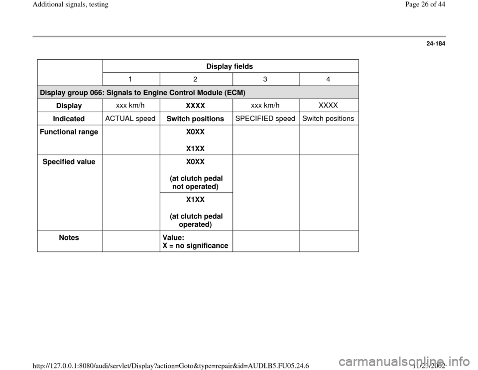
Display group 066: Signals to Engine Control Module (ECM)
Display xxx km/h
XXXX xxx km/h XXXX
Indicated ACTUAL speed
Switch positions SPECIFIED speed Switch positions
Functional range
X0XX
X1XX
Specified value
X0XX
(at clutch pedal
not operated)
X1XX
(at clutch pedal
operated)
Notes
Value:
X = no significance
Pa
ge 26 of 44 Additional si
gnals, testin
g
11/23/2002 htt
p://127.0.0.1:8080/audi/servlet/Dis
play?action=Goto&t
yp
e=re
pair&id=AUDI.B5.FU05.24.6
Page 27 of 44
24-185
If indications do not resemble description:
Check switch
- Remove driver-side storage compartment.
Repair Manual, Body
-Interior, Repair Group
68; Instrument Panel; Removing Driver
-Side
Storage Compartment
- Disconnect harness connector at Clutch Pedal
Position (CPP) switch.
Note:
Connector sockets are marked on the back side
of the connector.
- Connect multimeter between terminal 1 and 2
for resistance measurement.
Specification: approx. 0
- Depress clutch pedal.
Specification: (no continuity)
Pa
ge 27 of 44 Additional si
gnals, testin
g
11/23/2002 htt
p://127.0.0.1:8080/audi/servlet/Dis
play?action=Goto&t
yp
e=re
pair&id=AUDI.B5.FU05.24.6
Page 28 of 44
If specified value is not obtained:
- Check adjustment of switch or
- Replace Clutch Pedal Position (CPP) switch.
Pa
ge 28 of 44 Additional si
gnals, testin
g
11/23/2002 htt
p://127.0.0.1:8080/audi/servlet/Dis
play?action=Goto&t
yp
e=re
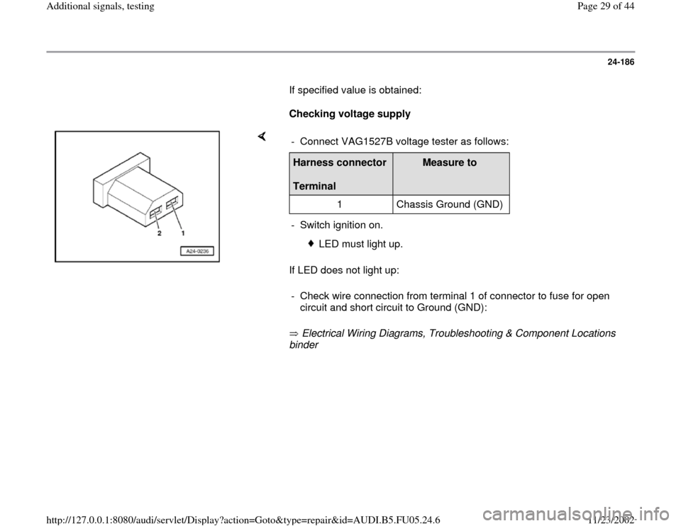
pair&id=AUDI.B5.FU05.24.6
Page 29 of 44
24-186
If specified value is obtained:
Checking voltage supply
If LED does not light up:
Electrical Wiring Diagrams, Troubleshooting & Component Locations
binder - Connect VAG1527B voltage tester as follows:Harness connector
Terminal
Measure to
1 Chassis Ground (GND)
- Switch ignition on.
LED must light up.
- Check wire connection from terminal 1 of connector to fuse for open
circuit and short circuit to Ground (GND):
Pa
ge 29 of 44 Additional si
gnals, testin
g
11/23/2002 htt
p://127.0.0.1:8080/audi/servlet/Dis
play?action=Goto&t
yp
e=re
pair&id=AUDI.B5.FU05.24.6
Page 30 of 44
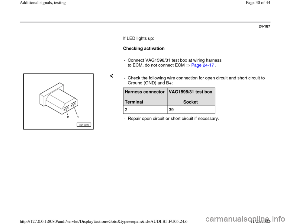
24-187
If LED lights up:
Checking activation
- Connect VAG1598/31 test box at wiring harness
to ECM, do not connect ECM Page 24
-17
.
- Check the following wire connection for open circuit and short circuit to
Ground (GND) and B+: Harness connector
Terminal
VAG1598/31 test box
Socket
2 39
- Repair open circuit or short circuit if necessary.
Pa
ge 30 of 44 Additional si
gnals, testin
g
11/23/2002 htt
p://127.0.0.1:8080/audi/servlet/Dis
play?action=Goto&t
yp
e=re
pair&id=AUDI.B5.FU05.24.6
Trending: ESP, turn signal, air conditioning, ABS, clutch, diagram, fuse diagram
