sensor AUDI A8 1996 D2 / 1.G 01V Transmission Read Measuring Value Block E 17 Workshop Manual
[x] Cancel search | Manufacturer: AUDI, Model Year: 1996, Model line: A8, Model: AUDI A8 1996 D2 / 1.GPages: 49, PDF Size: 0.16 MB
Page 3 of 49
01-189
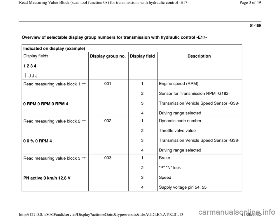
Overview of selectable display group numbers for transmission with hydraulic control -E17- Indicated on display (example)
Display fields:
1 2 3 4
J J J
Display group no.
Display field
Description
Read measuring value block 1
0 RPM 0 RPM 0 RPM 4
001 1
2
3
4 Engine speed (RPM)
Sensor for Transmission RPM -G182-
Transmission Vehicle Speed Sensor -G38-
Driving range selected
Read measuring value block 2
0 0 % 0 RPM 4 002 1
2
3
4 Dynamic code number
Throttle valve value
Transmission Vehicle Speed Sensor -G38-
Driving range selected
Read measuring value block 3
PN active 0 km/h 12.8 V 003 1
2
3
4 Brake
"P" "N" lock
Speed
Supply voltage pin 54, 55
Pa
ge 3 of 49 Read Measurin
g Value Block
(scan tool function 08
) for transmissions with h
ydraulic control -E17-
11/20/2002 htt
p://127.0.0.1:8080/audi/servlet/Dis
play?action=Goto&t
yp
e=re
pair&id=AUDI.B5.AT02.01.13
Page 11 of 49
01-194
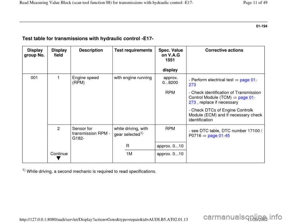
Test table for transmissions with hydraulic control -E17-
Display
group No. Display
field Description
Test requirements
Spec. Value
on V.A.G
1551
display Corrective actions
001
1 Engine speed
(RPM) with engine running approx.
0...8200
RPM - Perform electrical test page 01
-
273
- Check identification of Transmission
Control Module (TCM) page 01
-
273
, replace if necessary
- Check DTCs of Engine Controlk
Module (ECM) and if necessary check
identification
2 Sensor for
transmission RPM -
G182- while driving, with
gear selected
1) RPM
- see DTC table, DTC number 17100 /
P0716 page 01
-45
R
approx. 0...10
Continue
1M approx. 0...10
1) While driving, a second mechanic is required to read specifications.
Pa
ge 11 of 49 Read Measurin
g Value Block
(scan tool function 08
) for transmissions with h
ydraulic control -E17-
11/20/2002 htt
p://127.0.0.1:8080/audi/servlet/Dis
play?action=Goto&t
yp
e=re
pair&id=AUDI.B5.AT02.01.13
Page 12 of 49
01-195
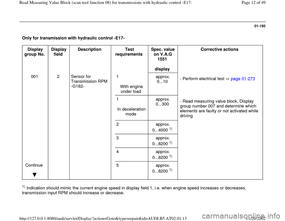
Only for transmission with hydraulic control -E17-
Display
group No. Display
field Description
Test
requirements Spec. value
on V.A.G
1551
display Corrective actions
001 2 Sensor for
Transmission RPM
-G182- 1
With engine
under load approx.
0...10 - Perform electrical test page 01
-273
1
In deceleration
mode approx.
0...300 - Read measuring value block, Display
group number 007 and determine which
elements are faulty or not activated while
driving
2 approx.
0...4000
1)
3 approx.
0...8200 1)
4 approx.
0...8200 1)
Continue
5 approx.
0...8200
1)
1) Indication should mimic the current engine speed in display field 1, i.e. when engine speed increases or decreases,
transmission input RPM should increase or decrease.
Pa
ge 12 of 49 Read Measurin
g Value Block
(scan tool function 08
) for transmissions with h
ydraulic control -E17-
11/20/2002 htt
p://127.0.0.1:8080/audi/servlet/Dis
play?action=Goto&t
yp
e=re
pair&id=AUDI.B5.AT02.01.13
Page 13 of 49
01-196
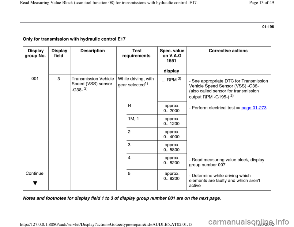
Only for transmission with hydraulic control E17
Display
group No. Display
field Description
Test
requirements Spec. value
on V.A.G
1551
display Corrective actions
001
3 Transmission Vehicle
Speed (VSS) sensor
-G38-
2) While driving, with
gear selected
1) ... RPM
3)
- See appropriate DTC for Transmission
Vehicle Speed Sensor (VSS) -G38-
(also called sensor for transmission
output RPM -G195-)
2)
R
approx.
0...2000 - Perform electrical test page 01
-273
1M, 1 approx.
0...1200
2 approx.
0...4000
3 approx.
0...5800
4 approx.
0...8200 - Read measuring value block, display
group number 007
Continue
5 approx.
0...8200 - Determine while driving which
elements are faulty and which aren't
active
Notes and footnotes for display field 1 to 3 of display group number 001 are on the next page.
Pa
ge 13 of 49 Read Measurin
g Value Block
(scan tool function 08
) for transmissions with h
ydraulic control -E17-
11/20/2002 htt
p://127.0.0.1:8080/audi/servlet/Dis
play?action=Goto&t
yp
e=re
pair&id=AUDI.B5.AT02.01.13
Page 14 of 49
01-197
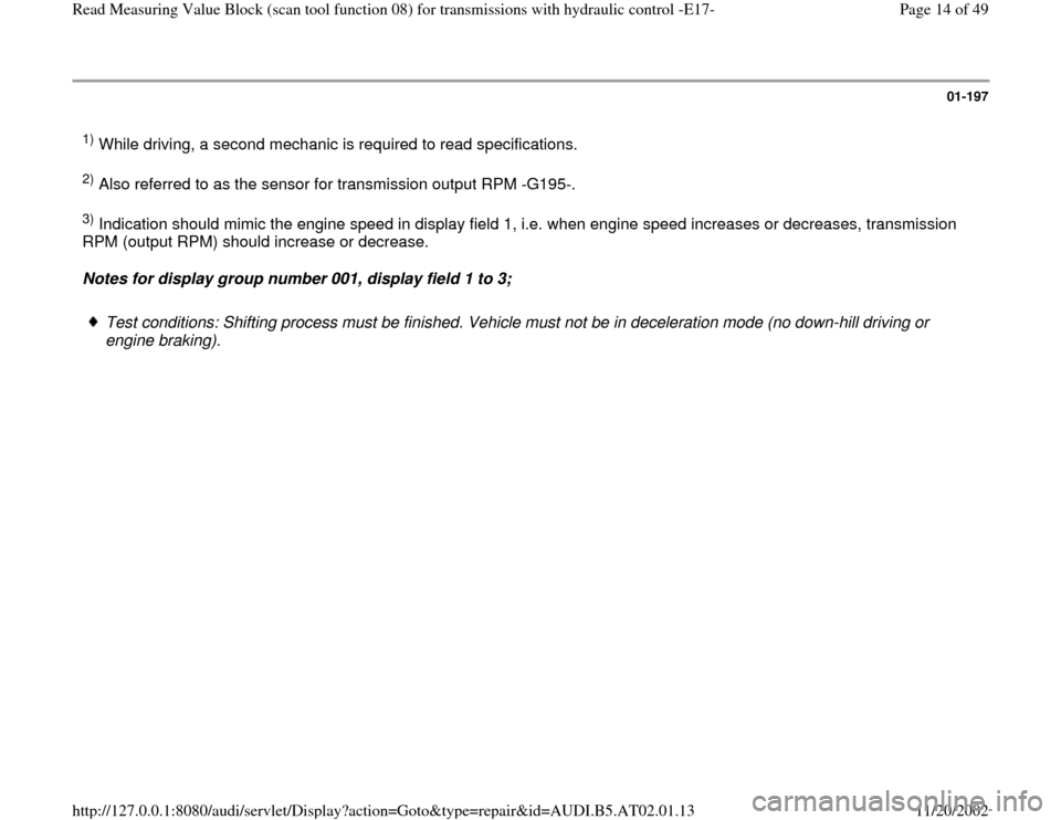
1) While driving, a second mechanic is required to read specifications. 2) Also referred to as the sensor for transmission output RPM -G195-. 3) Indication should mimic the engine speed in display field 1, i.e. when engine speed increases or decreases, transmission
RPM (output RPM) should increase or decrease.
Notes for display group number 001, display field 1 to 3;
Test conditions: Shifting process must be finished. Vehicle must not be in deceleration mode (no down-hill driving or
engine braking).
Pa
ge 14 of 49 Read Measurin
g Value Block
(scan tool function 08
) for transmissions with h
ydraulic control -E17-
11/20/2002 htt
p://127.0.0.1:8080/audi/servlet/Dis
play?action=Goto&t
yp
e=re
pair&id=AUDI.B5.AT02.01.13
Page 19 of 49
01-201
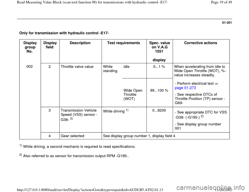
Only for transmission with hydraulic control -E17-
Display
group
No. Display
field Description
Test requirements
Spec. value
on V.A.G
1551
display Corrective actions
002
2 Throttle valve value While
standing idle 0...1 % When accelerating from idle to
Wide Open Throttle (WOT), %-
value increases steadily.
Wide Open
Throttle
(WOT)
99...100 % - Perform electrical test
page 01
-273
- See respective DTCs of
Throttle Position (TP) sensor -
G69-
3 Transmission Vehicle
Speed (VSS) sensor -
G38-
2) While driving
1)
0...8200
- See appropriate DTC for VSS
-G38- (-G195-)
2)
- See display group number
001
4 Gear selected See display group number 1, display field 4
1) While driving, a second mechanic is required to read specifications. 2) Also referred to as sensor for transmission output RPM -G195-.
Pa
ge 19 of 49 Read Measurin
g Value Block
(scan tool function 08
) for transmissions with h
ydraulic control -E17-
11/20/2002 htt
p://127.0.0.1:8080/audi/servlet/Dis
play?action=Goto&t
yp
e=re
pair&id=AUDI.B5.AT02.01.13
Page 20 of 49
01-202
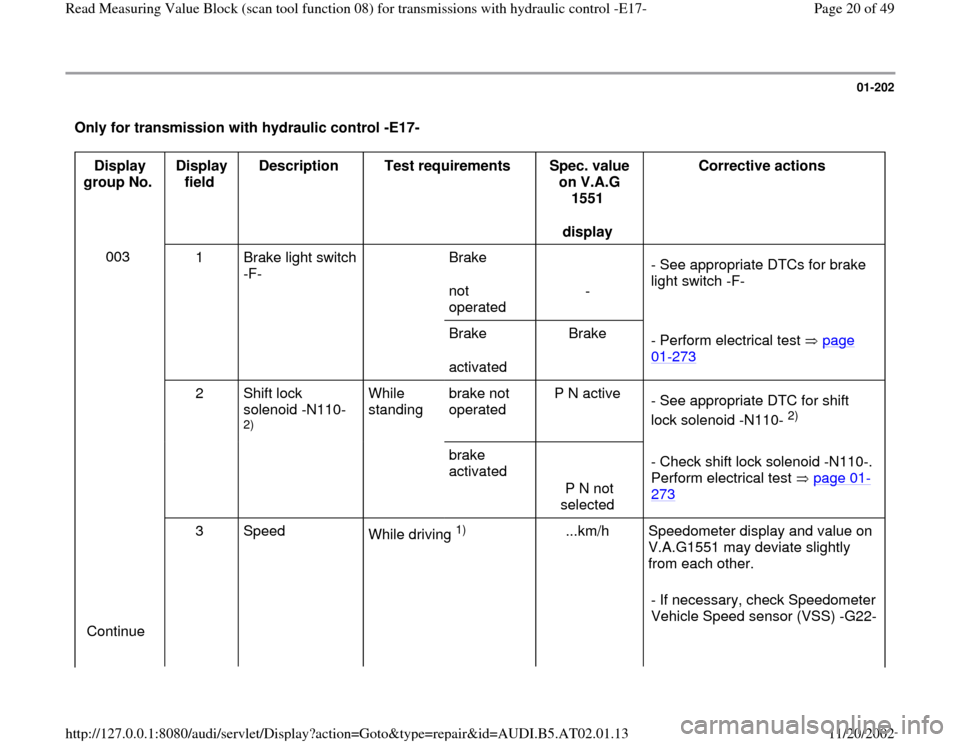
Only for transmission with hydraulic control -E17-
Display
group No. Display
field Description
Test requirements
Spec. value
on V.A.G
1551
display Corrective actions
003
1 Brake light switch
-F- Brake
not
operated
- - See appropriate DTCs for brake
light switch -F-
Brake
activated Brake
- Perform electrical test page
01
-273
2 Shift lock
solenoid -N110-
2) While
standing brake not
operated P N active
- See appropriate DTC for shift
lock solenoid -N110-
2)
brake
activated
P N not
selected - Check shift lock solenoid -N110-.
Perform electrical test page 01
-
273
Continue 3 Speed
While driving
1)
...km/h Speedometer display and value on
V.A.G1551 may deviate slightly
from each other.
- If necessary, check Speedometer
Vehicle Speed sensor (VSS) -G22-
Pa
ge 20 of 49 Read Measurin
g Value Block
(scan tool function 08
) for transmissions with h
ydraulic control -E17-
11/20/2002 htt
p://127.0.0.1:8080/audi/servlet/Dis
play?action=Goto&t
yp
e=re
pair&id=AUDI.B5.AT02.01.13
Page 22 of 49
01-203
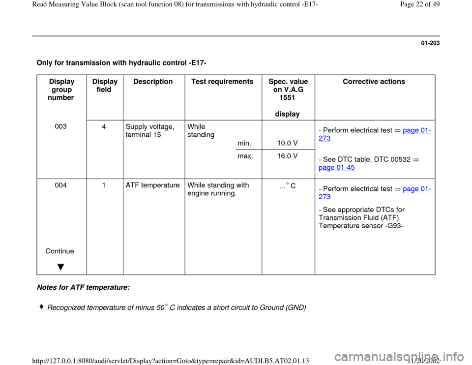
Only for transmission with hydraulic control -E17-
Display
group
number Display
field Description
Test requirements
Spec. value
on V.A.G
1551
display Corrective actions
003
4 Supply voltage,
terminal 15 While
standing
min.
10.0 V - Perform electrical test page 01
-
273
max. 16.0 V
- See DTC table, DTC 00532
page 01
-45
004
Continue
1 ATF temperature
While standing with
engine running. ... C
- Perform electrical test page 01
-
273
- See appropriate DTCs for
Transmission Fluid (ATF)
Temperature sensor -G93-
Notes for ATF temperature:
Recognized temperature of minus 50 C indicates a short circuit to Ground (GND)
Pa
ge 22 of 49 Read Measurin
g Value Block
(scan tool function 08
) for transmissions with h
ydraulic control -E17-
11/20/2002 htt
p://127.0.0.1:8080/audi/servlet/Dis
play?action=Goto&t
yp
e=re
pair&id=AUDI.B5.AT02.01.13
Page 35 of 49
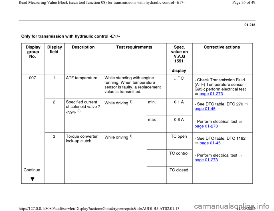
01-215
Only for transmission with hydraulic control -E17-
Display
group
No. Display
field Description
Test requirements
Spec.
value on
V.A.G
1551
display Corrective actions
007 1 ATF temperature
While standing with engine
running. When temperature
sensor is faulty, a replacement
value is transmitted. ... C
- Check Transmission Fluid
(ATF) Temperature sensor -
G93-; perform electrical test
page 01
-273
2 Specified current
of solenoid valve 7
-N94-
2) While driving
1)
min. 0.1 A
- See DTC table, DTC 270
page 01
-45
max 0.8 A
- Perform electrical test
page 01
-273
3 Torque converter
lock-up clutch While driving
1)
TC open
- See DTC table, DTC 1192
page 01
-45
TC control
- Perform electrical test
page 01
-273
Continue
TC closed
Pa
ge 35 of 49 Read Measurin
g Value Block
(scan tool function 08
) for transmissions with h
ydraulic control -E17-
11/20/2002 htt
p://127.0.0.1:8080/audi/servlet/Dis
play?action=Goto&t
yp
e=re
pair&id=AUDI.B5.AT02.01.13