air condition AUDI A8 1996 D2 / 1.G AHA Engine On Board Diagnostic Workshop Manual
[x] Cancel search | Manufacturer: AUDI, Model Year: 1996, Model line: A8, Model: AUDI A8 1996 D2 / 1.GPages: 97, PDF Size: 0.31 MB
Page 8 of 97
01-5
On Board Diagnostic (OBD) technical data
Memory
Temporary memory and permanent memory. If the engine control module is disconnected from the Battery Positive
Voltage (B+) supply, the readiness code and learning values will be erased. Any malfunctions stored in DTC memory are
not erased.
Data output
Rapid data transfer
Additional malfunction indication by Malfunction Indicator Lamp (MIL) lighting up
ECM identification
page 01
-8 ; VAG1551 Scan Tool (ST), connecting and selecting "Engine Electronics" address word 01
ECM functions
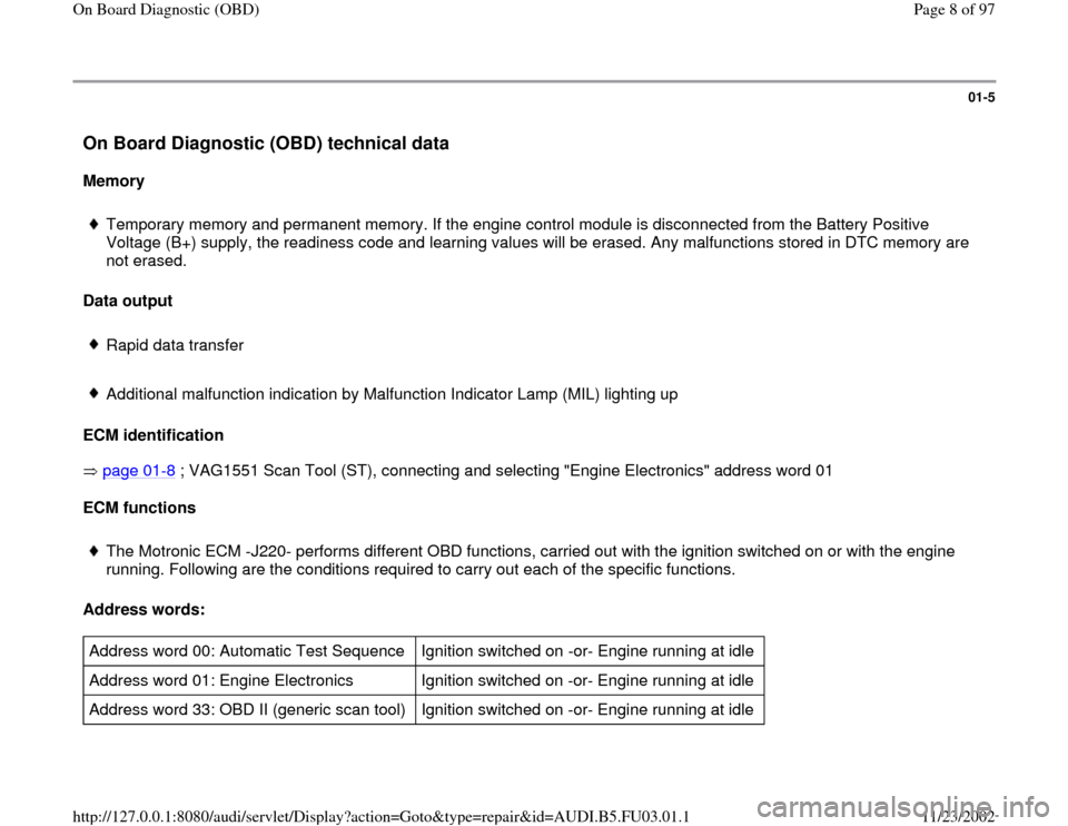
The Motronic ECM -J220- performs different OBD functions, carried out with the ignition switched on or with the engine
running. Following are the conditions required to carry out each of the specific functions.
Address words:
Address word 00: Automatic Test Sequence Ignition switched on -or- Engine running at idle
Address word 01: Engine Electronics Ignition switched on -or- Engine running at idle
Address word 33: OBD II (generic scan tool) Ignition switched on -or- Engine running at idle
Pa
ge 8 of 97 On Board Dia
gnostic
(OBD
)
11/23/2002 htt
p://127.0.0.1:8080/audi/servlet/Dis
play?action=Goto&t
yp
e=re
pair&id=AUDI.B5.FU03.01.1
Page 10 of 97
01-7
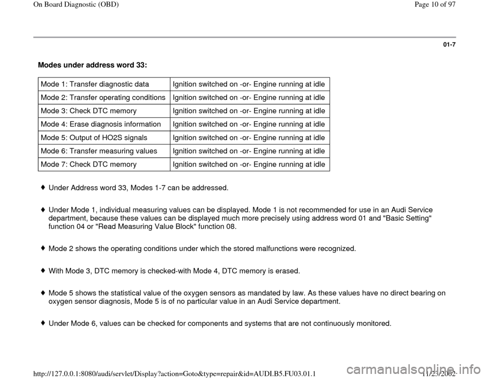
Modes under address word 33: Mode 1: Transfer diagnostic data Ignition switched on -or- Engine running at idle
Mode 2: Transfer operating conditions Ignition switched on -or- Engine running at idle
Mode 3: Check DTC memory Ignition switched on -or- Engine running at idle
Mode 4: Erase diagnosis information Ignition switched on -or- Engine running at idle
Mode 5: Output of HO2S signals Ignition switched on -or- Engine running at idle
Mode 6: Transfer measuring values Ignition switched on -or- Engine running at idle
Mode 7: Check DTC memory Ignition switched on -or- Engine running at idle Under Address word 33, Modes 1-7 can be addressed.
Under Mode 1, individual measuring values can be displayed. Mode 1 is not recommended for use in an Audi Service
department, because these values can be displayed much more precisely using address word 01 and "Basic Setting"
function 04 or "Read Measuring Value Block" function 08.
Mode 2 shows the operating conditions under which the stored malfunctions were recognized.
With Mode 3, DTC memory is checked-with Mode 4, DTC memory is erased.
Mode 5 shows the statistical value of the oxygen sensors as mandated by law. As these values have no direct bearing on
oxygen sensor diagnosis, Mode 5 is of no particular value in an Audi Service department.
Under Mode 6, values can be checked for components and systems that are not continuously monitored.
Pa
ge 10 of 97 On Board Dia
gnostic
(OBD
)
11/23/2002 htt
p://127.0.0.1:8080/audi/servlet/Dis
play?action=Goto&t
yp
e=re
pair&id=AUDI.B5.FU03.01.1
Page 24 of 97
01-18
Diagnostic Trouble Code (DTC) table
Notes:
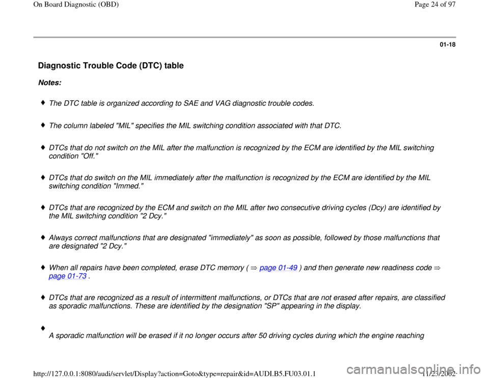
The DTC table is organized according to SAE and VAG diagnostic trouble codes.
The column labeled "MIL" specifies the MIL switching condition associated with that DTC.
DTCs that do not switch on the MIL after the malfunction is recognized by the ECM are identified by the MIL switching
condition "Off."
DTCs that do switch on the MIL immediately after the malfunction is recognized by the ECM are identified by the MIL
switching condition "Immed."
DTCs that are recognized by the ECM and switch on the MIL after two consecutive driving cycles (Dcy) are identified by
the MIL switching condition "2 Dcy."
Always correct malfunctions that are designated "immediately" as soon as possible, followed by those malfunctions that
are designated "2 Dcy."
When all repairs have been completed, erase DTC memory ( page 01
-49
) and then generate new readiness code
page 01
-73
.
DTCs that are recognized as a result of intermittent malfunctions, or DTCs that are not erased after repairs, are classified
as sporadic malfunctions. These are identified by the designation "SP" appearing in the display.
A sporadic malfunction will be erased if it no longer occurs after 50 driving cycles during which the engine reaching
Pa
ge 24 of 97 On Board Dia
gnostic
(OBD
)
11/23/2002 htt
p://127.0.0.1:8080/audi/servlet/Dis
play?action=Goto&t
yp
e=re
pair&id=AUDI.B5.FU03.01.1
Page 66 of 97
01-49
Erase DTC Memory (scan tool function
05)
Required special tools and test equipment
VAG1551 Scan Tool (ST) with VAG1551/3
adapter cable
Test condition
Malfunction(s) repaired
Note:
If DTC memory has been erased, generate new
readiness code page 01
-73
.
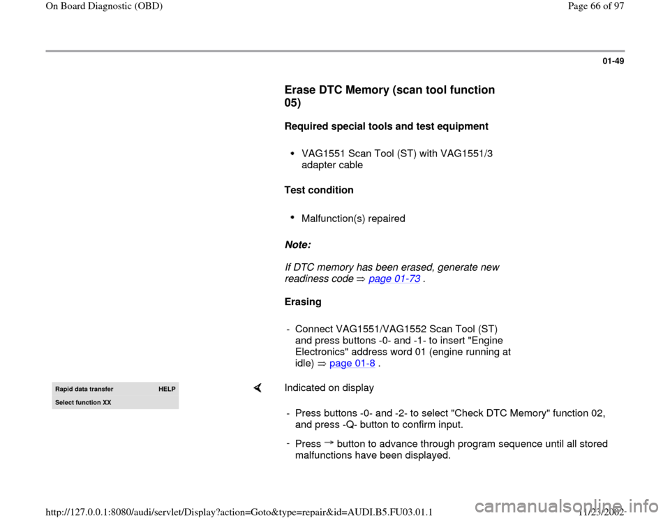
Erasing
- Connect VAG1551/VAG1552 Scan Tool (ST)
and press buttons -0- and -1- to insert "Engine
Electronics" address word 01 (engine running at
idle) page 01
-8 .
Rapid data transfer
HELP
Select function XX
Indicated on display
- Press buttons -0- and -2- to select "Check DTC Memory" function 02,
and press -Q- button to confirm input.
-
Press button to advance through program sequence until all stored
malfunctions have been displayed.
Pa
ge 66 of 97 On Board Dia
gnostic
(OBD
)
11/23/2002 htt
p://127.0.0.1:8080/audi/servlet/Dis
play?action=Goto&t
yp
e=re
pair&id=AUDI.B5.FU03.01.1
Page 71 of 97
01-52
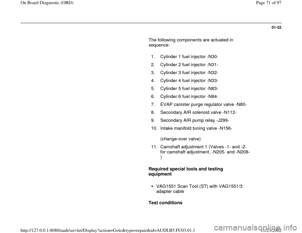
The following components are actuated in
sequence:
1. Cylinder 1 fuel injector -N30-
2. Cylinder 2 fuel injector -N31-
3. Cylinder 3 fuel injector -N32-
4. Cylinder 4 fuel injector -N33-
5. Cylinder 5 fuel injector -N83-
6. Cylinder 6 fuel injector -N84-
7. EVAP canister purge regulator valve -N80-
8. Secondary AIR solenoid valve -N112-
9. Secondary AIR pump relay -J299-
10.
Intake manifold tuning valve -N156-
(change-over valve)
11.
Camshaft adjustment 1 (Valves -1- and -2-
for camshaft adjustment, -N205- and -N208-
)
Required special tools and testing
equipment
VAG1551 Scan Tool (ST) with VAG1551/3
adapter cable
Test conditions
Pa
ge 71 of 97 On Board Dia
gnostic
(OBD
)
11/23/2002 htt
p://127.0.0.1:8080/audi/servlet/Dis
play?action=Goto&t
yp
e=re
pair&id=AUDI.B5.FU03.01.1