lock AUDI A8 1996 D2 / 1.G ATQ Engine Ignition System Checking Workshop Manual
[x] Cancel search | Manufacturer: AUDI, Model Year: 1996, Model line: A8, Model: AUDI A8 1996 D2 / 1.GPages: 65, PDF Size: 0.53 MB
Page 1 of 65
28-1
Ignition system, checking
General notes on ignition system
The battery should only be disconnected and
reconnected when the ignition is turned off,
since otherwise the Engine Control Module
(ECM) can be damaged.
The Engine Control Module (ECM) is equipped
with an On Board Diagnostic (OBD)
For the electric components to work properly, a
voltage of at least 12.7 V is required.
It is possible that the control module will
recognize a malfunction and store a DTC during
some tests. After completing all tests and
repairs, DTC memory should therefore be
checked and erased if necessary.
If the engine only starts briefly and then turns
off again after troubleshooting, repair or
checking of the components, it may be that the
immobilizer is blocking the Engine Control
Module (ECM). DTC memory must then be
checked and if necessary, control module must
be adapted.
Pa
ge 1 of 65 I
gnition s
ystem, checkin
g
11/23/2002 htt
p://127.0.0.1:8080/audi/servlet/Dis
play?action=Goto&t
yp
e=re
pair&id=AUDI.B5.FU05.28.1
Page 18 of 65
28-15
Component location Overview of Component
Locations, page Page 24
-5
Test sequence
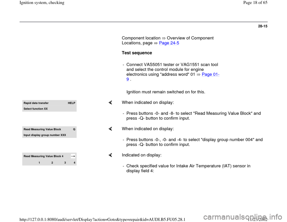
- Connect VAS5051 tester or VAG1551 scan tool
and select the control module for engine
electronics using "address word" 01 Page 01
-
9 .
Ignition must remain switched on for this.Rapid data transfer
HELP
Select function XX
When indicated on display:
- Press buttons -0- and -8- to select "Read Measuring Value Block" and
press -Q- button to confirm input.
Read Measurin
g Value Block
Q
Input display group number XXX
When indicated on display:
- Press buttons -0-, -0- and -4- to select "display group number 004" and
press -Q- button to confirm input.
Read Measuring Value Block 4
1
2
3
4
Indicated on display:
- Check specified value for Intake Air Temperature (IAT) sensor in
display field 4:
Pa
ge 18 of 65 I
gnition s
ystem, checkin
g
11/23/2002 htt
p://127.0.0.1:8080/audi/servlet/Dis
play?action=Goto&t
yp
e=re
pair&id=AUDI.B5.FU05.28.1
Page 27 of 65
28-24
Component location Overview of Component
Locations, page Page 24
-5
Test requirement:
Engine cold
Test sequence
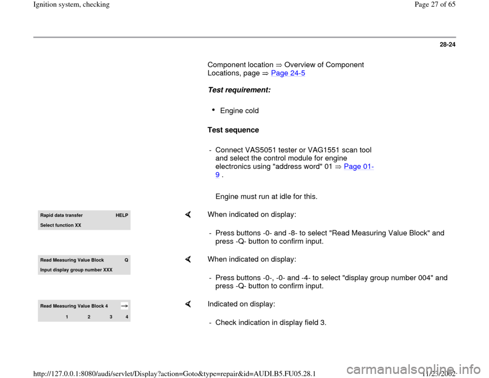
- Connect VAS5051 tester or VAG1551 scan tool
and select the control module for engine
electronics using "address word" 01 Page 01
-
9 .
Engine must run at idle for this.Rapid data transfer
HELP
Select function XX
When indicated on display:
- Press buttons -0- and -8- to select "Read Measuring Value Block" and
press -Q- button to confirm input.
Read Measurin
g Value Block
Q
Input display group number XXX
When indicated on display:
- Press buttons -0-, -0- and -4- to select "display group number 004" and
press -Q- button to confirm input.
Read Measuring Value Block 4
1
2
3
4
Indicated on display:
- Check indication in display field 3.
Pa
ge 27 of 65 I
gnition s
ystem, checkin
g
11/23/2002 htt
p://127.0.0.1:8080/audi/servlet/Dis
play?action=Goto&t
yp
e=re
pair&id=AUDI.B5.FU05.28.1
Page 39 of 65
28-34
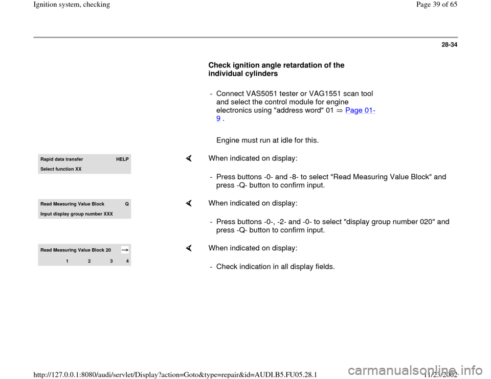
Check ignition angle retardation of the
individual cylinders
- Connect VAS5051 tester or VAG1551 scan tool
and select the control module for engine
electronics using "address word" 01 Page 01
-
9 .
Engine must run at idle for this.Rapid data transfer
HELP
Select function XX
When indicated on display:
- Press buttons -0- and -8- to select "Read Measuring Value Block" and
press -Q- button to confirm input.
Read Measuring Value Block
Q
Input displa
y group number XXX
When indicated on display:
- Press buttons -0-, -2- and -0- to select "display group number 020" and
press -Q- button to confirm input.
Read Measuring Value Block 20
1
2
3
4
When indicated on display:
- Check indication in all display fields.
Pa
ge 39 of 65 I
gnition s
ystem, checkin
g
11/23/2002 htt
p://127.0.0.1:8080/audi/servlet/Dis
play?action=Goto&t
yp
e=re
pair&id=AUDI.B5.FU05.28.1
Page 40 of 65
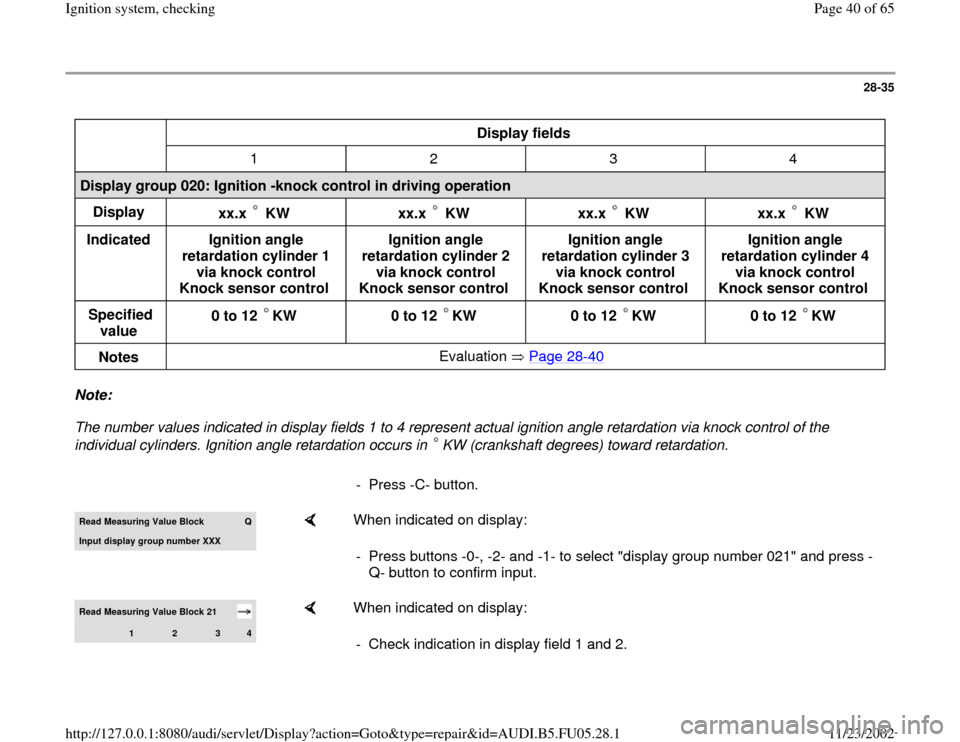
28-35
Display fields
1 2 3 4
Display group 020: Ignition -knock control in driving operation
Display
xx.x KW
xx.x KW
xx.x KW
xx.x KW
Indicated
Ignition angle
retardation cylinder 1
via knock control
Knock sensor control Ignition angle
retardation cylinder 2
via knock control
Knock sensor control Ignition angle
retardation cylinder 3
via knock control
Knock sensor control Ignition angle
retardation cylinder 4
via knock control
Knock sensor control
Specified
value 0 to 12 KW
0 to 12 KW
0 to 12 KW
0 to 12 KW
Notes Evaluation Page 28
-40
Note:
The number values indicated in display fields 1 to 4 represent actual ignition angle retardation via knock control of the
individual cylinders. Ignition angle retardation occurs in KW (crankshaft degrees) toward retardation.
- Press -C- button.Read Measuring Value Block
Q
Input display group number XXX
When indicated on display:
- Press buttons -0-, -2- and -1- to select "display group number 021" and press -
Q- button to confirm input.
Read Measuring Value Block 21
1
2
3
4
When indicated on display:
- Check indication in display field 1 and 2.
Pa
ge 40 of 65 I
gnition s
ystem, checkin
g
11/23/2002 htt
p://127.0.0.1:8080/audi/servlet/Dis
play?action=Goto&t
yp
e=re
pair&id=AUDI.B5.FU05.28.1
Page 41 of 65
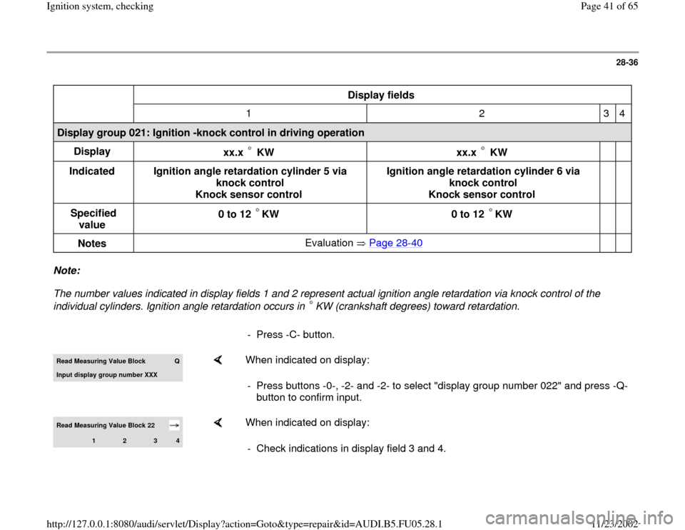
28-36
Display fields
1 2 3 4
Display group 021: Ignition -knock control in driving operation
Display
xx.x KW
xx.x KW
Indicated
Ignition angle retardation cylinder 5 via
knock control
Knock sensor control Ignition angle retardation cylinder 6 via
knock control
Knock sensor control
Specified
value 0 to 12 KW
0 to 12 KW
Notes Evaluation Page 28
-40
Note:
The number values indicated in display fields 1 and 2 represent actual ignition angle retardation via knock control of the
individual cylinders. Ignition angle retardation occurs in KW (crankshaft degrees) toward retardation.
- Press -C- button.Read Measurin
g Value Block
Q
Input displa
y group number XXX
When indicated on display:
- Press buttons -0-, -2- and -2- to select "display group number 022" and press -Q-
button to confirm input.
Read Measuring Value Block 22
1
2
3
4
When indicated on display:
- Check indications in display field 3 and 4.
Pa
ge 41 of 65 I
gnition s
ystem, checkin
g
11/23/2002 htt
p://127.0.0.1:8080/audi/servlet/Dis
play?action=Goto&t
yp
e=re
pair&id=AUDI.B5.FU05.28.1
Page 42 of 65
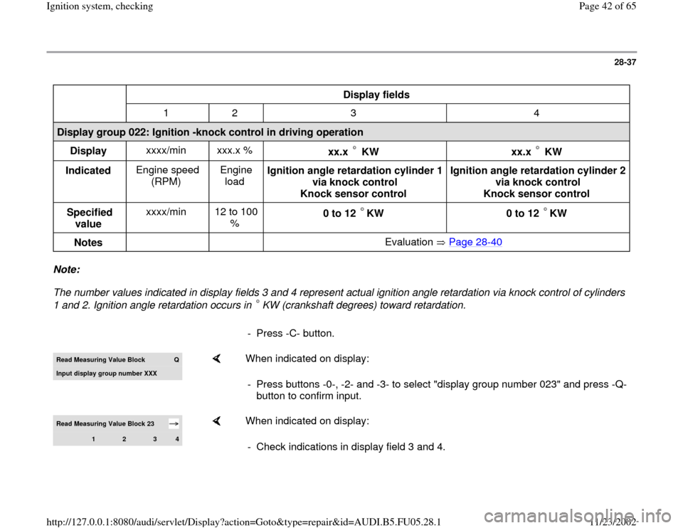
28-37
Display fields
1 2 3 4
Display group 022: Ignition -knock control in driving operation
Display xxxx/min xxx.x %
xx.x KW
xx.x KW
Indicated Engine speed
(RPM) Engine
load Ignition angle retardation cylinder 1
via knock control
Knock sensor control Ignition angle retardation cylinder 2
via knock control
Knock sensor control
Specified
value xxxx/min 12 to 100
% 0 to 12 KW
0 to 12 KW
Notes Evaluation Page 28
-40
Note:
The number values indicated in display fields 3 and 4 represent actual ignition angle retardation via knock control of cylinders
1 and 2. Ignition angle retardation occurs in KW (crankshaft degrees) toward retardation.
- Press -C- button.Read Measurin
g Value Block
Q
Input displa
y group number XXX
When indicated on display:
- Press buttons -0-, -2- and -3- to select "display group number 023" and press -Q-
button to confirm input.
Read Measuring Value Block 23
1
2
3
4
When indicated on display:
- Check indications in display field 3 and 4.
Pa
ge 42 of 65 I
gnition s
ystem, checkin
g
11/23/2002 htt
p://127.0.0.1:8080/audi/servlet/Dis
play?action=Goto&t
yp
e=re
pair&id=AUDI.B5.FU05.28.1
Page 43 of 65
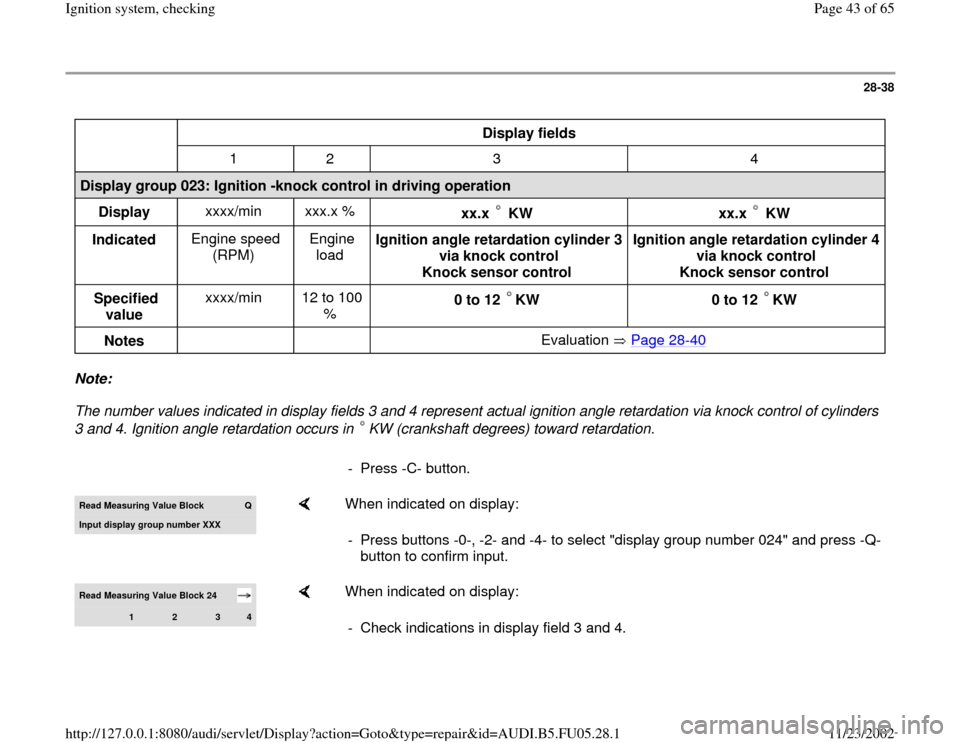
28-38
Display fields
1 2 3 4
Display group 023: Ignition -knock control in driving operation
Display xxxx/min xxx.x %
xx.x KW
xx.x KW
Indicated Engine speed
(RPM) Engine
load Ignition angle retardation cylinder 3
via knock control
Knock sensor control Ignition angle retardation cylinder 4
via knock control
Knock sensor control
Specified
value xxxx/min 12 to 100
% 0 to 12 KW
0 to 12 KW
Notes Evaluation Page 28
-40
Note:
The number values indicated in display fields 3 and 4 represent actual ignition angle retardation via knock control of cylinders
3 and 4. Ignition angle retardation occurs in KW (crankshaft degrees) toward retardation.
- Press -C- button.Read Measurin
g Value Block
Q
Input displa
y group number XXX
When indicated on display:
- Press buttons -0-, -2- and -4- to select "display group number 024" and press -Q-
button to confirm input.
Read Measuring Value Block 24
1
2
3
4
When indicated on display:
- Check indications in display field 3 and 4.
Pa
ge 43 of 65 I
gnition s
ystem, checkin
g
11/23/2002 htt
p://127.0.0.1:8080/audi/servlet/Dis
play?action=Goto&t
yp
e=re
pair&id=AUDI.B5.FU05.28.1
Page 51 of 65
28-46
Component location Overview of Component
Locations, page Page 24
-5
Notes:
Camshaft Position (CMP) Sensor -G40- is
located at rear of left cylinder block (bank 2).
Camshaft Position (CMP) Sensor 2 -G163- is
located at front of right cylinder block (bank 1).
Checking activation
- Slide back rubber grommet at connector of the
respective Camshaft Position (CMP) Sensor
(connector remains connected to Camshaft
Position (CMP) Sensor).
Note:
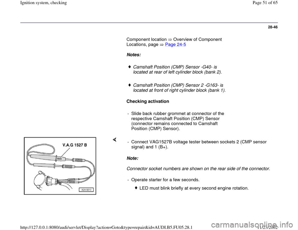
Connector socket numbers are shown on the rear side of the connector. - Connect VAG1527B voltage tester between sockets 2 (CMP sensor
signal) and 1 (B+).
- Operate starter for a few seconds.
LED must blink briefly at every second engine rotation.
Pa
ge 51 of 65 I
gnition s
ystem, checkin
g
11/23/2002 htt
p://127.0.0.1:8080/audi/servlet/Dis
play?action=Goto&t
yp
e=re
pair&id=AUDI.B5.FU05.28.1
Page 56 of 65
28-50
- Repair open circuit or short circuit if
necessary.
- If, after erasing DTC memory for the sake of the
test, a DTC relating to the Camshaft Position
(CMP) sensor (hall sensor) is indicated again,
even though all previous tests were OK, the
following malfunction is possible:
Shutter wheel for Camshaft Position (CMP)
sensor is not aligned properly.
Check phase position of Camshaft Position
(CMP) sensor
- Connect VAS5051 tester or VAG1551 scan tool
and select the control module for engine
electronics using "address word" 01 Page 01
-
9 .
Engine must run at idle for this.Rapid data transfer
HELP
Select function XX
When indicated on display:
- Press buttons -0- and -8- to select "Read Measuring Value Block" and
press -Q- button to confirm input.
Read Measurin
g Value Block
Q
Input display group number XXX
When indicated on display:
Pa
ge 56 of 65 I
gnition s
ystem, checkin
g
11/23/2002 htt
p://127.0.0.1:8080/audi/servlet/Dis
play?action=Goto&t
yp
e=re
pair&id=AUDI.B5.FU05.28.1