battery AUDI A8 1998 D2 / 1.G ATQ Engine Motronic Injection System Servicing Workshop Manual
[x] Cancel search | Manufacturer: AUDI, Model Year: 1998, Model line: A8, Model: AUDI A8 1998 D2 / 1.GPages: 78, PDF Size: 1 MB
Page 3 of 78
24-2
It is possible that the control module will
recognize a malfunction and store a DTC during
some tests. After completing all tests and
repairs, DTC memory should therefore be
checked and erased if necessary. Readiness
code must be generated after DTC memory is
erased Page 01
-82
.
Always switch ignition off before cleaning
engine.
The battery should only be disconnected and
reconnected when the ignition is turned off,
since otherwise the Engine Control Module
(ECM) can be damaged.
WARNING!
Fuel system is under pressure! Place a cloth
around the connection point before opening
system. Then release pressure by carefully
loosening connection point.
Pa
ge 3 of 78 Motronic in
jection s
ystem, servicin
g
11/23/2002 htt
p://127.0.0.1:8080/audi/servlet/Dis
play?action=Goto&t
yp
e=re
pair&id=AUDI.B5.FU05.24.1
Page 35 of 78
24-30
Fuel pressure regulator and residual
pressure, checking
Note:
Fuel pressure regulator regulates fuel pressure
according to intake manifold pressure. This
ensures that the pressure drop at the fuel
injectors remains the same for each speed and
load range of the engine.
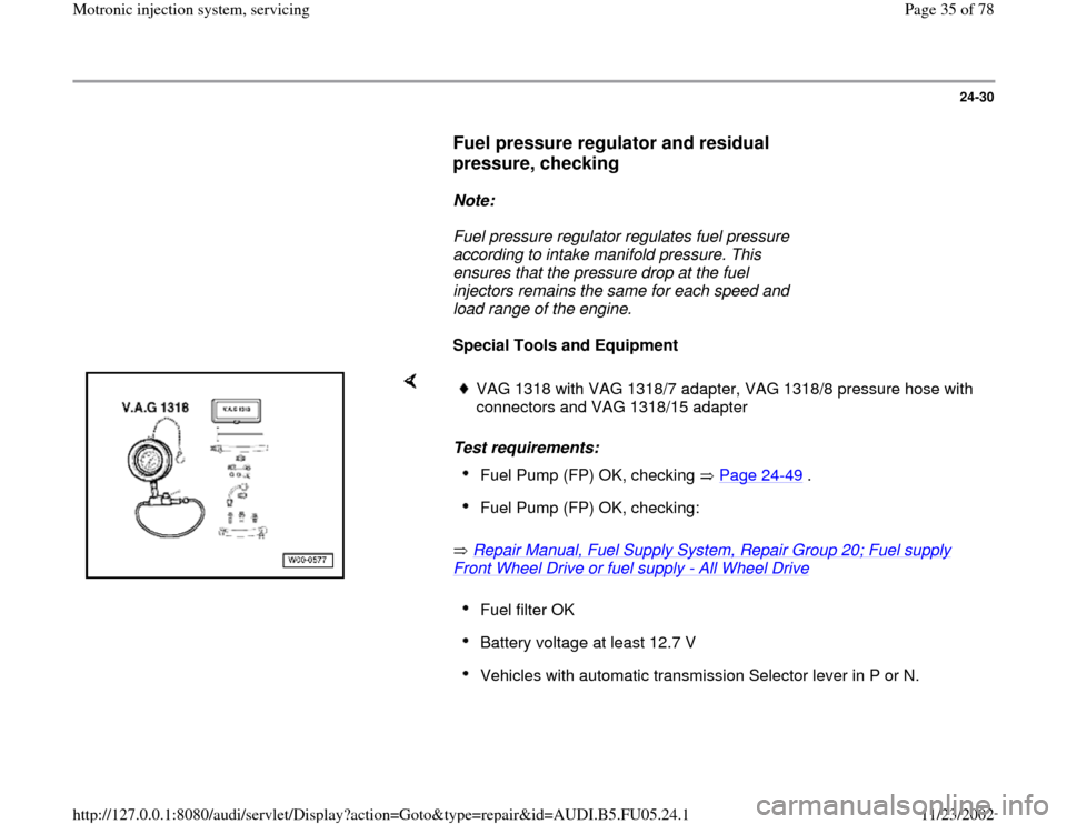
Special Tools and Equipment
Test requirements:
Repair Manual, Fuel Supply System, Repair Group 20; Fuel supply Front Wheel Drive or fuel supply
- All Wheel Drive
VAG 1318 with VAG 1318/7 adapter, VAG 1318/8 pressure hose with
connectors and VAG 1318/15 adapter Fuel Pump (FP) OK, checking Page 24
-49
.
Fuel Pump (FP) OK, checking: Fuel filter OK Battery voltage at least 12.7 V Vehicles with automatic transmission Selector lever in P or N.
Pa
ge 35 of 78 Motronic in
jection s
ystem, servicin
g
11/23/2002 htt
p://127.0.0.1:8080/audi/servlet/Dis
play?action=Goto&t
yp
e=re
pair&id=AUDI.B5.FU05.24.1
Page 60 of 78
24-50
Voltage is supplied to the Fuel Pump (FP) and
several components of the injection system via
the Fuel Pump (FP) relay -J17-.
Engine must be turning for Fuel Pump (FP) relay
-J17- to close. This means that the relay does
not receive Ground (GND) (via ECM) until the
ECM recognizes RPM signals.
Note:
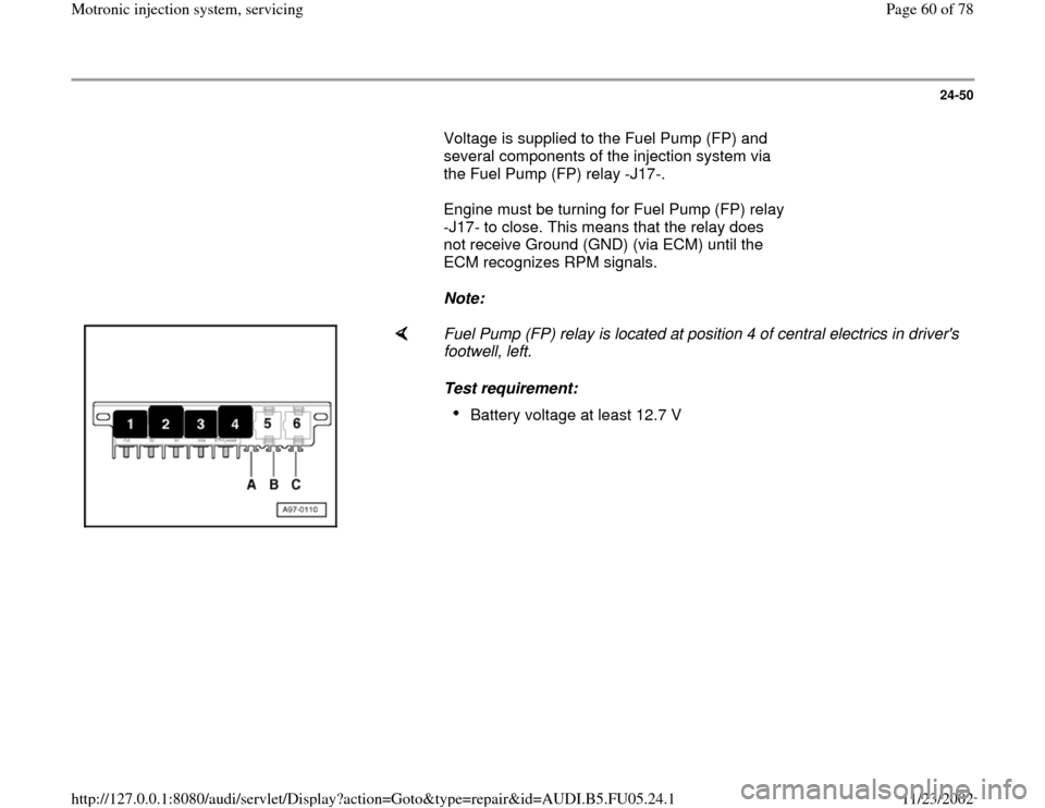
Fuel Pump (FP) relay is located at position 4 of central electrics in driver's
footwell, left.
Test requirement:
Battery voltage at least 12.7 V
Pa
ge 60 of 78 Motronic in
jection s
ystem, servicin
g
11/23/2002 htt
p://127.0.0.1:8080/audi/servlet/Dis
play?action=Goto&t
yp
e=re
pair&id=AUDI.B5.FU05.24.1
Page 62 of 78
24-52
B - If relay triggers, but Fuel Pump (FP) does not
run:
- Check voltage supply for Fuel Pump (FP) and
components (via Fuel Pump -FP- relay) Page
24
-54
.
Check voltage supply of Fuel Pump (FP)
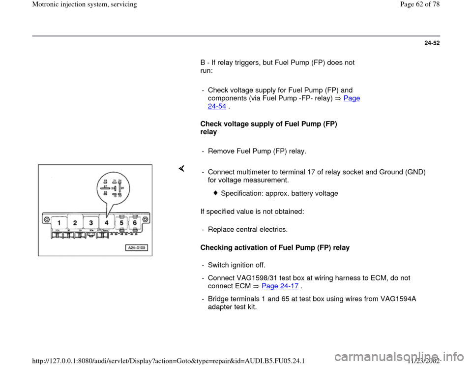
relay
- Remove Fuel Pump (FP) relay.
If specified value is not obtained:
Checking activation of Fuel Pump (FP) relay - Connect multimeter to terminal 17 of relay socket and Ground (GND)
for voltage measurement.
Specification: approx. battery voltage
- Replace central electrics.
- Switch ignition off.
- Connect VAG1598/31 test box at wiring harness to ECM, do not
connect ECM Page 24
-17
.
- Bridge terminals 1 and 65 at test box using wires from VAG1594A
adapter test kit.
Pa
ge 62 of 78 Motronic in
jection s
ystem, servicin
g
11/23/2002 htt
p://127.0.0.1:8080/audi/servlet/Dis
play?action=Goto&t
yp
e=re
pair&id=AUDI.B5.FU05.24.1
Page 63 of 78
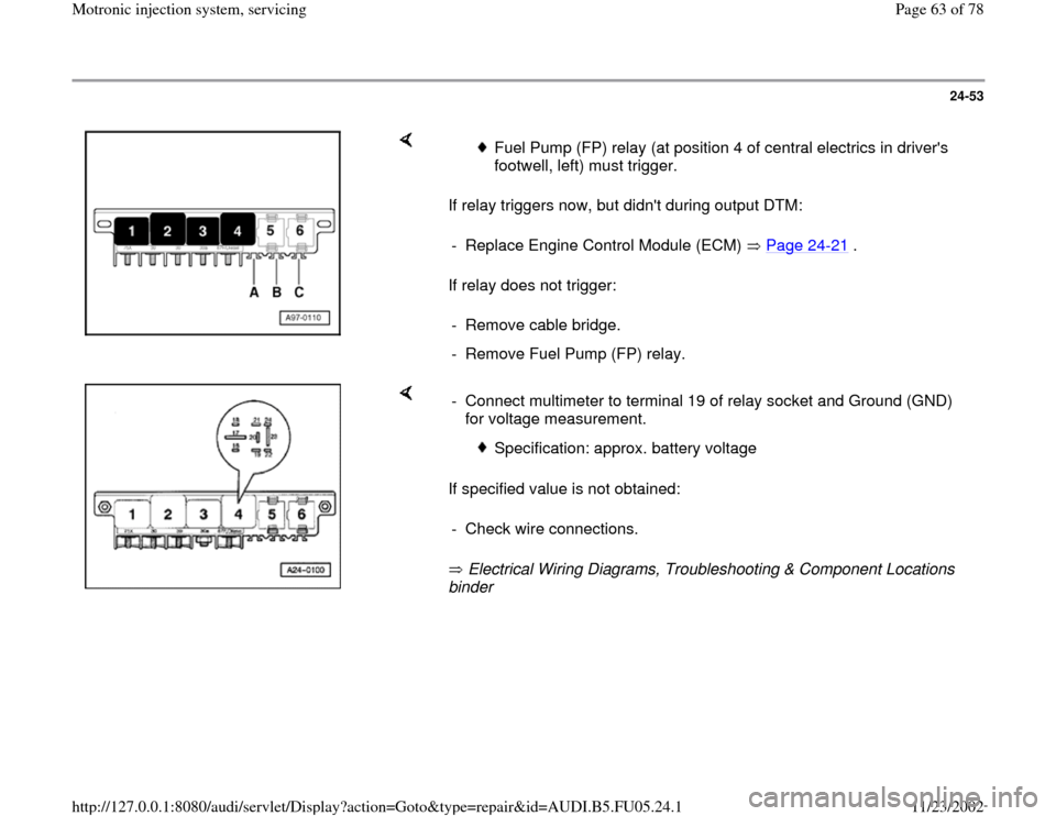
24-53
If relay triggers now, but didn't during output DTM:
If relay does not trigger:
Fuel Pump (FP) relay (at position 4 of central electrics in driver's
footwell, left) must trigger.
- Replace Engine Control Module (ECM) Page 24
-21
.
- Remove cable bridge.
- Remove Fuel Pump (FP) relay.
If specified value is not obtained:
Electrical Wiring Diagrams, Troubleshooting & Component Locations
binder - Connect multimeter to terminal 19 of relay socket and Ground (GND)
for voltage measurement.
Specification: approx. battery voltage
- Check wire connections.
Pa
ge 63 of 78 Motronic in
jection s
ystem, servicin
g
11/23/2002 htt
p://127.0.0.1:8080/audi/servlet/Dis
play?action=Goto&t
yp
e=re
pair&id=AUDI.B5.FU05.24.1
Page 65 of 78
24-55
- Connect multimeter for voltage measurement to
Ground (GND) and to one terminal of the
following fuses in the fuse holder.
Fuse
Specified value at one of the
terminals
S228 approx. battery voltage
S229 approx. battery voltage
S234 approx. battery voltage
If specified values are not obtained:
- Repeat test at another terminal of fuse socket.
If specified values are not obtained again:
- Check wire connections.
Electrical Wiring Diagrams, Troubleshooting &
Component Locations binder If no malfunctions are detected:
- Replace Fuel Pump (FP) relay -J17-.
- Re-insert the fuses.
Pa
ge 65 of 78 Motronic in
jection s
ystem, servicin
g
11/23/2002 htt
p://127.0.0.1:8080/audi/servlet/Dis
play?action=Goto&t
yp
e=re
pair&id=AUDI.B5.FU05.24.1
Page 73 of 78
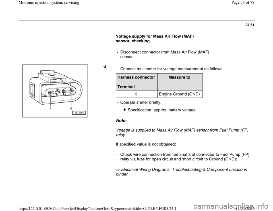
24-61
Voltage supply for Mass Air Flow (MAF)
sensor, checking
- Disconnect connector from Mass Air Flow (MAF)
sensor.
Note:
Voltage is supplied to Mass Air Flow (MAF) sensor from Fuel Pump (FP)
relay.
If specified value is not obtained:
Electrical Wiring Diagrams, Troubleshooting & Component Locations
binder - Connect multimeter for voltage measurement as follows.Harness connector
Terminal
Measure to
3 Engine Ground (GND)
- Operate starter briefly.
Specification: approx. battery voltage
- Check wire connection from terminal 3 of connector to Fuel Pump (FP)
relay via fuse for open circuit and short circuit to Ground (GND):
Pa
ge 73 of 78 Motronic in
jection s
ystem, servicin
g
11/23/2002 htt
p://127.0.0.1:8080/audi/servlet/Dis
play?action=Goto&t
yp
e=re
pair&id=AUDI.B5.FU05.24.1
Page 74 of 78
24-62
- Repair open circuit or short circuit if
necessary.
Note:
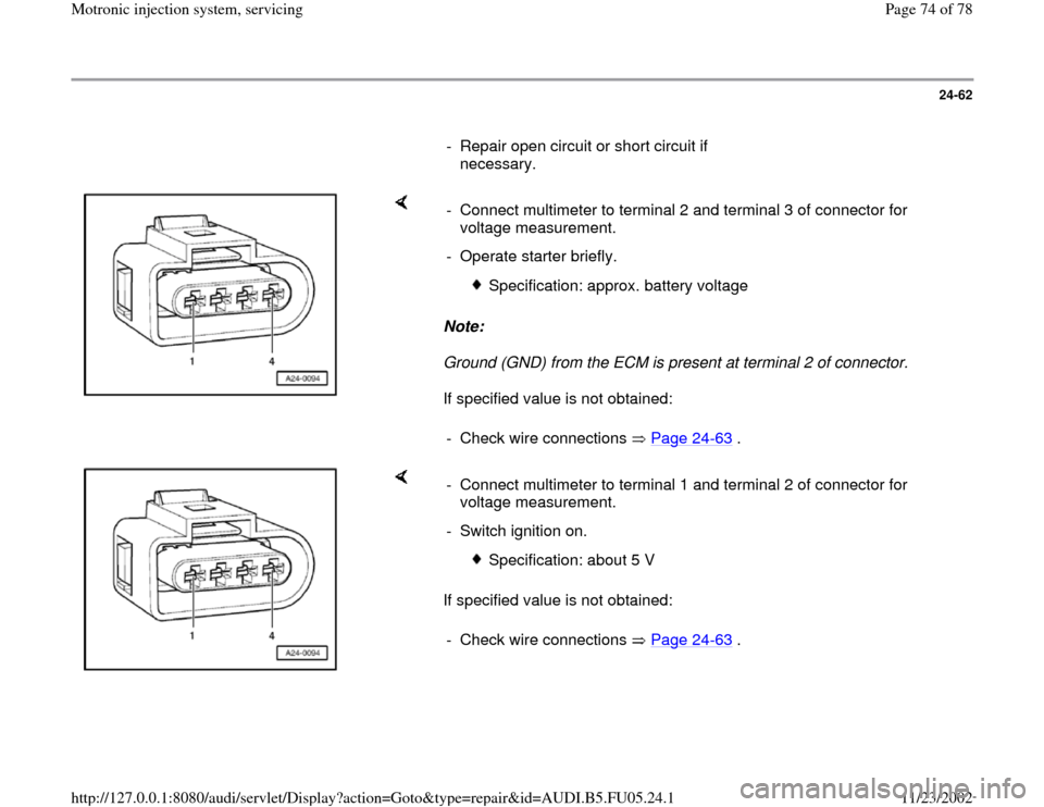
Ground (GND) from the ECM is present at terminal 2 of connector.
If specified value is not obtained: - Connect multimeter to terminal 2 and terminal 3 of connector for
voltage measurement.
- Operate starter briefly.
Specification: approx. battery voltage
- Check wire connections Page 24
-63
.
If specified value is not obtained: - Connect multimeter to terminal 1 and terminal 2 of connector for
voltage measurement.
- Switch ignition on.
Specification: about 5 V
- Check wire connections Page 24
-63
.
Pa
ge 74 of 78 Motronic in
jection s
ystem, servicin
g
11/23/2002 htt
p://127.0.0.1:8080/audi/servlet/Dis
play?action=Goto&t
yp
e=re
pair&id=AUDI.B5.FU05.24.1