fuel pump AUDI A8 1998 D2 / 1.G ATQ Engine Motronic Injection System Servicing Workshop Manual
[x] Cancel search | Manufacturer: AUDI, Model Year: 1998, Model line: A8, Model: AUDI A8 1998 D2 / 1.GPages: 78, PDF Size: 1 MB
Page 12 of 78
24-10
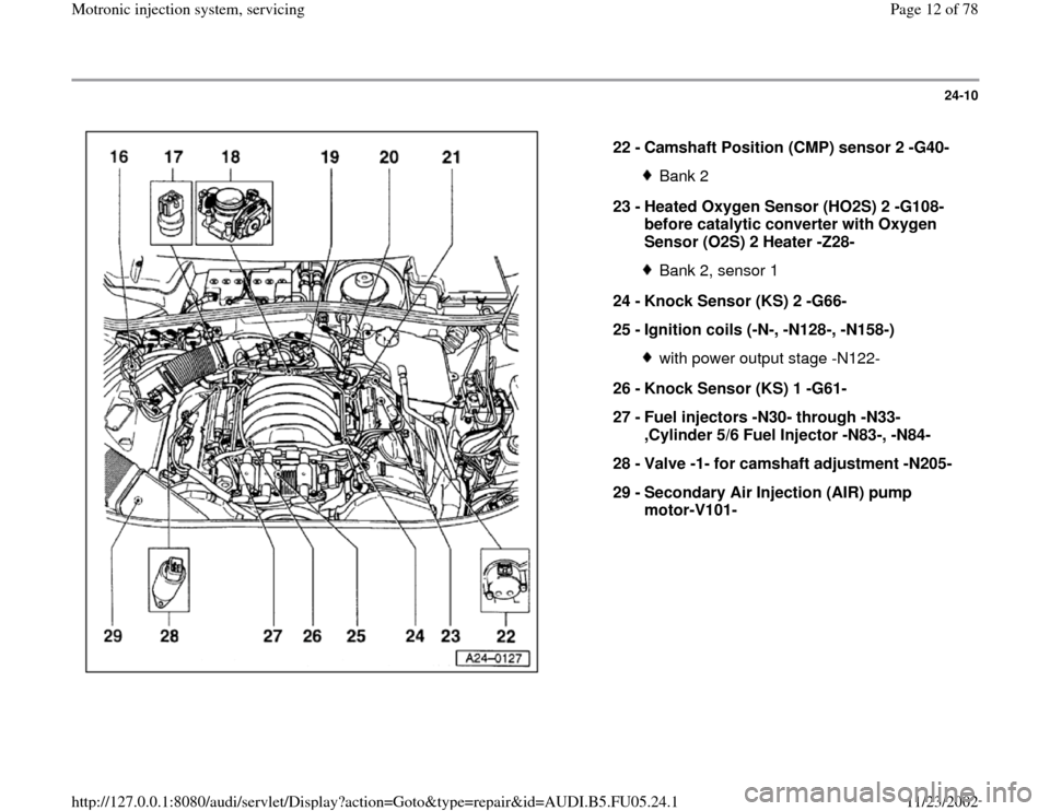
22 -
Camshaft Position (CMP) sensor 2 -G40-
Bank 2
23 -
Heated Oxygen Sensor (HO2S) 2 -G108-
before catalytic converter with Oxygen
Sensor (O2S) 2 Heater -Z28- Bank 2, sensor 1
24 -
Knock Sensor (KS) 2 -G66-
25 -
Ignition coils (-N-, -N128-, -N158-) with power output stage -N122-
26 -
Knock Sensor (KS) 1 -G61-
27 -
Fuel injectors -N30- through -N33-
,Cylinder 5/6 Fuel Injector -N83-, -N84-
28 -
Valve -1- for camshaft adjustment -N205-
29 -
Secondary Air Injection (AIR) pump
motor-V101-
Pa
ge 12 of 78 Motronic in
jection s
ystem, servicin
g
11/23/2002 htt
p://127.0.0.1:8080/audi/servlet/Dis
play?action=Goto&t
yp
e=re
pair&id=AUDI.B5.FU05.24.1
Page 14 of 78
24-12
Note:
In order to assure sufficiently secure fitting, switches must not be installed
more than once.
Adjusting switch:
Repair Manual, Brake System, ABS, ABS/EDL, Repair Group 46
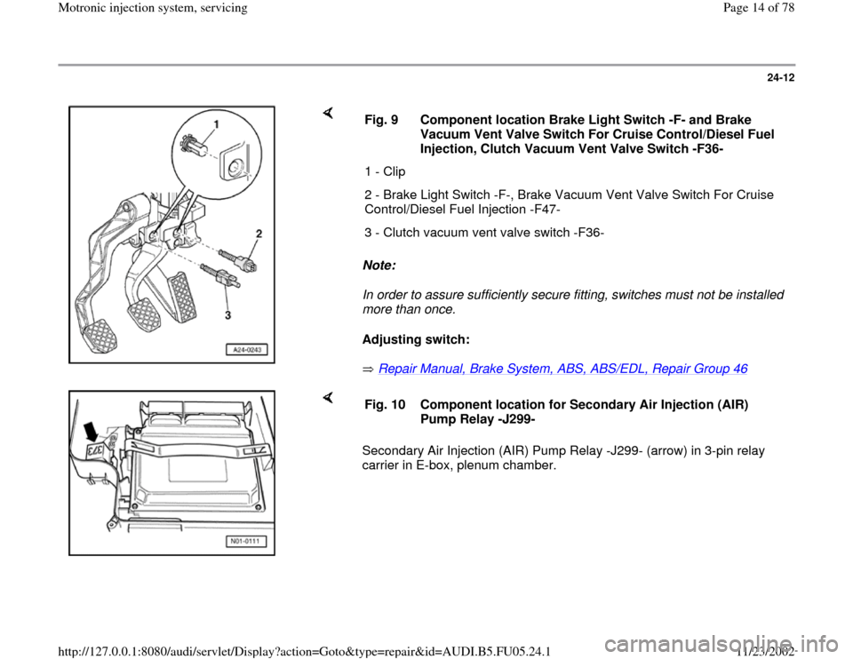
Fig. 9 Component location Brake Light Switch -F- and Brake
Vacuum Vent Valve Switch For Cruise Control/Diesel Fuel
Injection, Clutch Vacuum Vent Valve Switch -F36-
1 - Clip
2 - Brake Light Switch -F-, Brake Vacuum Vent Valve Switch For Cruise
Control/Diesel Fuel Injection -F47-
3 - Clutch vacuum vent valve switch -F36-
Secondary Air Injection (AIR) Pump Relay -J299- (arrow) in 3-pin relay
carrier in E-box, plenum chamber. Fig. 10 Component location for Secondary Air Injection (AIR)
Pump Relay -J299-
Pa
ge 14 of 78 Motronic in
jection s
ystem, servicin
g
11/23/2002 htt
p://127.0.0.1:8080/audi/servlet/Dis
play?action=Goto&t
yp
e=re
pair&id=AUDI.B5.FU05.24.1
Page 15 of 78
24-13
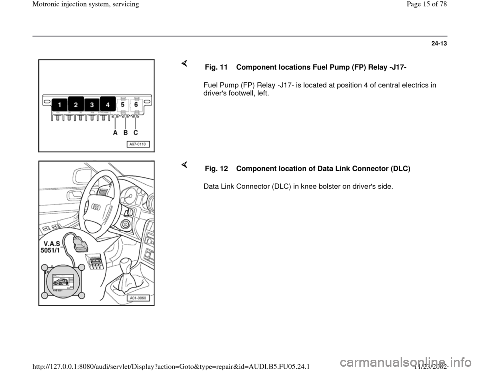
Fuel Pump (FP) Relay -J17- is located at position 4 of central electrics in
driver's footwell, left. Fig. 11 Component locations Fuel Pump (FP) Relay -J17-
Data Link Connector (DLC) in knee bolster on driver's side. Fig. 12 Component location of Data Link Connector (DLC)
Pa
ge 15 of 78 Motronic in
jection s
ystem, servicin
g
11/23/2002 htt
p://127.0.0.1:8080/audi/servlet/Dis
play?action=Goto&t
yp
e=re
pair&id=AUDI.B5.FU05.24.1
Page 35 of 78
24-30
Fuel pressure regulator and residual
pressure, checking
Note:
Fuel pressure regulator regulates fuel pressure
according to intake manifold pressure. This
ensures that the pressure drop at the fuel
injectors remains the same for each speed and
load range of the engine.
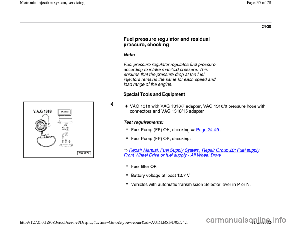
Special Tools and Equipment
Test requirements:
Repair Manual, Fuel Supply System, Repair Group 20; Fuel supply Front Wheel Drive or fuel supply
- All Wheel Drive
VAG 1318 with VAG 1318/7 adapter, VAG 1318/8 pressure hose with
connectors and VAG 1318/15 adapter Fuel Pump (FP) OK, checking Page 24
-49
.
Fuel Pump (FP) OK, checking: Fuel filter OK Battery voltage at least 12.7 V Vehicles with automatic transmission Selector lever in P or N.
Pa
ge 35 of 78 Motronic in
jection s
ystem, servicin
g
11/23/2002 htt
p://127.0.0.1:8080/audi/servlet/Dis
play?action=Goto&t
yp
e=re
pair&id=AUDI.B5.FU05.24.1
Page 37 of 78
24-32
- Measure fuel pressure.
Specification: 3.8 to 4.2 bar
- If the specified value is not reached, replace
pressure regulator on a trial basis and repeat
pressure test.
- If the specified value is not reached again, check
Fuel Pump (FP) or supply line for damage (e.g.
pinched areas) and replace if necessary.
- If the specified value is exceeded, check return
line for damage (e.g. pinched areas) and replace
if necessary.
Note:
During the following test, the engine must not run
for an unnecessarily long period of time with the
vacuum hose removed. Otherwise, the higher
fuel pressure can cause enrichment of the fuel to
air ratio, which under some circumstances can
cause the oxygen sensor control limits to be
exceeded, causing a DTC to be stored.
- Start engine and let run at idle.
-
Switch of electrical consumers (A/C system
Pa
ge 37 of 78 Motronic in
jection s
ystem, servicin
g
11/23/2002 htt
p://127.0.0.1:8080/audi/servlet/Dis
play?action=Goto&t
yp
e=re
pair&id=AUDI.B5.FU05.24.1
Page 41 of 78
24-34
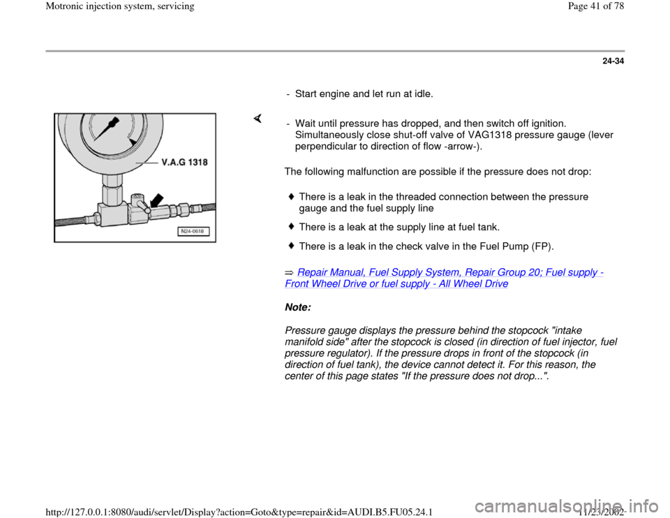
- Start engine and let run at idle.
The following malfunction are possible if the pressure does not drop:
Repair Manual, Fuel Supply System, Repair Group 20; Fuel supply
-
Front Wheel Drive or fuel supply
- All Wheel Drive
Note:
Pressure gauge displays the pressure behind the stopcock "intake
manifold side" after the stopcock is closed (in direction of fuel injector, fuel
pressure regulator). If the pressure drops in front of the stopcock (in
direction of fuel tank), the device cannot detect it. For this reason, the
center of this page states "If the pressure does not drop...". - Wait until pressure has dropped, and then switch off ignition.
Simultaneously close shut-off valve of VAG1318 pressure gauge (lever
perpendicular to direction of flow -arrow-).
There is a leak in the threaded connection between the pressure
gauge and the fuel supply line There is a leak at the supply line at fuel tank.There is a leak in the check valve in the Fuel Pump (FP).
Pa
ge 41 of 78 Motronic in
jection s
ystem, servicin
g
11/23/2002 htt
p://127.0.0.1:8080/audi/servlet/Dis
play?action=Goto&t
yp
e=re
pair&id=AUDI.B5.FU05.24.1
Page 45 of 78
24-38
Checking voltage supply
Test requirements:
Fuel Pump (FP) OK, checking Page 24
-
49
.
Fuse for fuel injectors OK
Electrical Wiring Diagrams, Troubleshooting &
Component Locations binder
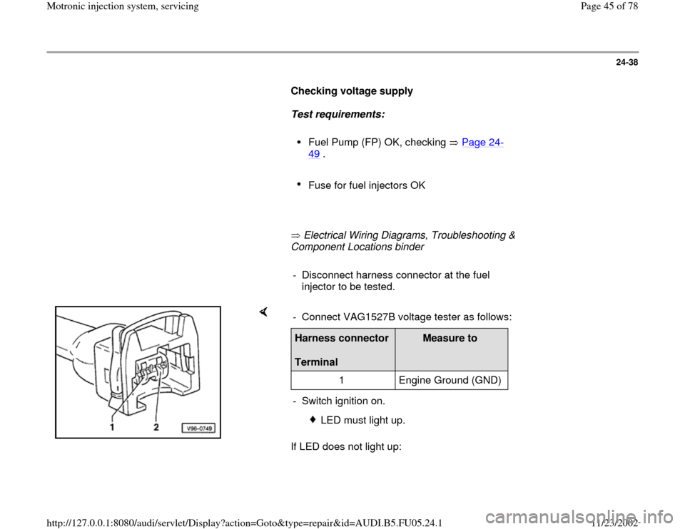
- Disconnect harness connector at the fuel
injector to be tested.
If LED does not light up: - Connect VAG1527B voltage tester as follows:Harness connector
Terminal
Measure to
1 Engine Ground (GND)
- Switch ignition on.
LED must light up.
Pa
ge 45 of 78 Motronic in
jection s
ystem, servicin
g
11/23/2002 htt
p://127.0.0.1:8080/audi/servlet/Dis
play?action=Goto&t
yp
e=re
pair&id=AUDI.B5.FU05.24.1
Page 55 of 78
24-46
Test requirement:
Fuel pressure OK, checking Page 24
-30
.
Test sequence
- Remove fuel distributor including fuel injectors
from intake manifold Page 24
-43
. Fuel lines
remain connected.
- Connect VAG1598/31 test box at wiring harness
to ECM, do not connect ECM Page 24
-17
.
- Bridge terminals 1 and 65 at test box using
adapter cables from VAG1594A connector test
kit (this step supplies Ground -GND- to one side
of relay coil for Fuel Pump -FP- relay).
Note:
Fuel Pump (FP) relay is supplied with B+ via the
central electric (terminal 30). Fuel Pump (FP)
relay receives minus via the cable bridge in test
box. The Fuel Pump (FP) is now running
constantly.
Pa
ge 55 of 78 Motronic in
jection s
ystem, servicin
g
11/23/2002 htt
p://127.0.0.1:8080/audi/servlet/Dis
play?action=Goto&t
yp
e=re
pair&id=AUDI.B5.FU05.24.1
Page 56 of 78
24-47
Checking Proper Seal
- Check proper seal of fuel injectors (visual
inspection). With Fuel Pump (FP) running, only 1
to 2 drops per minute may drip out per injector.
- If fuel loss is greater, stop Fuel Pump (FP) from
running (disconnect cable bridge) and replace
faulty fuel injector Page 24
-43
.
Checking Injection Quantity
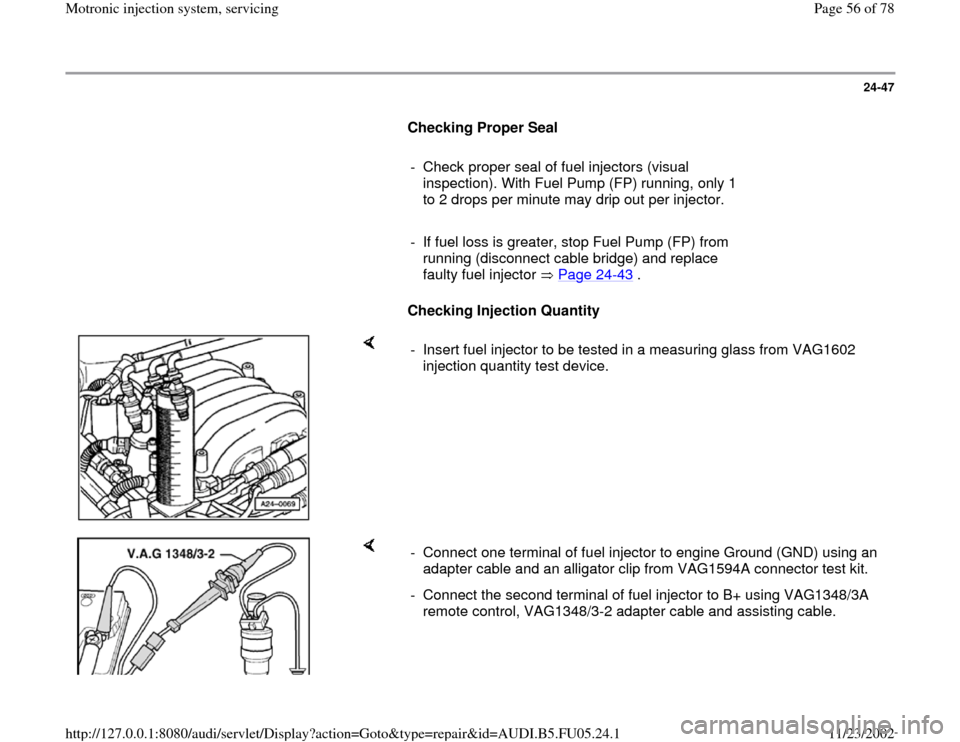
- Insert fuel injector to be tested in a measuring glass from VAG1602
injection quantity test device.
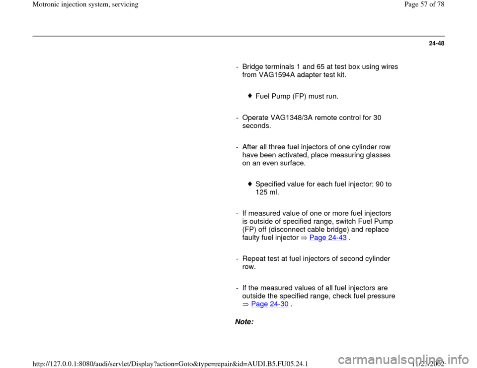
- Connect one terminal of fuel injector to engine Ground (GND) using an
adapter cable and an alligator clip from VAG1594A connector test kit.
- Connect the second terminal of fuel injector to B+ using VAG1348/3A
remote control, VAG1348/3-2 adapter cable and assisting cable.
Pa
ge 56 of 78 Motronic in
jection s
ystem, servicin
g
11/23/2002 htt
p://127.0.0.1:8080/audi/servlet/Dis
play?action=Goto&t
yp
e=re
pair&id=AUDI.B5.FU05.24.1
Page 57 of 78
24-48
- Bridge terminals 1 and 65 at test box using wires
from VAG1594A adapter test kit.
Fuel Pump (FP) must run.
- Operate VAG1348/3A remote control for 30
seconds.
- After all three fuel injectors of one cylinder row
have been activated, place measuring glasses
on an even surface.
Specified value for each fuel injector: 90 to
125 ml.
- If measured value of one or more fuel injectors
is outside of specified range, switch Fuel Pump
(FP) off (disconnect cable bridge) and replace
faulty fuel injector Page 24
-43
.
- Repeat test at fuel injectors of second cylinder
row.
- If the measured values of all fuel injectors are
outside the specified range, check fuel pressure
Page 24
-30
.
Note:
Pa
ge 57 of 78 Motronic in
jection s
ystem, servicin
g
11/23/2002 htt
p://127.0.0.1:8080/audi/servlet/Dis
play?action=Goto&t
yp
e=re
pair&id=AUDI.B5.FU05.24.1