lock AUDI A8 1999 D2 / 1.G 01V Transmission Select Lever Mechanism User Guide
[x] Cancel search | Manufacturer: AUDI, Model Year: 1999, Model line: A8, Model: AUDI A8 1999 D2 / 1.GPages: 75, PDF Size: 0.76 MB
Page 19 of 75
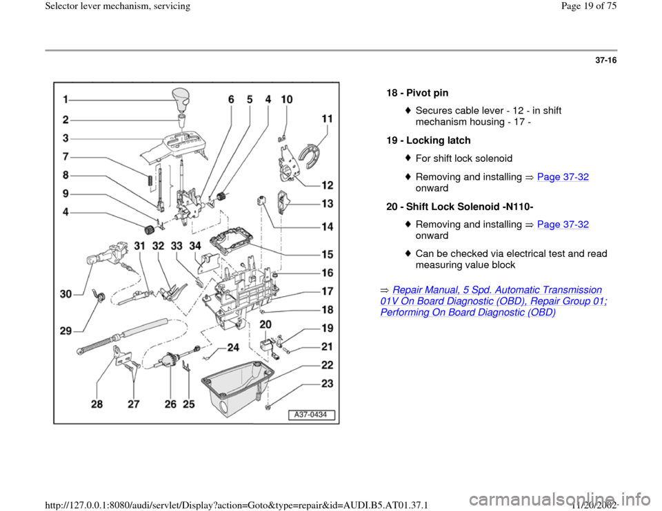
37-16
Repair Manual, 5 Spd. Automatic Transmission
01V On Board Diagnostic (OBD), Repair Group 01; Performing On Board Diagnostic (OBD)
18 -
Pivot pin
Secures cable lever - 12 - in shift
mechanism housing - 17 -
19 -
Locking latch For shift lock solenoidRemoving and installing Page 37
-32
onward
20 -
Shift Lock Solenoid -N110-
Removing and installing Page 37
-32
onward
Can be checked via electrical test and read
measuring value block
Pa
ge 19 of 75 Selector lever mechanism, servicin
g
11/20/2002 htt
p://127.0.0.1:8080/audi/servlet/Dis
play?action=Goto&t
yp
e=re
pair&id=AUDI.B5.AT01.37.1
Page 20 of 75
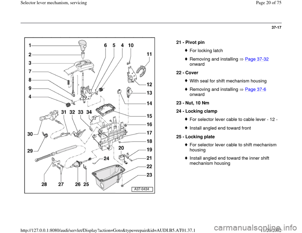
37-17
21 -
Pivot pin
For locking latchRemoving and installing Page 37
-32
onward
22 -
Cover
With seal for shift mechanism housingRemoving and installing Page 37
-6
onward
23 -
Nut, 10 Nm
24 -
Locking clamp
For selector lever cable to cable lever - 12 -Install angled end toward front
25 -
Locking plate For selector lever cable to shift mechanism
housing Install angled end toward the inner shift
mechanism housing
Pa
ge 20 of 75 Selector lever mechanism, servicin
g
11/20/2002 htt
p://127.0.0.1:8080/audi/servlet/Dis
play?action=Goto&t
yp
e=re
pair&id=AUDI.B5.AT01.37.1
Page 22 of 75
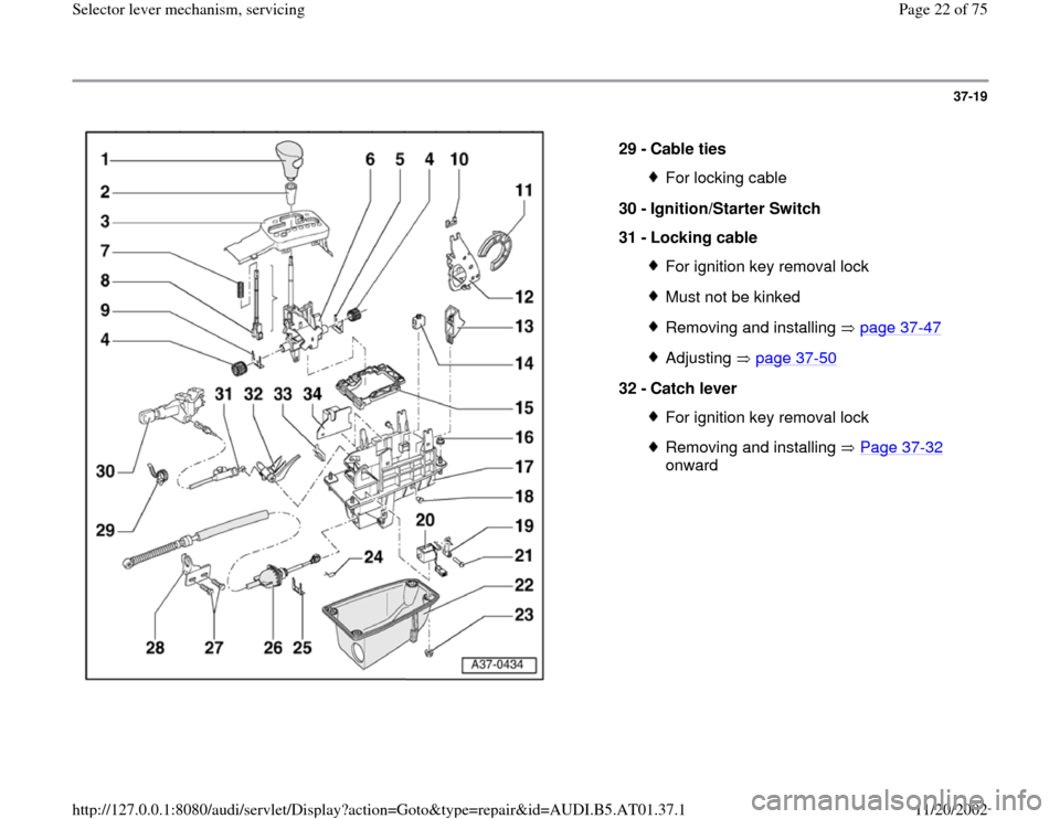
37-19
29 -
Cable ties
For locking cable
30 -
Ignition/Starter Switch
31 -
Locking cable For ignition key removal lockMust not be kinkedRemoving and installing page 37
-47
Adjusting page 37
-50
32 -
Catch lever
For ignition key removal lockRemoving and installing Page 37
-32
onward
Pa
ge 22 of 75 Selector lever mechanism, servicin
g
11/20/2002 htt
p://127.0.0.1:8080/audi/servlet/Dis
play?action=Goto&t
yp
e=re
pair&id=AUDI.B5.AT01.37.1
Page 23 of 75
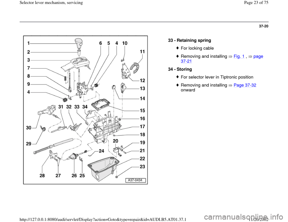
37-20
33 -
Retaining spring
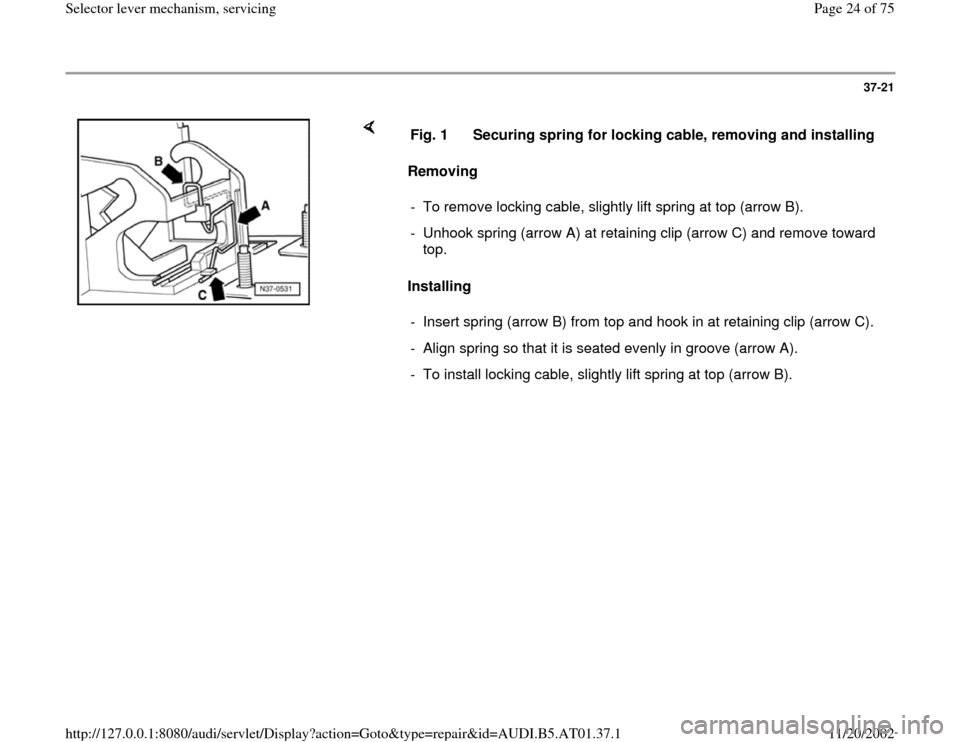
For locking cableRemoving and installing Fig. 1
, page
37
-21
34 -
Storing
For selector lever in Tiptronic positionRemoving and installing Page 37
-32
onward
Pa
ge 23 of 75 Selector lever mechanism, servicin
g
11/20/2002 htt
p://127.0.0.1:8080/audi/servlet/Dis
play?action=Goto&t
yp
e=re
pair&id=AUDI.B5.AT01.37.1
Page 24 of 75
37-21
Removing
Installing Fig. 1 Securing spring for locking cable, removing and installing
- To remove locking cable, slightly lift spring at top (arrow B).
- Unhook spring (arrow A) at retaining clip (arrow C) and remove toward
top.
- Insert spring (arrow B) from top and hook in at retaining clip (arrow C).
- Align spring so that it is seated evenly in groove (arrow A).
- To install locking cable, slightly lift spring at top (arrow B).
Pa
ge 24 of 75 Selector lever mechanism, servicin
g
11/20/2002 htt
p://127.0.0.1:8080/audi/servlet/Dis
play?action=Goto&t
yp
e=re
pair&id=AUDI.B5.AT01.37.1
Page 33 of 75
37-30
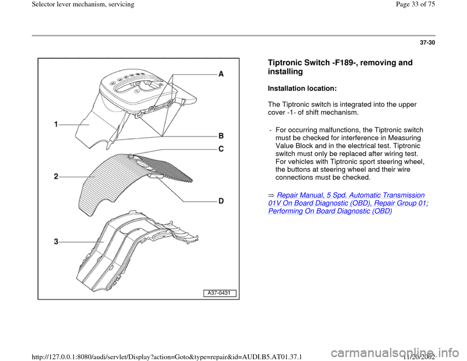
Tiptronic Switch -F189-, removing and
installing
Installation location:
The Tiptronic switch is integrated into the upper
cover -1- of shift mechanism.
Repair Manual, 5 Spd. Automatic Transmission
01V On Board Diagnostic (OBD), Repair Group 01; Performing On Board Diagnostic (OBD)
- For occurring malfunctions, the Tiptronic switch
must be checked for interference in Measuring
Value Block and in the electrical test. Tiptronic
switch must only be replaced after wiring test.
For vehicles with Tiptronic sport steering wheel,
the buttons at steering wheel and their wire
connections must be checked. Pa
ge 33 of 75 Selector lever mechanism, servicin
g
11/20/2002 htt
p://127.0.0.1:8080/audi/servlet/Dis
play?action=Goto&t
yp
e=re
pair&id=AUDI.B5.AT01.37.1
Page 35 of 75
37-32
Tiptronic shift mechanism,
disassembling and assembling
(sequence)
Disassembly of suspension strut
- Remove shift mechanism page 37
-6 .
- First remove stop buffers from cable lever
- Shift selector lever into Tiptronic position and
then remove frame.
- Shift selector lever into position "2".
- Disengage lever for locking cable by lifting it out
of its bearing and remove from shift mechanism
housing.
- Shift selector lever into position "D".
- Catch spring for Tiptronic position is carefully
pried out of the shift mechanism housing from
the outside.
- Pull out retainer for selector lever bushings.
Pa
ge 35 of 75 Selector lever mechanism, servicin
g
11/20/2002 htt
p://127.0.0.1:8080/audi/servlet/Dis
play?action=Goto&t
yp
e=re
pair&id=AUDI.B5.AT01.37.1
Page 37 of 75
37-33
- Remove complete selector lever.
- Disassemble selector lever page 37
-36
.
- To remove bearing for Tiptronic position of
selector lever, unlatch retaining tabs at shift
mechanism housing and remove bearing inward.
- Press out pin for locking latch using a drift.
- Remove shift lock solenoid together with locking
latch upward.
- Catch spring for selector lever positions is
carefully pried out of the shift mechanism
housing from the outside.
- Pry out both pins of the cable lever/catch.
- Pull cable lever/catch with opening of the catch
out of the shift mechanism housing upward.
- Unclip catch from the cable lever.
Pa
ge 37 of 75 Selector lever mechanism, servicin
g
11/20/2002 htt
p://127.0.0.1:8080/audi/servlet/Dis
play?action=Goto&t
yp
e=re
pair&id=AUDI.B5.AT01.37.1
Page 38 of 75
37-34
Assembly of suspension strut
- Clip catch into cable lever.
- Slide cable lever/catch into the shift mechanism
housing with opening of the catch forward.
- Drive both pins of the cable lever/catch into the
shift mechanism housing from both sides up to
stop.
- Press catch spring with roller for selector lever
position into its mount in shift mechanism
housing up to stop.
- Shift lock solenoid together with locking latch
must be slid into the shift mechanism housing
from the top.
- Carefully drive in pin for locking latch.
- Using a screwdriver, mechanically check for
engagement of the locking latch in position "P"
and "N" of selector lever.
- Insert complete selector lever into shift
mechanism housing.
Pa
ge 38 of 75 Selector lever mechanism, servicin
g
11/20/2002 htt
p://127.0.0.1:8080/audi/servlet/Dis
play?action=Goto&t
yp
e=re
pair&id=AUDI.B5.AT01.37.1
Page 40 of 75
37-35
- Slide both selector lever bushings into the shift
mechanism housing at front or rear.
- Install bearing bushing into shift mechanism
housing so that the angled ends point inward.
- Press catch spring for Tiptronic position into its
mount in shift mechanism housing up to stop.
- Shift selector lever into position "2".
- Lay cable lever into shift mechanism housing
and engage it noticeably in both bearing areas.
- Check locking function of locking lever. In
selector lever position "P", it must engage in the
catch and lock the shift mechanism.
- Set frame onto shift mechanism housing (ribbing
points upward) and insert buffer stop into cable
lever.
- Install shift mechanism page 37
-6 .
Pa
ge 40 of 75 Selector lever mechanism, servicin
g
11/20/2002 htt
p://127.0.0.1:8080/audi/servlet/Dis
play?action=Goto&t
yp
e=re
pair&id=AUDI.B5.AT01.37.1