engine AUDI A8 1999 D2 / 1.G AEB Engine Motronic MFI And Ignition System
[x] Cancel search | Manufacturer: AUDI, Model Year: 1999, Model line: A8, Model: AUDI A8 1999 D2 / 1.GPages: 135, PDF Size: 0.71 MB
Page 2 of 135
24-2
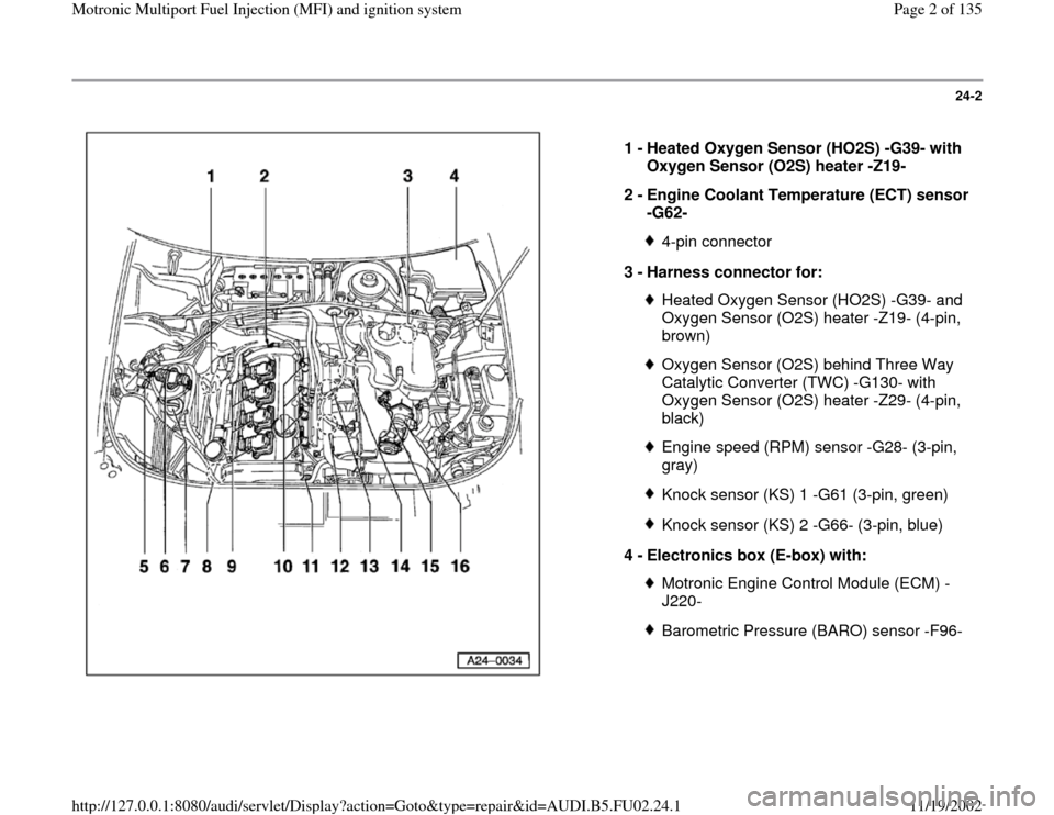
1 -
Heated Oxygen Sensor (HO2S) -G39- with
Oxygen Sensor (O2S) heater -Z19-
2 -
Engine Coolant Temperature (ECT) sensor
-G62-
4-pin connector
3 -
Harness connector for: Heated Oxygen Sensor (HO2S) -G39- and
Oxygen Sensor (O2S) heater -Z19- (4-pin,
brown) Oxygen Sensor (O2S) behind Three Way
Catalytic Converter (TWC) -G130- with
Oxygen Sensor (O2S) heater -Z29- (4-pin,
black) Engine speed (RPM) sensor -G28- (3-pin,
gray) Knock sensor (KS) 1 -G61 (3-pin, green)Knock sensor (KS) 2 -G66- (3-pin, blue)
4 -
Electronics box (E-box) with: Motronic Engine Control Module (ECM) -
J220- Barometric Pressure (BARO) sensor -F96-
Pa
ge 2 of 135 Motronic Multi
port Fuel In
jection
(MFI
) and i
gnition s
ystem
11/19/2002 htt
p://127.0.0.1:8080/audi/servlet/Dis
play?action=Goto&t
yp
e=re
pair&id=AUDI.B5.FU02.24.1
Page 4 of 135
24-4
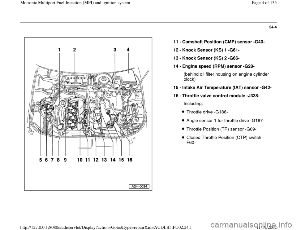
11 -
Camshaft Position (CMP) sensor -G40-
12 -
Knock Sensor (KS) 1 -G61-
13 -
Knock Sensor (KS) 2 -G66-
14 -
Engine speed (RPM) sensor -G28-
(behind oil filter housing on engine cylinder
block)
15 -
Intake Air Temperature (IAT) sensor -G42-
16 -
Throttle valve control module -J338-
Including:
Throttle drive -G186-Angle sensor 1 for throttle drive -G187-Throttle Position (TP) sensor -G69-Closed Throttle Position (CTP) switch -
F60-
Pa
ge 4 of 135 Motronic Multi
port Fuel In
jection
(MFI
) and i
gnition s
ystem
11/19/2002 htt
p://127.0.0.1:8080/audi/servlet/Dis
play?action=Goto&t
yp
e=re
pair&id=AUDI.B5.FU02.24.1
Page 5 of 135
24-5
Safety precautions
WARNING!
Fire hazard! Do not smoke, work near heaters
or open flame, or have anything nearby that
could ignite fuel. The fuel system is under
pressure. Before opening, cover connections
with a rag, and open carefully to release
pressure. Be alert when working on or near
the engine and ignition wires. High secondary
ignition voltage can cause serious personal
injury and damage vehicle components.
DO NOT touch or disconnect ignition system
wires when the engine is running or being
cranked at starting RPM.
DO NOT operate starter if fuel injectors are
removed.
Be sure the ignition is switched OFF, when:
Disconnecting or connecting the battery,
ignition wires, or test equipment leads
Disconnecting fuel injection system wiring
Washing the engine or engine
compartment.
Pa
ge 5 of 135 Motronic Multi
port Fuel In
jection
(MFI
) and i
gnition s
ystem
11/19/2002 htt
p://127.0.0.1:8080/audi/servlet/Dis
play?action=Goto&t
yp
e=re
pair&id=AUDI.B5.FU02.24.1
Page 6 of 135
BEFORE cranking engine at starting RPM
(e.g. for compression testing) disable ignition
and fuel injection systems:
Disconnect both ignition coil power output
stages, and both Motronic fuses at the E-box
in the plenum.
Disconnect harness connectors from all fuel
injectors.
Afterward, erase DTC memory.
Pa
ge 6 of 135 Motronic Multi
port Fuel In
jection
(MFI
) and i
gnition s
ystem
11/19/2002 htt
p://127.0.0.1:8080/audi/servlet/Dis
play?action=Goto&t
yp
e=re
pair&id=AUDI.B5.FU02.24.1
Page 7 of 135
24-6
CAUTION!
BEFORE disconnecting the battery:
Stop the engine.
Be sure the ignition is switched OFF (also
applies when connecting the battery). Failure
to do so may damage the Engine Control
Module (ECM).
Be sure of the proper radio code (for vehicles
equipped with coded anti-theft radio).
Be sure the battery negative (-) cable is
disconnected, when:
Working on the electrical system
Resistance (spot) welding or electric arc
welding anywhere on the vehicle.
When connecting and disconnecting
electrical test equipment (LED voltage tester,
multimeter, etc.):
Be sure the ignition is switched OFF.
Use correct adapters from the VW 1594
Pa
ge 7 of 135 Motronic Multi
port Fuel In
jection
(MFI
) and i
gnition s
ystem
11/19/2002 htt
p://127.0.0.1:8080/audi/servlet/Dis
play?action=Goto&t
yp
e=re
pair&id=AUDI.B5.FU02.24.1
Page 8 of 135
connector test kit.
For any work affecting the Engine Control
Module (ECM):
BEFORE disconnecting the ECM harness
connector, switch the ignition OFF and WAIT
at least 20 seconds. Failure to do so may
damage the ECM.
DO NOT connect any outside voltage source
to stimulate an output signal at the ECM.
Pa
ge 8 of 135 Motronic Multi
port Fuel In
jection
(MFI
) and i
gnition s
ystem
11/19/2002 htt
p://127.0.0.1:8080/audi/servlet/Dis
play?action=Goto&t
yp
e=re
pair&id=AUDI.B5.FU02.24.1
Page 11 of 135
24-8
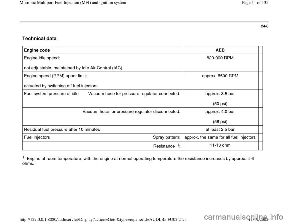
Technical data
Engine code
AEB
Engine idle speed:
not adjustable, maintained by Idle Air Control (IAC) 820-900 RPM
Engine speed (RPM) upper limit:
actuated by switching off fuel injectors approx. 6500 RPM
Fuel system pressure at idle Vacuum hose for pressure regulator connected: approx. 3.5 bar
(50 psi)
Vacuum hose for pressure regulator disconnected: approx. 4.0 bar
(58 psi)
Residual fuel pressure after 10 minutes at least 2.5 bar
Fuel injectors Spray pattern: approx. the same for all fuel injectors
Resistance
1)
:
11-13 ohm
1) Engine at room temperature; with the engine at normal operating temperature the resistance increases by approx. 4-6
ohms.
Pa
ge 11 of 135 Motronic Multi
port Fuel In
jection
(MFI
) and i
gnition s
ystem
11/19/2002 htt
p://127.0.0.1:8080/audi/servlet/Dis
play?action=Goto&t
yp
e=re
pair&id=AUDI.B5.FU02.24.1
Page 12 of 135
24-9
Fuel injection system, servicing
Servicing ignition system:
Repair Group 28
Notes:
Fuel hoses in the engine compartment must be
secured with spring-type clamps. Screw-type
clamps or equivalent must not be used.
The Engine Control Module (ECM) has On
Board Diagnostic (OBD) capability, and is
equipped with Diagnostic Trouble Code (DTC)
memory. Before repairing or adjusting any
components or systems, first check DTC
memory. Also check all vacuum connections for
leaks ("false air").
For proper operation of electrical and electronic
components, a Battery Positive Voltage (B+)
supply of at least 11.5 volts is required.
Do not use any gasket sealers or other
automotive chemical compounds that contain
silicone. Traces of silicone drawn into the
engine pass unburned into the exhaust and can
damage the oxygen sensors.
Pa
ge 12 of 135 Motronic Multi
port Fuel In
jection
(MFI
) and i
gnition s
ystem
11/19/2002 htt
p://127.0.0.1:8080/audi/servlet/Dis
play?action=Goto&t
yp
e=re
pair&id=AUDI.B5.FU02.24.1
Page 15 of 135
24-11
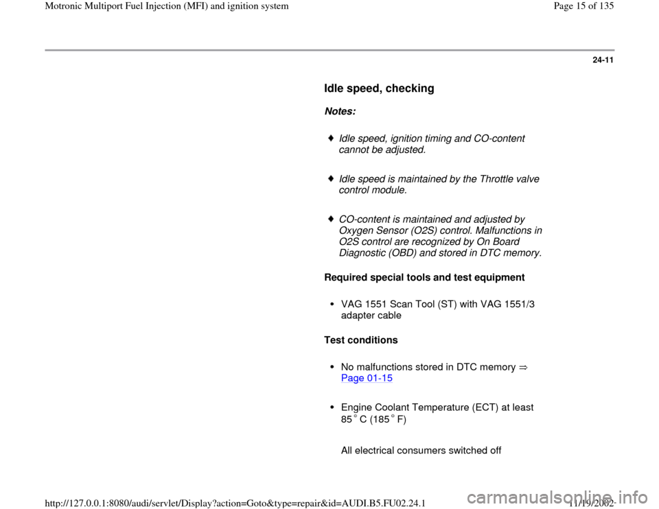
Idle speed, checking
Notes:
Idle speed, ignition timing and CO-content
cannot be adjusted.
Idle speed is maintained by the Throttle valve
control module.
CO-content is maintained and adjusted by
Oxygen Sensor (O2S) control. Malfunctions in
O2S control are recognized by On Board
Diagnostic (OBD) and stored in DTC memory.
Required special tools and test equipment
VAG 1551 Scan Tool (ST) with VAG 1551/3
adapter cable
Test conditions
No malfunctions stored in DTC memory
Page 01
-15
Engine Coolant Temperature (ECT) at least
85 C (185 F)
All electrical consumers switched off
Pa
ge 15 of 135 Motronic Multi
port Fuel In
jection
(MFI
) and i
gnition s
ystem
11/19/2002 htt
p://127.0.0.1:8080/audi/servlet/Dis
play?action=Goto&t
yp
e=re
pair&id=AUDI.B5.FU02.24.1
Page 17 of 135
24-12
Checking
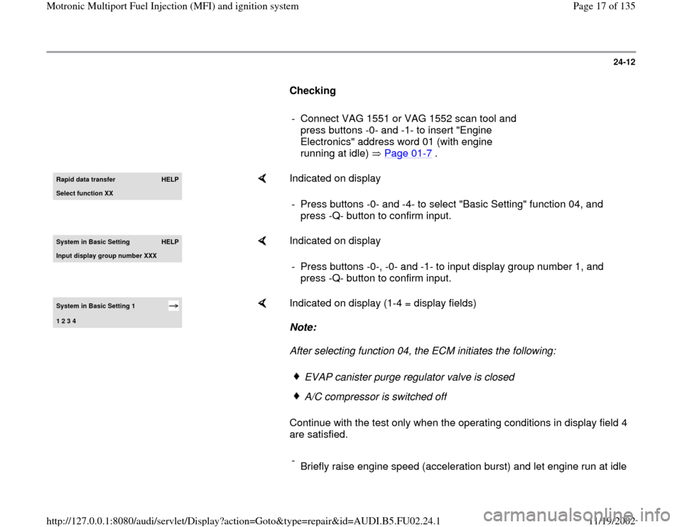
- Connect VAG 1551 or VAG 1552 scan tool and
press buttons -0- and -1- to insert "Engine
Electronics" address word 01 (with engine
running at idle) Page 01
-7 .
Rapid data transfer
HELP
Select function XX
Indicated on display
- Press buttons -0- and -4- to select "Basic Setting" function 04, and
press -Q- button to confirm input.
System in Basic Settin
g
HELP
Input displa
y group number XXX
Indicated on display
- Press buttons -0-, -0- and -1- to input display group number 1, and
press -Q- button to confirm input.
System in Basic Setting 1 1 2 3 4
Indicated on display (1-4 = display fields)
Note:
After selecting function 04, the ECM initiates the following:
Continue with the test only when the operating conditions in display field 4
are satisfied.
EVAP canister purge regulator valve is closedA/C compressor is switched of
f
-
Briefly raise engine speed (acceleration burst) and let engine run at idle
Pa
ge 17 of 135 Motronic Multi
port Fuel In
jection
(MFI
) and i
gnition s
ystem
11/19/2002 htt
p://127.0.0.1:8080/audi/servlet/Dis
play?action=Goto&t
yp
e=re
pair&id=AUDI.B5.FU02.24.1