battery AUDI A8 1999 D2 / 1.G ATQ Engine Ignition System Checking Workshop Manual
[x] Cancel search | Manufacturer: AUDI, Model Year: 1999, Model line: A8, Model: AUDI A8 1999 D2 / 1.GPages: 65, PDF Size: 0.53 MB
Page 1 of 65
28-1
Ignition system, checking
General notes on ignition system
The battery should only be disconnected and
reconnected when the ignition is turned off,
since otherwise the Engine Control Module
(ECM) can be damaged.
The Engine Control Module (ECM) is equipped
with an On Board Diagnostic (OBD)
For the electric components to work properly, a
voltage of at least 12.7 V is required.
It is possible that the control module will
recognize a malfunction and store a DTC during
some tests. After completing all tests and
repairs, DTC memory should therefore be
checked and erased if necessary.
If the engine only starts briefly and then turns
off again after troubleshooting, repair or
checking of the components, it may be that the
immobilizer is blocking the Engine Control
Module (ECM). DTC memory must then be
checked and if necessary, control module must
be adapted.
Pa
ge 1 of 65 I
gnition s
ystem, checkin
g
11/23/2002 htt
p://127.0.0.1:8080/audi/servlet/Dis
play?action=Goto&t
yp
e=re
pair&id=AUDI.B5.FU05.28.1
Page 3 of 65

The battery should only be disconnected and
reconnected when the ignition is turned off,
since otherwise the Engine Control Module
(ECM) can be damaged.
Pa
ge 3 of 65 I
gnition s
ystem, checkin
g
11/23/2002 htt
p://127.0.0.1:8080/audi/servlet/Dis
play?action=Goto&t
yp
e=re
pair&id=AUDI.B5.FU05.28.1
Page 19 of 65
28-16
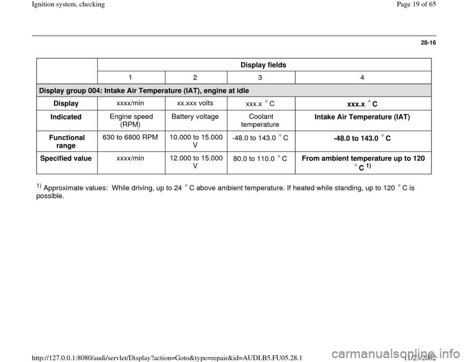
Display fields
1 2 3 4
Display group 004: Intake Air Temperature (IAT), engine at idle
Display xxxx/min xx.xxx volts
xxx.x C
xxx.x C
Indicated Engine speed
(RPM) Battery voltage Coolant
temperature Intake Air Temperature (IAT)
Functional
range 630 to 6800 RPM 10.000 to 15.000
V -48.0 to 143.0 C
-48.0 to 143.0 C
Specified value xxxx/min 12.000 to 15.000
V 80.0 to 110.0 C
From ambient temperature up to 120
C
1)
1) Approximate values: While driving, up to 24 C above ambient temperature. If heated while standing, up to 120 C is
possible.
Pa
ge 19 of 65 I
gnition s
ystem, checkin
g
11/23/2002 htt
p://127.0.0.1:8080/audi/servlet/Dis
play?action=Goto&t
yp
e=re
pair&id=AUDI.B5.FU05.28.1
Page 28 of 65
28-25
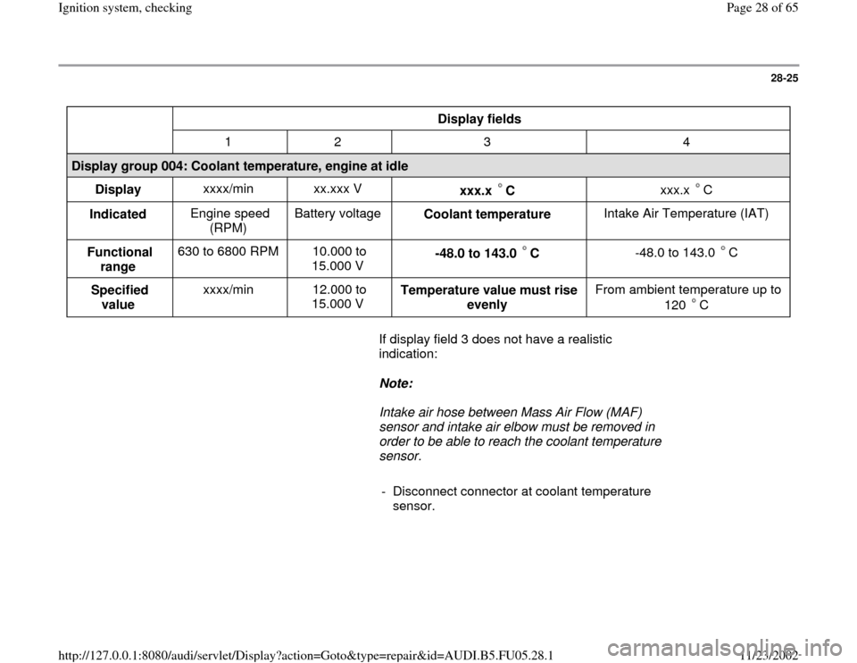
Display fields
1 2 3 4
Display group 004: Coolant temperature, engine at idle
Display xxxx/min xx.xxx V
xxx.x C
xxx.x C
Indicated Engine speed
(RPM) Battery voltage
Coolant temperature Intake Air Temperature (IAT)
Functional
range 630 to 6800 RPM 10.000 to
15.000 V -48.0 to 143.0 C
-48.0 to 143.0 C
Specified
value xxxx/min 12.000 to
15.000 V Temperature value must rise
evenly From ambient temperature up to
120 C
If display field 3 does not have a realistic
indication:
Note:
Intake air hose between Mass Air Flow (MAF)
sensor and intake air elbow must be removed in
order to be able to reach the coolant temperature
sensor.
- Disconnect connector at coolant temperature
sensor.
Pa
ge 28 of 65 I
gnition s
ystem, checkin
g
11/23/2002 htt
p://127.0.0.1:8080/audi/servlet/Dis
play?action=Goto&t
yp
e=re
pair&id=AUDI.B5.FU05.28.1
Page 34 of 65
28-31
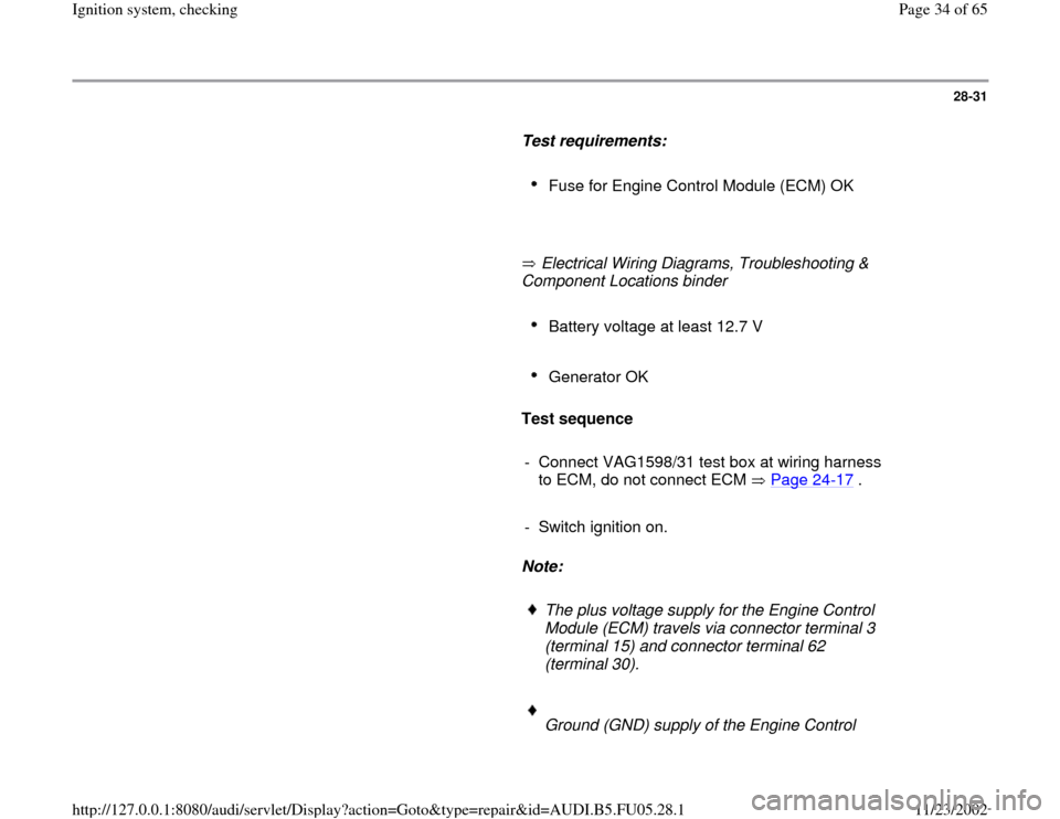
Test requirements:
Fuse for Engine Control Module (ECM) OK
Electrical Wiring Diagrams, Troubleshooting &
Component Locations binder
Battery voltage at least 12.7 V
Generator OK
Test sequence
- Connect VAG1598/31 test box at wiring harness
to ECM, do not connect ECM Page 24
-17
.
- Switch ignition on.
Note:
The plus voltage supply for the Engine Control
Module (ECM) travels via connector terminal 3
(terminal 15) and connector terminal 62
(terminal 30).
Ground (GND) supply of the Engine Control
Pa
ge 34 of 65 I
gnition s
ystem, checkin
g
11/23/2002 htt
p://127.0.0.1:8080/audi/servlet/Dis
play?action=Goto&t
yp
e=re
pair&id=AUDI.B5.FU05.28.1
Page 36 of 65
28-32
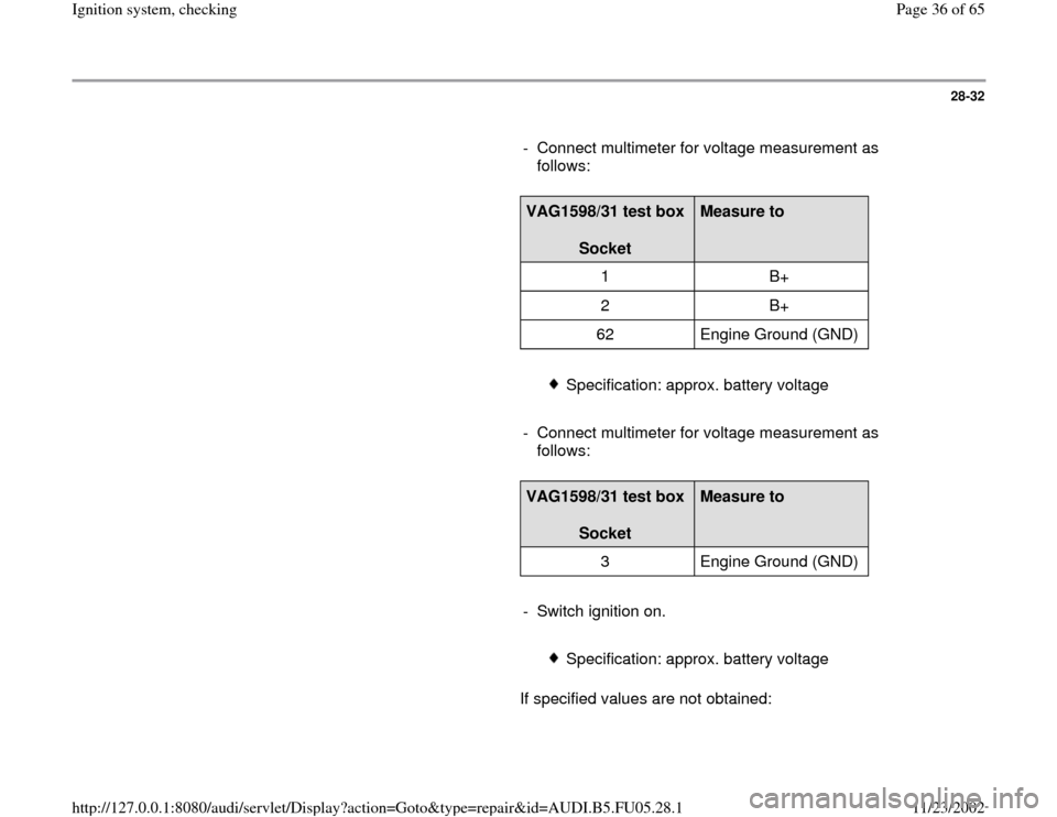
- Connect multimeter for voltage measurement as
follows:
VAG1598/31 test box
Socket
Measure to
1 B+
2 B+
62 Engine Ground (GND)
Specification: approx. battery voltage
- Connect multimeter for voltage measurement as
follows:
VAG1598/31 test box
Socket
Measure to
3 Engine Ground (GND)
- Switch ignition on.
Specification: approx. battery voltage
If specified values are not obtained:
Pa
ge 36 of 65 I
gnition s
ystem, checkin
g
11/23/2002 htt
p://127.0.0.1:8080/audi/servlet/Dis
play?action=Goto&t
yp
e=re
pair&id=AUDI.B5.FU05.28.1
Page 53 of 65
28-48
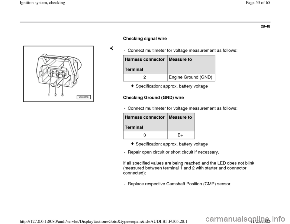
Checking signal wire
Checking Ground (GND) wire
If all specified values are being reached and the LED does not blink
(measured between terminal 1 and 2 with starter and connector
connected): - Connect multimeter for voltage measurement as follows:Harness connector
Terminal
Measure to
2 Engine Ground (GND)
Specification: approx. battery voltage
- Connect multimeter for voltage measurement as follows:
Harness connector
Terminal
Measure to
3 B+
Specification: approx. battery voltage
- Repair open circuit or short circuit if necessary.
- Replace respective Camshaft Position (CMP) sensor.
Pa
ge 53 of 65 I
gnition s
ystem, checkin
g
11/23/2002 htt
p://127.0.0.1:8080/audi/servlet/Dis
play?action=Goto&t
yp
e=re
pair&id=AUDI.B5.FU05.28.1