heating AUDI A8 1999 D2 / 1.G ATQ Engine Oxygen Sensor Control Checking
[x] Cancel search | Manufacturer: AUDI, Model Year: 1999, Model line: A8, Model: AUDI A8 1999 D2 / 1.GPages: 63, PDF Size: 0.31 MB
Page 2 of 63
24-77
If voltage change does not occur or occurs only
slowly, the following malfunctions could be
present:
Slits or holes in sensor head clogged.
Sensors suffered thermal overload.
Transition resistance in signal wire or Ground
(GND) wire.
Sensor too cold, sensor heating not
functioning.
Sensor damaged by contact spray or similar
substance (contact spray is drawn through the
fine hollow interiors by thermal fluctuations and
capillary action into the electrical wiring in
sensor).
Sensor damaged by silicon vapors (the use of
sealants containing silicon leads to trace
elements of silicon being taken in by the
engine. These silicon elements are not
combusted and damage the oxygen sensor).
Pa
ge 2 of 63 Ox
yg
en sensor control, checkin
g
11/23/2002 htt
p://127.0.0.1:8080/audi/servlet/Dis
play?action=Goto&t
yp
e=re
pair&id=AUDI.B5.FU05.24.3
Page 8 of 63
24-82
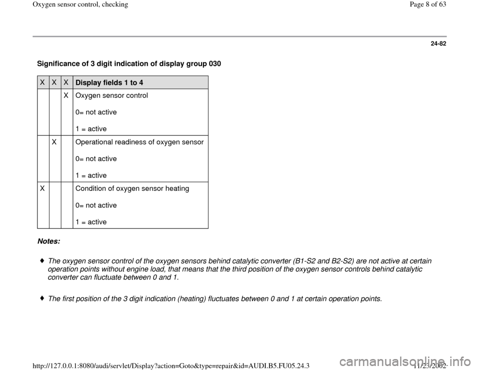
Significance of 3 digit indication of display group 030 X
X
X
Display fields 1 to 4
X Oxygen sensor control
0= not active
1 = active
X Operational readiness of oxygen sensor
0= not active
1 = active
X Condition of oxygen sensor heating
0= not active
1 = active
Notes:
The oxygen sensor control of the oxygen sensors behind catalytic converter (B1-S2 and B2-S2) are not active at certain
operation points without engine load, that means that the third position of the oxygen sensor controls behind catalytic
converter can fluctuate between 0 and 1.
The first position of the 3 digit indication (heating) fluctuates between 0 and 1 at certain operation points.
Pa
ge 8 of 63 Ox
yg
en sensor control, checkin
g
11/23/2002 htt
p://127.0.0.1:8080/audi/servlet/Dis
play?action=Goto&t
yp
e=re
pair&id=AUDI.B5.FU05.24.3
Page 11 of 63
24-85
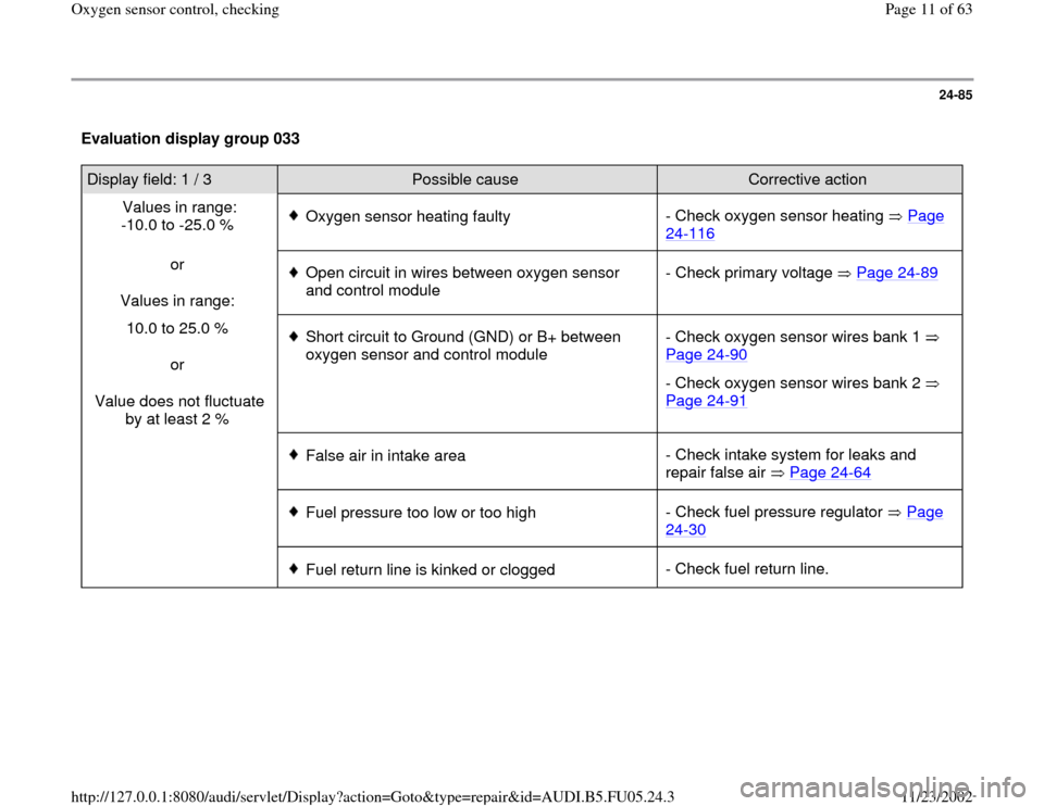
Evaluation display group 033 Display field: 1 / 3
Possible cause
Corrective action
Values in range:
-10.0 to -25.0 %
Oxygen sensor heating faulty- Check oxygen sensor heating Page
24
-116
or
Values in range:
Open circuit in wires between oxygen sensor
and control module - Check primary voltage Page 24
-89
10.0 to 25.0 %
or
Value does not fluctuate
by at least 2 %
Short circuit to Ground (GND) or B+ between
oxygen sensor and control module - Check oxygen sensor wires bank 1
Page 24
-90
- Check oxygen sensor wires bank 2
Page 24
-91
False air in intake area- Check intake system for leaks and
repair false air Page 24
-64
Fuel pressure too low or too high- Check fuel pressure regulator Page
24
-30
Fuel return line is kinked or clogged- Check fuel return line.
Pa
ge 11 of 63 Ox
yg
en sensor control, checkin
g
11/23/2002 htt
p://127.0.0.1:8080/audi/servlet/Dis
play?action=Goto&t
yp
e=re
pair&id=AUDI.B5.FU05.24.3
Page 14 of 63
24-88
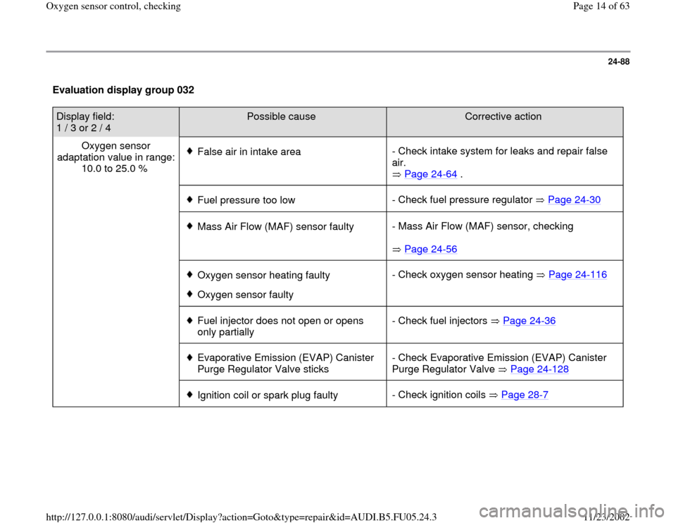
Evaluation display group 032 Display field:
1 / 3 or 2 / 4
Possible cause
Corrective action
Oxygen sensor
adaptation value in range:
10.0 to 25.0 %
False air in intake area- Check intake system for leaks and repair false
air.
Page 24
-64
.
Fuel pressure too low- Check fuel pressure regulator Page 24
-30
Mass Air Flow (MAF) sensor faulty- Mass Air Flow (MAF) sensor, checking
Page 24
-56
Oxygen sensor heating faulty
Oxygen sensor faulty- Check oxygen sensor heating Page 24
-116
Fuel injector does not open or opens
only partially - Check fuel injectors Page 24
-36
Evaporative Emission (EVAP) Canister
Purge Regulator Valve sticks - Check Evaporative Emission (EVAP) Canister
Purge Regulator Valve Page 24
-128
Ignition coil or spark plug faulty- Check ignition coils Page 28
-7
Pa
ge 14 of 63 Ox
yg
en sensor control, checkin
g
11/23/2002 htt
p://127.0.0.1:8080/audi/servlet/Dis
play?action=Goto&t
yp
e=re
pair&id=AUDI.B5.FU05.24.3
Page 30 of 63
24-101
Display fields
1 2 3 4
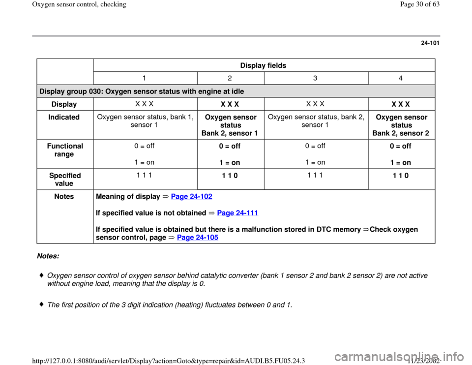
Display group 030: Oxygen sensor status with engine at idle
Display X X X
X X X X X X
X X X
Indicated Oxygen sensor status, bank 1,
sensor 1 Oxygen sensor
status
Bank 2, sensor 1 Oxygen sensor status, bank 2,
sensor 1 Oxygen sensor
status
Bank 2, sensor 2
Functional
range 0 = off
1 = on 0 = off
1 = on 0 = off
1 = on 0 = off
1 = on
Specified
value 1 1 1
1 1 0 1 1 1
1 1 0
Notes
Meaning of display Page 24
-102
If specified value is not obtained Page 24
-111
If specified value is obtained but there is a malfunction stored in DTC memory Check oxygen
sensor control, page Page 24
-105
Notes:
Oxygen sensor control of oxygen sensor behind catalytic converter (bank 1 sensor 2 and bank 2 sensor 2) are not active
without engine load, meaning that the display is 0.
The first position of the 3 digit indication (heating) fluctuates between 0 and 1.
Pa
ge 30 of 63 Ox
yg
en sensor control, checkin
g
11/23/2002 htt
p://127.0.0.1:8080/audi/servlet/Dis
play?action=Goto&t
yp
e=re
pair&id=AUDI.B5.FU05.24.3
Page 32 of 63
24-102
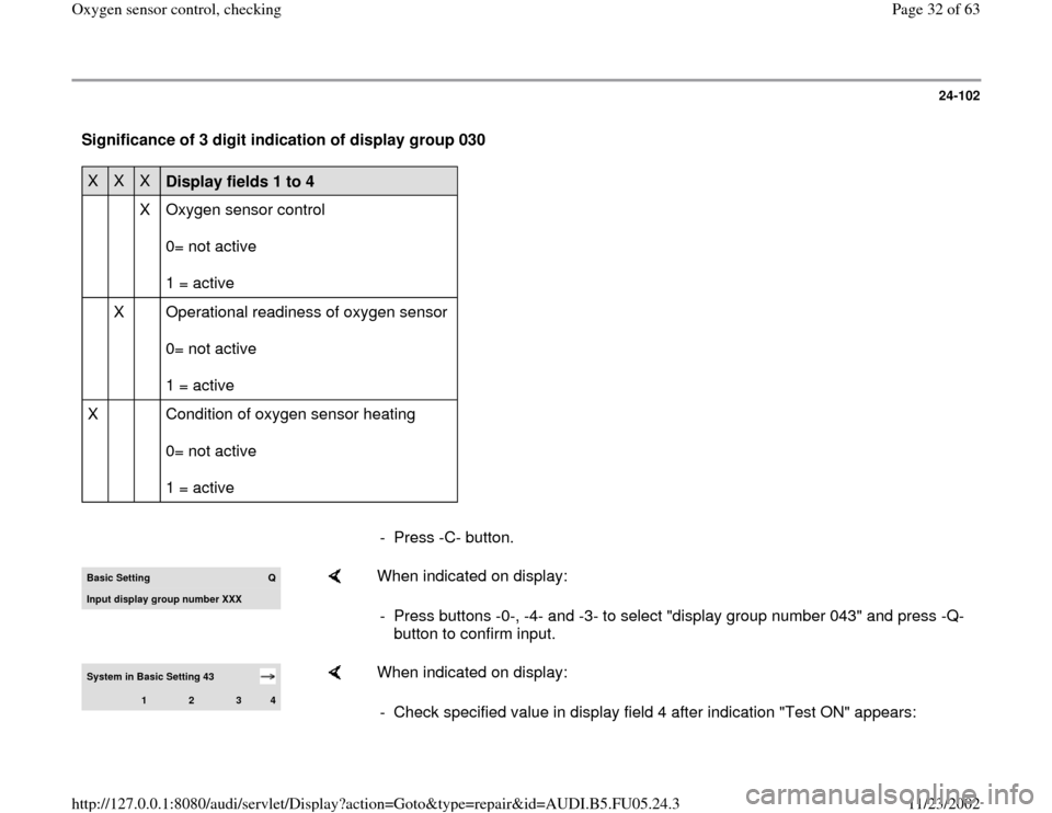
Significance of 3 digit indication of display group 030 X
X
X
Display fields 1 to 4
X Oxygen sensor control
0= not active
1 = active
X Operational readiness of oxygen sensor
0= not active
1 = active
X Condition of oxygen sensor heating
0= not active
1 = active
- Press -C- button.Basic Setting
Q
Input displa
y group number XXX
When indicated on display:
- Press buttons -0-, -4- and -3- to select "display group number 043" and press -Q-
button to confirm input.
System in Basic Setting 43
1
2
3
4
When indicated on display:
- Check specified value in display field 4 after indication "Test ON" appears:
Pa
ge 32 of 63 Ox
yg
en sensor control, checkin
g
11/23/2002 htt
p://127.0.0.1:8080/audi/servlet/Dis
play?action=Goto&t
yp
e=re
pair&id=AUDI.B5.FU05.24.3
Page 49 of 63
24-116
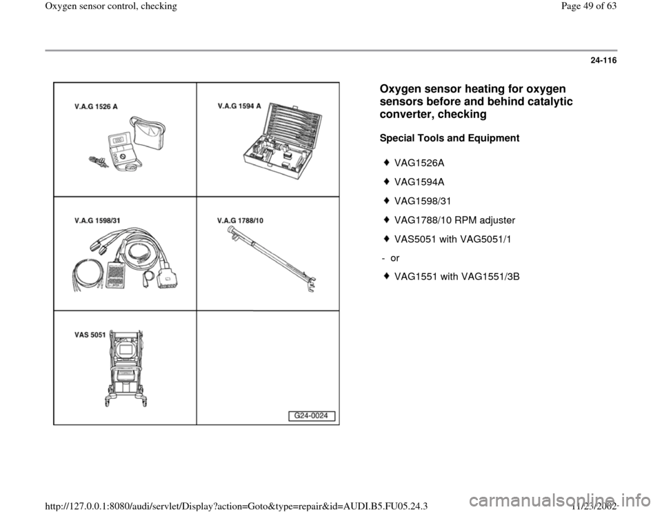
Oxygen sensor heating for oxygen
sensors before and behind catalytic
converter, checking
Special Tools and Equipment
VAG1526A
VAG1594A
VAG1598/31
VAG1788/10 RPM adjuster
VAS5051 with VAG5051/1
- or
VAG1551 with VAG1551/3B
Pa
ge 49 of 63 Ox
yg
en sensor control, checkin
g
11/23/2002 htt
p://127.0.0.1:8080/audi/servlet/Dis
play?action=Goto&t
yp
e=re
pair&id=AUDI.B5.FU05.24.3
Page 50 of 63
24-117
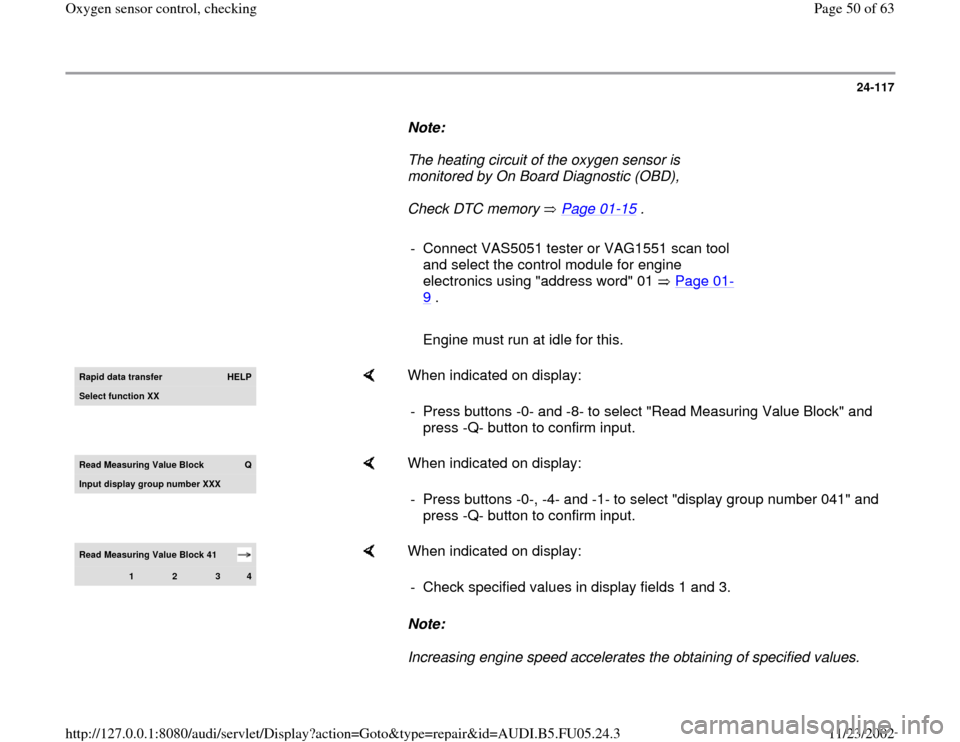
Note:
The heating circuit of the oxygen sensor is
monitored by On Board Diagnostic (OBD),
Check DTC memory Page 01
-15
.
- Connect VAS5051 tester or VAG1551 scan tool
and select the control module for engine
electronics using "address word" 01 Page 01
-
9 .
Engine must run at idle for this.Rapid data transfer
HELP
Select function XX
When indicated on display:
- Press buttons -0- and -8- to select "Read Measuring Value Block" and
press -Q- button to confirm input.
Read Measurin
g Value Block
Q
Input displa
y group number XXX
When indicated on display:
- Press buttons -0-, -4- and -1- to select "display group number 041" and
press -Q- button to confirm input.
Read Measuring Value Block 41
1
2
3
4
When indicated on display:
Note:
Increasing engine speed accelerates the obtaining of specified values. - Check specified values in display fields 1 and 3.
Pa
ge 50 of 63 Ox
yg
en sensor control, checkin
g
11/23/2002 htt
p://127.0.0.1:8080/audi/servlet/Dis
play?action=Goto&t
yp
e=re
pair&id=AUDI.B5.FU05.24.3
Page 51 of 63
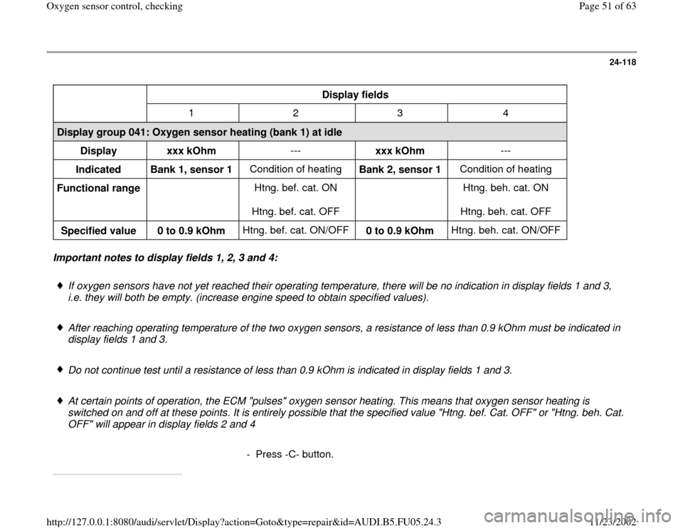
24-118
Display fields
1 2 3 4
Display group 041: Oxygen sensor heating (bank 1) at idle
Display
xxx kOhm ---
xxx kOhm ---
Indicated
Bank 1, sensor 1 Condition of heating
Bank 2, sensor 1 Condition of heating
Functional range Htng. bef. cat. ON
Htng. bef. cat. OFF Htng. beh. cat. ON
Htng. beh. cat. OFF
Specified value
0 to 0.9 kOhm Htng. bef. cat. ON/OFF
0 to 0.9 kOhm Htng. beh. cat. ON/OFF Important notes to display fields 1, 2, 3 and 4:
If oxygen sensors have not yet reached their operating temperature, there will be no indication in display fields 1 and 3,
i.e. they will both be empty. (increase engine speed to obtain specified values).
After reaching operating temperature of the two oxygen sensors, a resistance of less than 0.9 kOhm must be indicated in
display fields 1 and 3.
Do not continue test until a resistance of less than 0.9 kOhm is indicated in display fields 1 and 3.
At certain points of operation, the ECM "pulses" oxygen sensor heating. This means that oxygen sensor heating is
switched on and off at these points. It is entirely possible that the specified value "Htng. bef. Cat. OFF" or "Htng. beh. Cat.
OFF" will appear in display fields 2 and 4
- Press -C- button.
Pa
ge 51 of 63 Ox
yg
en sensor control, checkin
g
11/23/2002 htt
p://127.0.0.1:8080/audi/servlet/Dis
play?action=Goto&t
yp
e=re
pair&id=AUDI.B5.FU05.24.3
Page 53 of 63
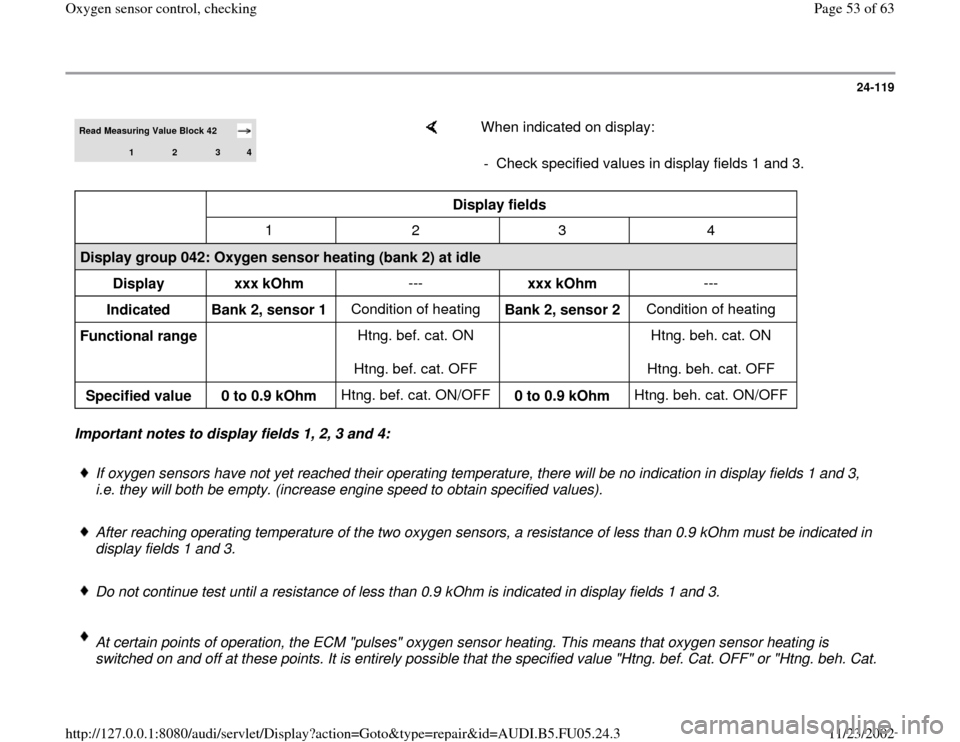
24-119
Read Measuring Value Block 42
1
2
3
4
When indicated on display:
- Check specified values in display fields 1 and 3.
Display fields
1 2 3 4
Display group 042: Oxygen sensor heating (bank 2) at idle
Display
xxx kOhm ---
xxx kOhm ---
Indicated
Bank 2, sensor 1 Condition of heating
Bank 2, sensor 2 Condition of heating
Functional range Htng. bef. cat. ON
Htng. bef. cat. OFF Htng. beh. cat. ON
Htng. beh. cat. OFF
Specified value
0 to 0.9 kOhm Htng. bef. cat. ON/OFF
0 to 0.9 kOhm Htng. beh. cat. ON/OFF Important notes to display fields 1, 2, 3 and 4:
If oxygen sensors have not yet reached their operating temperature, there will be no indication in display fields 1 and 3,
i.e. they will both be empty. (increase engine speed to obtain specified values).
After reaching operating temperature of the two oxygen sensors, a resistance of less than 0.9 kOhm must be indicated in
display fields 1 and 3.
Do not continue test until a resistance of less than 0.9 kOhm is indicated in display fields 1 and 3.
At certain points of operation, the ECM "pulses" oxygen sensor heating. This means that oxygen sensor heating is
switched on and off at these points. It is entirely possible that the specified value "Htng. bef. Cat. OFF" or "Htng. beh. Cat.
Pa
ge 53 of 63 Ox
yg
en sensor control, checkin
g
11/23/2002 htt
p://127.0.0.1:8080/audi/servlet/Dis
play?action=Goto&t
yp
e=re
pair&id=AUDI.B5.FU05.24.3