transmission AUDI A8 2000 D2 / 1.G 01V Transmission Electrical Testing Owner's Guide
[x] Cancel search | Manufacturer: AUDI, Model Year: 2000, Model line: A8, Model: AUDI A8 2000 D2 / 1.GPages: 66, PDF Size: 0.28 MB
Page 48 of 66
01-302
Wiring between transmission and 88-pin
connector for Transmission Control
Module (TCM) -J217-, testing
Perform if:
Output Diagnostic Test Mode (DTM) or
Electrical test indicates malfunctions in the
transmission, the TCM -J217-, or in the
corresponding wiring.
Test conditions
Ignition switched off
Connect VAG1598/20 adapter only to 88-pin
connector of transmission wiring harness.
Perform measurements with VAG1598/20
adapter on the outside of the vehicle
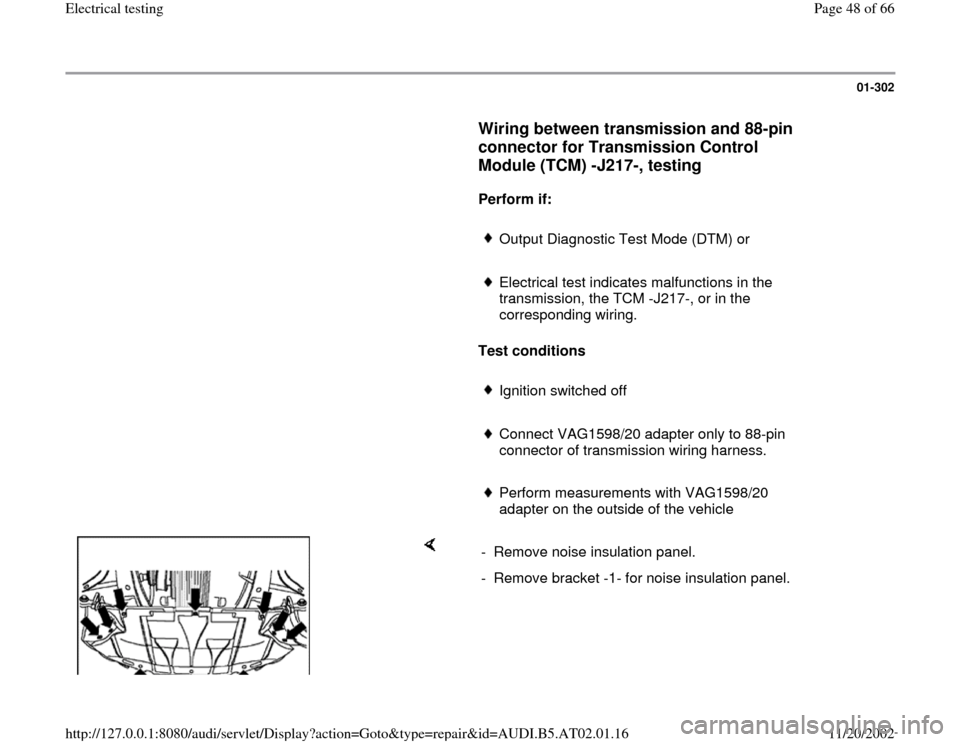
- Remove noise insulation panel.
- Remove bracket -1- for noise insulation panel.
Pa
ge 48 of 66 Electrical testin
g
11/20/2002 htt
p://127.0.0.1:8080/audi/servlet/Dis
play?action=Goto&t
yp
e=re
pair&id=AUDI.B5.AT02.01.16
Page 49 of 66
01-303
Wiring to 16-pin connector on transmission,
testing
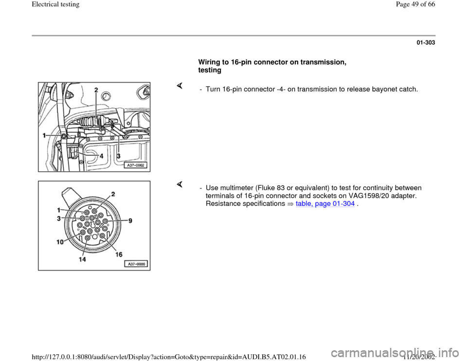
- Turn 16-pin connector -4- on transmission to release bayonet catch.
- Use multimeter (Fluke 83 or equivalent) to test for continuity between
terminals of 16-pin connector and sockets on VAG1598/20 adapter.
Resistance specifications table, page 01
-304
.
Pa
ge 49 of 66 Electrical testin
g
11/20/2002 htt
p://127.0.0.1:8080/audi/servlet/Dis
play?action=Goto&t
yp
e=re
pair&id=AUDI.B5.AT02.01.16
Page 52 of 66
01-305
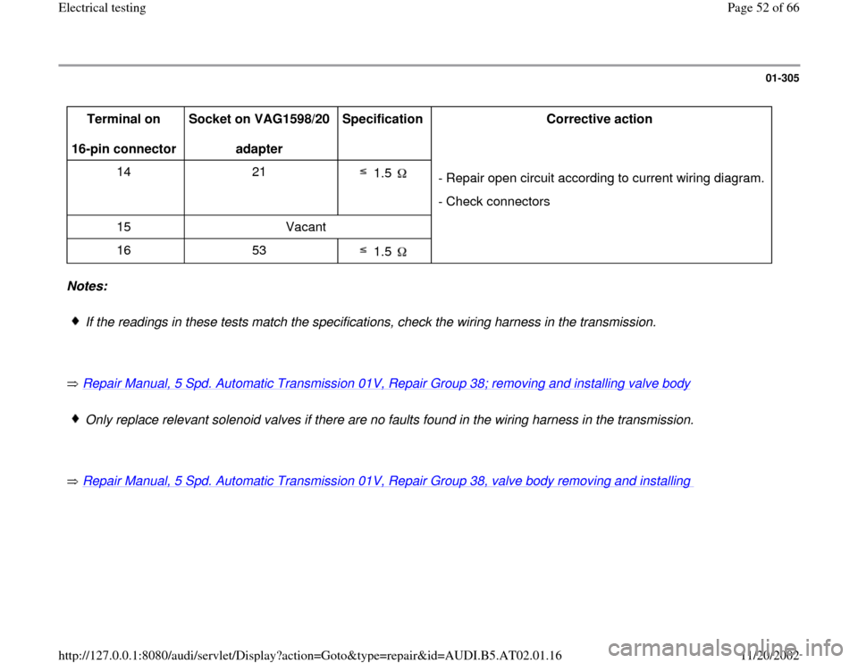
Terminal on
16-pin connector Socket on VAG1598/20
adapter Specification
Corrective action
14 21
1.5
- Repair open circuit according to current wiring diagram.
- Check connectors
15 Vacant
16 53
1.5
Notes:
If the readings in these tests match the specifications, check the wiring harness in the transmission.
Repair Manual, 5 Spd. Automatic Transmission 01V, Repair Group 38; removing and installing valve body
Only replace relevant solenoid valves if there are no faults found in the wiring harness in the transmission.
Repair Manual, 5 Spd. Automatic Transmission 01V, Repair Group 38, valve body removing and installing
Pa
ge 52 of 66 Electrical testin
g
11/20/2002 htt
p://127.0.0.1:8080/audi/servlet/Dis
play?action=Goto&t
yp
e=re
pair&id=AUDI.B5.AT02.01.16
Page 53 of 66
01-306
Multi-function Transmission Range (TR)
switch, checking
Note:
Check the measuring value block for the TR-
switch display group number 004 page 01
-
203
before checking the TR-switch.
Be sure that selector lever cable is properly
adjusted.
Two different multi-function switches were
used in production:
1. Multi-function switch with 8 - pin connector
checking starting page 01
-308
.
2. Multi-function switch with 10 - pin connector
checking starting page 01
-319
.
Pa
ge 53 of 66 Electrical testin
g
11/20/2002 htt
p://127.0.0.1:8080/audi/servlet/Dis
play?action=Goto&t
yp
e=re
pair&id=AUDI.B5.AT02.01.16
Page 54 of 66
01-307
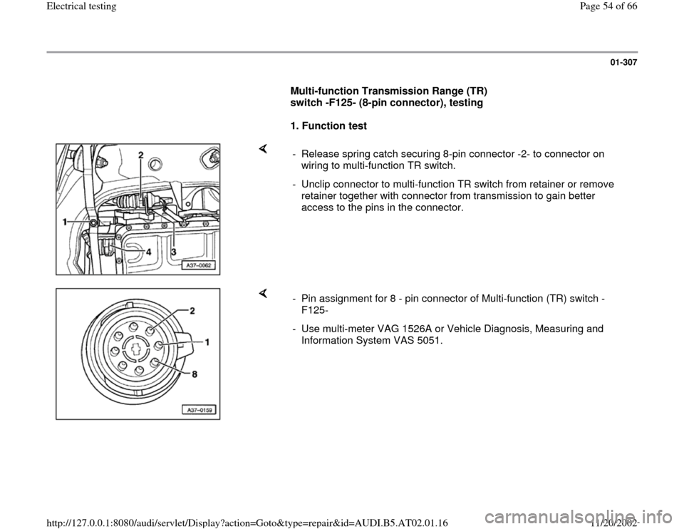
Multi-function Transmission Range (TR)
switch -F125- (8-pin connector), testing
1. Function test
- Release spring catch securing 8-pin connector -2- to connector on
wiring to multi-function TR switch.
- Unclip connector to multi-function TR switch from retainer or remove
retainer together with connector from transmission to gain better
access to the pins in the connector.
- Pin assignment for 8 - pin connector of Multi-function (TR) switch -
F125-
- Use multi-meter VAG 1526A or Vehicle Diagnosis, Measuring and
Information System VAS 5051.
Pa
ge 54 of 66 Electrical testin
g
11/20/2002 htt
p://127.0.0.1:8080/audi/servlet/Dis
play?action=Goto&t
yp
e=re
pair&id=AUDI.B5.AT02.01.16
Page 55 of 66
01-308
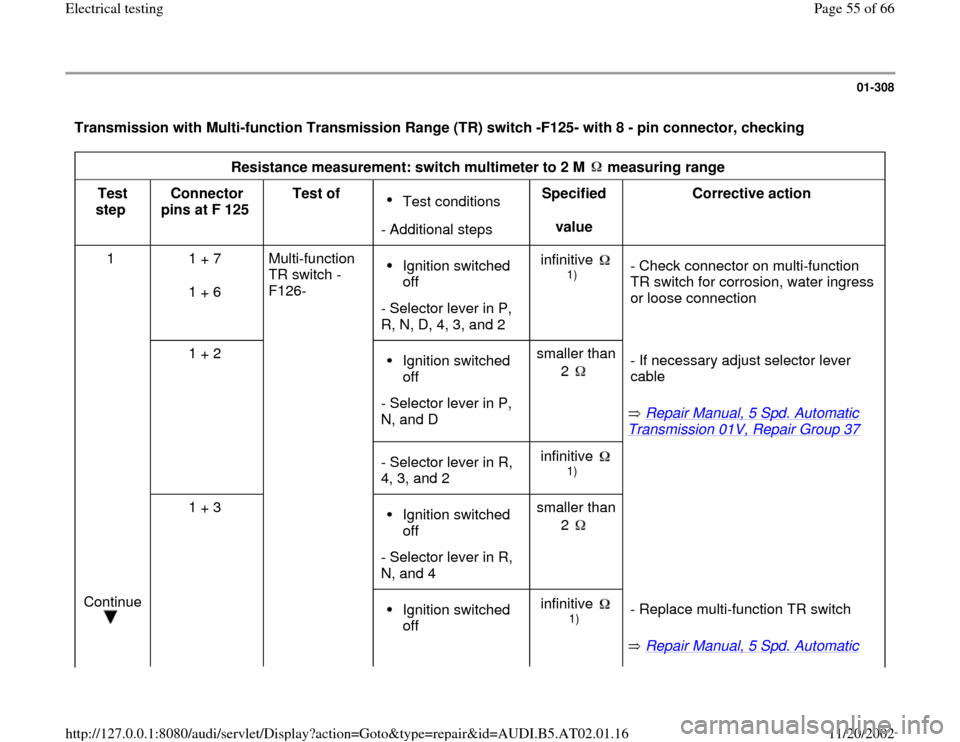
Transmission with Multi-function Transmission Range (TR) switch -F125- with 8 - pin connector, checking
Resistance measurement: switch multimeter to 2 M measuring range
Test
step Connector
pins at F 125 Test of
Test conditions
- Additional stepsSpecified
value Corrective action
1 1 + 7
1 + 6 Multi-function
TR switch -
F126- Ignition switched
off
- Selector lever in P,
R, N, D, 4, 3, and 2 infinitive
1)
- Check connector on multi-function
TR switch for corrosion, water ingress
or loose connection
1 + 2
Ignition switched
off
- Selector lever in P,
N, and D smaller than
2
Repair Manual, 5 Spd. Automatic
Transmission 01V, Repair Group 37
- If necessary adjust selector lever
cable
- Selector lever in R,
4, 3, and 2 infinitive
1)
1 + 3
Ignition switched
off
- Selector lever in R,
N, and 4 smaller than
2
Continue
Ignition switched
off infinitive
1)
Repair Manual, 5 Spd. Automatic - Replace multi-function TR switch
Pa
ge 55 of 66 Electrical testin
g
11/20/2002 htt
p://127.0.0.1:8080/audi/servlet/Dis
play?action=Goto&t
yp
e=re
pair&id=AUDI.B5.AT02.01.16
Page 56 of 66
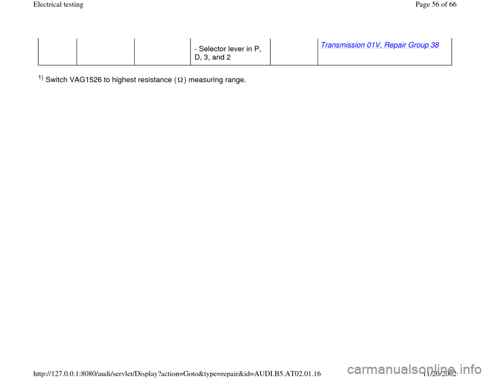
- Selector lever in P,
D, 3, and 2 Transmission 01V, Repair Group 38
1) Switch VAG1526 to highest resistance ( ) measuring range.
Pa
ge 56 of 66 Electrical testin
g
11/20/2002 htt
p://127.0.0.1:8080/audi/servlet/Dis
play?action=Goto&t
yp
e=re
pair&id=AUDI.B5.AT02.01.16
Page 57 of 66
01-309
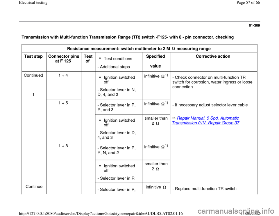
Transmission with Multi-function Transmission Range (TR) switch -F125- with 8 - pin connector, checking
Resistance measurement: switch multimeter to 2 M measuring range
Test step
Connector pins
at F 125 Test
of
Test conditions
- Additional stepsSpecified
value Corrective action
Continued
1 1 + 4 Ignition switched
off
- Selector lever in N,
D, 4, and 2 infinitive
1)
- Check connector on multi-function TR
switch for corrosion, water ingress or loose
connection
1 + 5
- Selector lever in P,
R, and 3 infinitive
1)
- If necessary adjust selector lever cable
Ignition switched
off
- Selector lever in D,
4, and 3 smaller than
2
Repair Manual, 5 Spd. Automatic
Transmission 01V, Repair Group 37
1 + 8
- Selector lever in P,
R, N, and 2 infinitive
1)
Ignition switched
off
- Selector lever in Rsmaller than
2
Continue
- Selector lever in P, infinitive
- Replace multi-function TR switch
Pa
ge 57 of 66 Electrical testin
g
11/20/2002 htt
p://127.0.0.1:8080/audi/servlet/Dis
play?action=Goto&t
yp
e=re
pair&id=AUDI.B5.AT02.01.16
Page 58 of 66
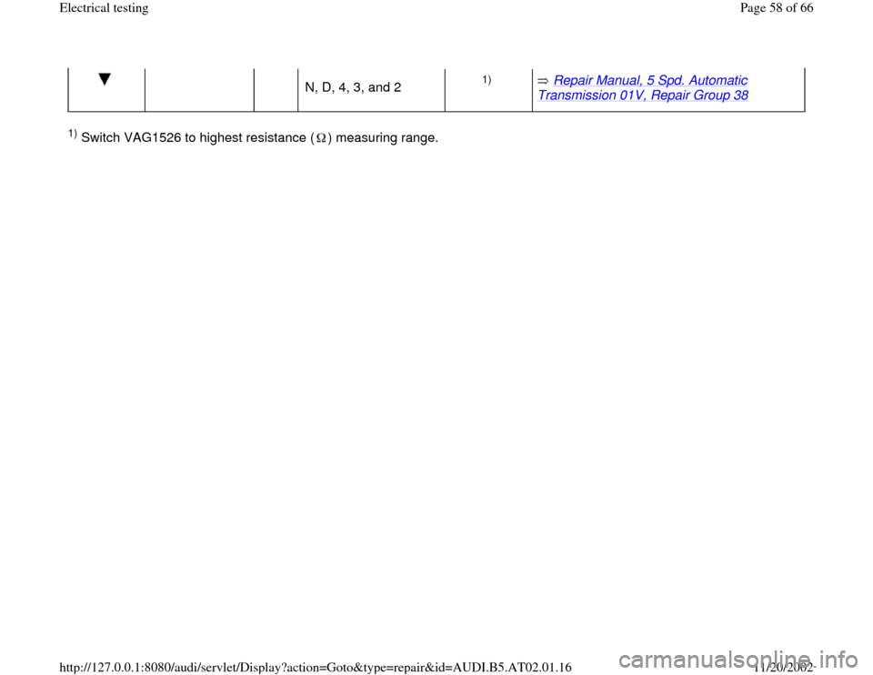
N, D, 4, 3, and 2
1)
Repair Manual, 5 Spd. Automatic
Transmission 01V, Repair Group 38
1) Switch VAG1526 to highest resistance ( ) measuring range.
Pa
ge 58 of 66 Electrical testin
g
11/20/2002 htt
p://127.0.0.1:8080/audi/servlet/Dis
play?action=Goto&t
yp
e=re
pair&id=AUDI.B5.AT02.01.16
Page 59 of 66
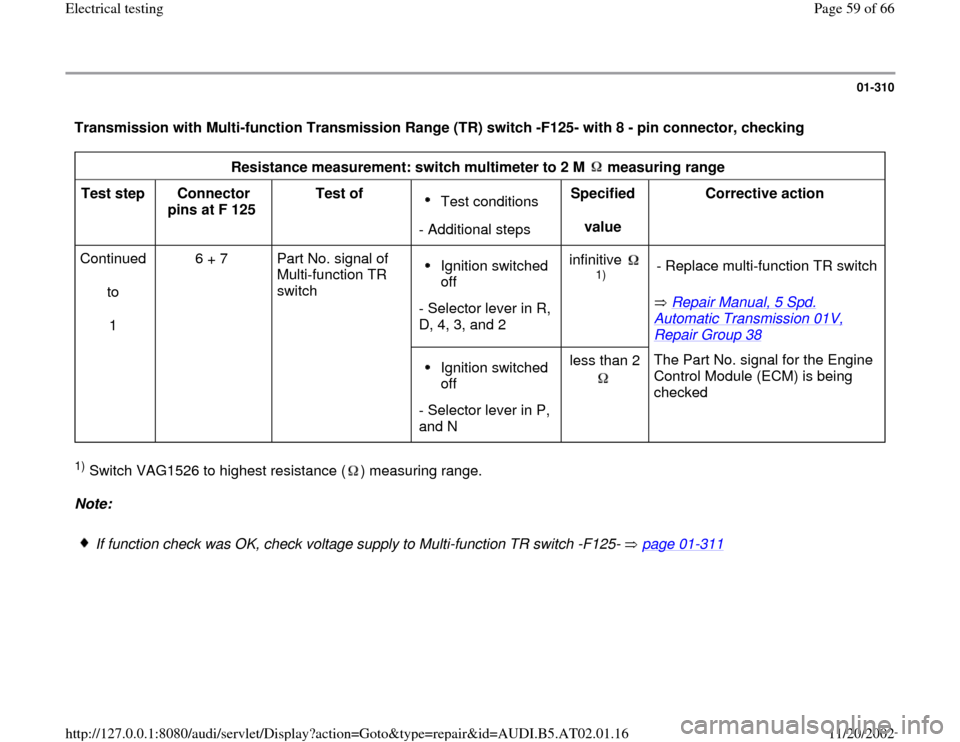
01-310
Transmission with Multi-function Transmission Range (TR) switch -F125- with 8 - pin connector, checking
Resistance measurement: switch multimeter to 2 M measuring range
Test step
Connector
pins at F 125 Test of
Test conditions
- Additional stepsSpecified
value Corrective action
Continued
to
1 6 + 7 Part No. signal of
Multi-function TR
switch Ignition switched
off
- Selector lever in R,
D, 4, 3, and 2 infinitive
1)
Repair Manual, 5 Spd.
Automatic Transmission 01V, Repair Group 38
- Replace multi-function TR switch
Ignition switched
off
- Selector lever in P,
and N less than 2
The Part No. signal for the Engine
Control Module (ECM) is being
checked
1) Switch VAG1526 to highest resistance ( ) measuring range. Note:
If function check was OK, check voltage supply to Multi-function TR switch -F125- page 01
-311
Pa
ge 59 of 66 Electrical testin
g
11/20/2002 htt
p://127.0.0.1:8080/audi/servlet/Dis
play?action=Goto&t
yp
e=re
pair&id=AUDI.B5.AT02.01.16